Package Sensors contains ideal measurement components to determine absolute and relative kinematic quantities, as well as cut-forces, cut-torques and power. All measured quantities can be provided in every desired coordinate system.
Extends from Modelica.Icons.SensorsPackage (Icon for packages containing sensors).
| Name | Description |
|---|---|
| Measure absolute kinematic quantities of frame connector | |
| Measure relative kinematic quantities between two frame connectors | |
| Measure absolute position vector of the origin of a frame connector | |
| Measure absolute velocity vector of origin of frame connector | |
| Measure absolute angles between frame connector and the world frame | |
| Measure absolute angular velocity of frame connector | |
| Measure relative position vector between the origins of two frame connectors | |
| Measure relative velocity vector between the origins of two frame connectors | |
| Measure relative angles between two frame connectors | |
| Measure relative angular velocity between two frame connectors | |
| Measure the distance between the origins of two frame connectors | |
| Measure cut force vector | |
| Measure cut torque vector | |
| Measure cut force and cut torque vector | |
| Measure power flowing from frame_a to frame_b | |
| Transform absolute vector in to another frame | |
| Transform relative vector in to another frame | |
| Internal package, should not be used by user |
 Modelica.Mechanics.MultiBody.Sensors.AbsoluteSensor
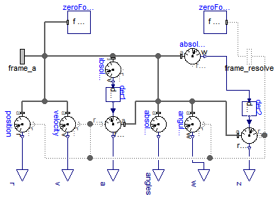
Absolute kinematic quantities of frame_a are determined and provided at the conditional output signal connectors. For example, if parameter "get_r = true", the connector "r" is enabled and contains the absolute vector from the world frame to the origin of frame_a. The following quantities can be provided as output signals:
Via parameter resolveInFrame it is defined, in which frame a vector is resolved:
| resolveInFrame = Types.ResolveInFrameA. | Meaning |
|---|---|
| world | Resolve vectors in world frame |
| frame_a | Resolve vectors in frame_a |
| frame_resolve | Resolve vectors in frame_resolve |
If resolveInFrame = Types.ResolveInFrameA.frame_resolve, the conditional connector "frame_resolve" is enabled and the vectors are resolved in the frame, to which frame_resolve is connected. Note, if this connector is enabled, it must be connected.
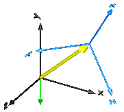
In the following figure the animation of an AbsoluteSensor component is shown. The light blue coordinate system is frame_a and the yellow arrow is the animated sensor.
Velocity, acceleration, angular velocity and angular acceleration are determined by differentiating them in the world frame and then transforming them in to the frame defined by resolveInFrame.
For example, if resolveInFrame = Types.ResolveInFrameA.frame_a, then
   v0 = der(frame_a.r0);
   v  = resolve2(frame_a.R, v0);
is returned, i.e., the derivative of the absolute distance from the world frame to the origin of frame_a, resolved in frame_a.
The cut-force and the cut-torque in frame_resolve are always zero, whether frame_resolve is connected or not.
If get_angles = true, the 3 angles to rotate the world frame into frame_a along the axes defined by parameter sequence are returned. For example, if sequence = {3,1,2} then the world frame is rotated around angles[1] along the z-axis, afterwards it is rotated around angles[2] along the x-axis, and finally it is rotated around angles[3] along the y-axis and is then identical to frame_a. The 3 angles are returned in the range
-p <= angles[i] <= p
There are two solutions for "angles[1]" in this range. Via parameter guessAngle1 (default = 0) the returned solution is selected such that |angles[1] - guessAngle1| is minimal. The absolute transformation matrix of frame_a may be in a singular configuration with respect to "sequence", i.e., there is an infinite number of angle values leading to the same absolute transformation matrix. In this case, the returned solution is selected by setting angles[1] = guessAngle1. Then angles[2] and angles[3] can be uniquely determined in the above range.
The parameter sequence has the restriction that only values 1,2,3 can be used and that sequence[1] ≠ sequence[2] and sequence[2] ≠ sequence[3]. Often used values are:
  sequence = {1,2,3}  // Cardan or Tait-Bryan angle sequence
           = {3,1,3}  // Euler angle sequence
           = {3,2,1}
Extends from Modelica.Mechanics.MultiBody.Sensors.Internal.PartialAbsoluteSensor (Partial absolute sensor model for sensors defined by components).
| Type | Name | Default | Description |
|---|---|---|---|
| Boolean | animation | true | = true, if animation shall be enabled (show arrow) |
| ResolveInFrameA | resolveInFrame | Modelica.Mechanics.MultiBody... | Frame in which vectors are resolved (1: world, 2: frame_a, 3: frame_resolve) |
| Boolean | get_r | false | = true, to measure the absolute position vector of the origin of frame_a |
| Boolean | get_v | false | = true, to measure the absolute velocity of the origin of frame_a |
| Boolean | get_a | false | = true, to measure the absolute acceleration of the origin of frame_a |
| Boolean | get_w | false | = true, to measure the absolute angular velocity of frame_a |
| Boolean | get_z | false | = true, to measure the absolute angular acceleration of frame_a |
| 3 angles to rotate the world frame into frame_a along the axes defined in "sequence" | |||
| Boolean | get_angles | false | = true, to measure the 3 rotation angles |
| RotationSequence | sequence | {1,2,3} | If get_angles=true: Angles are returned to rotate world frame around axes sequence[1], sequence[2] and finally sequence[3] into frame_a |
| Angle | guessAngle1 | 0 | If get_angles=true: Select angles[1] such that abs(angles[1] - guessAngle1) is a minimum [rad] |
| Animation | |||
| if animation = true | |||
| Diameter | arrowDiameter | world.defaultArrowDiameter | Diameter of absolute arrow from world frame to frame_a [m] |
| Color | arrowColor | Modelica.Mechanics.MultiBody... | Color of absolute arrow from world frame to frame_b |
| SpecularCoefficient | specularCoefficient | world.defaultSpecularCoeffic... | Reflection of ambient light (= 0: light is completely absorbed) |
| Type | Name | Description |
|---|---|---|
| output RealOutput | r[3] | Absolute position vector frame_a.r_0 resolved in frame defined by resolveInFrame [m] |
| output RealOutput | v[3] | Absolute velocity vector [m/s] |
| output RealOutput | a[3] | Absolute acceleration vector [m/s2] |
| output RealOutput | angles[3] | Angles to rotate world frame into frame_a via 'sequence' [rad] |
| output RealOutput | w[3] | Absolute angular velocity vector [1/s] |
| output RealOutput | z[3] | Absolute angular acceleration vector [1/s2] |
| Frame_a | frame_a | Coordinate system at which the kinematic quantities are measured |
| Frame_resolve | frame_resolve | If resolveInFrame = Types.ResolveInFrameA.frame_resolve, the output signals are resolved in this frame |
model AbsoluteSensor "Measure absolute kinematic quantities of frame connector" import SI = Modelica.SIunits;Blocks.Interfaces.RealOutput r[3](each final quantity="Position", each final unit = "m") if get_r "Absolute position vector frame_a.r_0 resolved in frame defined by resolveInFrame"; Blocks.Interfaces.RealOutput v[3](each final quantity="Velocity", each final unit = "m/s") if get_v "Absolute velocity vector"; Blocks.Interfaces.RealOutput a[3](each final quantity="Acceleration", each final unit = "m/s2") if get_a "Absolute acceleration vector"; Blocks.Interfaces.RealOutput angles[3](each final quantity="Angles", each final unit = "rad", each displayUnit = "deg") if get_angles "Angles to rotate world frame into frame_a via 'sequence'"; Blocks.Interfaces.RealOutput w[3](each final quantity="AngularVelocity", each final unit = "1/s") if get_w "Absolute angular velocity vector"; Blocks.Interfaces.RealOutput z[3](each final quantity="AngularAcceleration", each final unit = "1/s2") if get_z "Absolute angular acceleration vector"; extends Modelica.Mechanics.MultiBody.Sensors.Internal.PartialAbsoluteSensor;Interfaces.Frame_resolve frame_resolve if resolveInFrame == Modelica.Mechanics.MultiBody.Types.ResolveInFrameA.frame_resolve "If resolveInFrame = Types.ResolveInFrameA.frame_resolve, the output signals are resolved in this frame"; parameter Boolean animation=true "= true, if animation shall be enabled (show arrow)"; parameter Modelica.Mechanics.MultiBody.Types.ResolveInFrameA resolveInFrame= Modelica.Mechanics.MultiBody.Types.ResolveInFrameA.frame_a "Frame in which vectors are resolved (1: world, 2: frame_a, 3: frame_resolve)"; parameter Boolean get_r=false "= true, to measure the absolute position vector of the origin of frame_a"; parameter Boolean get_v=false "= true, to measure the absolute velocity of the origin of frame_a"; parameter Boolean get_a=false "= true, to measure the absolute acceleration of the origin of frame_a"; parameter Boolean get_w=false "= true, to measure the absolute angular velocity of frame_a"; parameter Boolean get_z=false "= true, to measure the absolute angular acceleration of frame_a"; parameter Boolean get_angles=false "= true, to measure the 3 rotation angles"; parameter Types.RotationSequence sequence( min={1,1,1}, max={3,3,3}) = {1,2,3} "If get_angles=true: Angles are returned to rotate world frame around axes sequence[1], sequence[2] and finally sequence[3] into frame_a"; parameter SI.Angle guessAngle1=0 "If get_angles=true: Select angles[1] such that abs(angles[1] - guessAngle1) is a minimum"; input SI.Diameter arrowDiameter=world.defaultArrowDiameter "Diameter of absolute arrow from world frame to frame_a"; input Types.Color arrowColor=Modelica.Mechanics.MultiBody.Types.Defaults.SensorColor "Color of absolute arrow from world frame to frame_b"; input Types.SpecularCoefficient specularCoefficient = world.defaultSpecularCoefficient "Reflection of ambient light (= 0: light is completely absorbed)";protected AbsolutePosition position(resolveInFrame=resolveInFrame) if get_r; protected AbsoluteVelocity velocity(resolveInFrame=resolveInFrame) if get_v; Modelica.Mechanics.MultiBody.Sensors.AbsoluteAngles absoluteAngles(sequence= sequence, guessAngle1=guessAngle1) if get_angles; AbsoluteAngularVelocity angularVelocity(resolveInFrame=resolveInFrame) if get_w; protected Blocks.Continuous.Der der1[3] if get_a; protected Blocks.Continuous.Der der2[3] if get_z; protected Modelica.Mechanics.MultiBody.Sensors.TansformAbsoluteVector transformVector_a( frame_r_in=Modelica.Mechanics.MultiBody.Types.ResolveInFrameA.world, frame_r_out=resolveInFrame) if get_a; Modelica.Mechanics.MultiBody.Sensors.TansformAbsoluteVector transformVector_z( frame_r_in=Modelica.Mechanics.MultiBody.Types.ResolveInFrameA.world, frame_r_out=resolveInFrame) if get_z; protected outer Modelica.Mechanics.MultiBody.World world; Modelica.Mechanics.MultiBody.Visualizers.Advanced.Arrow arrow( r_head=frame_a.r_0, diameter=arrowDiameter, color=arrowColor, specularCoefficient) if world.enableAnimation and animation;protected AbsoluteVelocity absoluteVelocity(resolveInFrame=Modelica.Mechanics.MultiBody.Types.ResolveInFrameA.world) if get_a; AbsoluteAngularVelocity absoluteAngularVelocity(resolveInFrame=Modelica.Mechanics.MultiBody.Types.ResolveInFrameA.world) if get_z; Internal.ZeroForceAndTorque zeroForce1; Internal.ZeroForceAndTorque zeroForce2 if resolveInFrame == Modelica.Mechanics.MultiBody.Types.ResolveInFrameA.frame_resolve; equationconnect(zeroForce1.frame_a, frame_a); connect(absoluteAngles.angles, angles); connect(angularVelocity.frame_a, frame_a); connect(angularVelocity.w, w); connect(frame_resolve, position.frame_resolve); connect(frame_resolve,zeroForce2. frame_a); connect(angularVelocity.frame_resolve, frame_resolve); connect(transformVector_a.frame_a, frame_a); connect(transformVector_a.frame_resolve, frame_resolve); connect(transformVector_a.r_out, a); connect(der2.y, transformVector_z.r_in); connect(transformVector_z.r_out, z); connect(transformVector_z.frame_a, frame_a); connect(transformVector_z.frame_resolve, frame_resolve); connect(frame_a, position.frame_a); connect(absoluteAngles.frame_a, frame_a); connect(position.r, r); connect(velocity.frame_a, frame_a); connect(velocity.frame_resolve, frame_resolve); connect(velocity.v, v); connect(der1.y, transformVector_a.r_in); connect(absoluteVelocity.v, der1.u); connect(absoluteVelocity.frame_a, frame_a); connect(absoluteAngularVelocity.frame_a, frame_a); connect(absoluteAngularVelocity.w, der2.u); end AbsoluteSensor;
 Modelica.Mechanics.MultiBody.Sensors.RelativeSensor
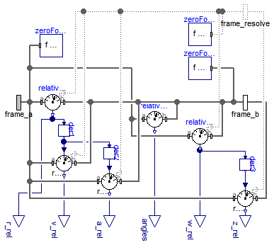
Relative kinematic quantities between frame_a and frame_b are determined and provided at the conditional output signal connectors. For example, if parameter "get_r_rel = true", the connector "r_rel" is enabled and contains the relative vector from frame_a to frame_b. The following quantities can be provided as output signals:
Via parameter resolveInFrame it is defined, in which frame a vector is resolved (before differentiation):
| resolveInFrame = Types.ResolveInFrameAB. | Meaning |
|---|---|
| world | Resolve vectors in world frame |
| frame_a | Resolve vectors in frame_a |
| frame_b | Resolve vectors in frame_b |
| frame_resolve | Resolve vectors in frame_resolve |
If resolveInFrame = Types.ResolveInFrameAB.frame_resolve, the conditional connector "frame_resolve" is enabled and the vectors are resolved in the frame, to which frame_resolve is connected. Note, if this connector is enabled, it must be connected.
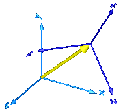
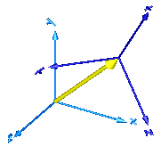
In the following figure the animation of a RelativeSensor component is shown. The light blue coordinate system is frame_a, the dark blue coordinate system is frame_b, and the yellow arrow is the animated sensor.
Note, derivatives of relative kinematic quantities are always performed with respect to the frame, in which the vector to be differentiated is resolved. After differentiation, it is possible via parameter resolveInFrameAfterDifferentiation (in the "Advanced" menu) to resolve the differentiated vector in another frame.
For example, if resolveInFrame = Types.ResolveInFrameAB.frame_b, then
   r_rel = resolve2(frame_b.R, frame_b.r_0 - frame_a.r0);
   v_rel = der(r_rel);
is returned (r_rel = resolve2(frame_b.R, frame_b.r_0 - frame_a.r0)), i.e., the derivative of the relative distance from frame_a to frame_b, resolved in frame_b. If resolveInFrameAfterDifferentiation = Types.ResolveInFrameAB.world, then v_rel is additionally transformed to:
v_rel = resolve1(frame_b.R, der(r_rel))
The cut-force and the cut-torque in frame_resolve are always zero, whether frame_resolve is connected or not.
If get_angles = true, the 3 angles to rotate frame_a into frame_b along the axes defined by parameter sequence are returned. For example, if sequence = {3,1,2} then frame_a is rotated around angles[1] along the z-axis, afterwards it is rotated around angles[2] along the x-axis, and finally it is rotated around angles[3] along the y-axis and is then identical to frame_b. The 3 angles are returned in the range
-p <= angles[i] <= p
There are two solutions for "angles[1]" in this range. Via parameter guessAngle1 (default = 0) the returned solution is selected such that |angles[1] - guessAngle1| is minimal. The relative transformation matrix between frame_a and frame_b may be in a singular configuration with respect to "sequence", i.e., there is an infinite number of angle values leading to the same relative transformation matrix. In this case, the returned solution is selected by setting angles[1] = guessAngle1. Then angles[2] and angles[3] can be uniquely determined in the above range.
The parameter sequence has the restriction that only values 1,2,3 can be used and that sequence[1] ≠ sequence[2] and sequence[2] ≠ sequence[3]. Often used values are:
  sequence = {1,2,3}  // Cardan or Tait-Bryan angle sequence
           = {3,1,3}  // Euler angle sequence
           = {3,2,1}
Extends from Modelica.Mechanics.MultiBody.Sensors.Internal.PartialRelativeSensor (Partial relative sensor model for sensors defined by components).
| Type | Name | Default | Description |
|---|---|---|---|
| Boolean | animation | true | = true, if animation shall be enabled (show arrow) |
| ResolveInFrameAB | resolveInFrame | Modelica.Mechanics.MultiBody... | Frame in which vectors are resolved before differentiation (1: world, 2: frame_a, 3: frame_b, 4: frame_resolve) |
| Boolean | get_r_rel | false | = true, to measure the relative position vector from the origin of frame_a to frame_b |
| Boolean | get_v_rel | false | = true, to measure the relative velocity of the origin of frame_b with respect to frame_a |
| Boolean | get_a_rel | false | = true, to measure the relative acceleration of the origin of frame_b with respect to frame_a |
| Boolean | get_w_rel | false | = true, to measure the relative angular velocity of frame_b with respect to frame_a |
| Boolean | get_z_rel | false | = true, to measure the relative angular acceleration of frame_b with respect to frame_a |
| 3 angles to rotate frame_a into frame_b along the axes defined in "sequence" | |||
| Boolean | get_angles | false | = true, to measure the 3 rotation angles |
| RotationSequence | sequence | {1,2,3} | If get_angles=true: Angles are returned to rotate frame_a around axes sequence[1], sequence[2] and finally sequence[3] into frame_b |
| Angle | guessAngle1 | 0 | If get_angles=true: Select angles[1] such that abs(angles[1] - guessAngle1) is a minimum [rad] |
| Animation | |||
| if animation = true | |||
| Diameter | arrowDiameter | world.defaultArrowDiameter | Diameter of relative arrow from frame_a to frame_b [m] |
| Color | arrowColor | Modelica.Mechanics.MultiBody... | Color of relative arrow from frame_a to frame_b |
| SpecularCoefficient | specularCoefficient | world.defaultSpecularCoeffic... | Reflection of ambient light (= 0: light is completely absorbed) |
| Advanced | |||
| if get_v_rel or get_a_rel or get_z_rel | |||
| ResolveInFrameAB | resolveInFrameAfterDifferentiation | resolveInFrame | Frame in which vectors are resolved after differentiation (1: world, 2: frame_a, 3: frame_b, 4: frame_resolve) |
| Type | Name | Description |
|---|---|---|
| Frame_a | frame_a | Coordinate system a |
| Frame_b | frame_b | Coordinate system b |
| Frame_resolve | frame_resolve | If resolveInFrame = Types.ResolveInFrameAB.frame_resolve, the output signals are resolved in this frame |
| output RealOutput | r_rel[3] | Relative position vector frame_b.r_0 - frame_a.r_0 resolved in frame defined by resolveInFrame [m] |
| output RealOutput | v_rel[3] | Relative velocity vector [m/s] |
| output RealOutput | a_rel[3] | Relative acceleration vector [m/s2] |
| output RealOutput | angles[3] | Angles to rotate frame_a into frame_b via 'sequence' [rad] |
| output RealOutput | w_rel[3] | Relative angular velocity vector [1/s] |
| output RealOutput | z_rel[3] | Relative angular acceleration vector [1/s2] |
model RelativeSensor "Measure relative kinematic quantities between two frame connectors" import SI = Modelica.SIunits; extends Modelica.Mechanics.MultiBody.Sensors.Internal.PartialRelativeSensor;Interfaces.Frame_resolve frame_resolve if resolveInFrame == Modelica.Mechanics.MultiBody.Types.ResolveInFrameAB.frame_resolve or resolveInFrameAfterDifferentiation == Modelica.Mechanics.MultiBody.Types.ResolveInFrameAB.frame_resolve "If resolveInFrame = Types.ResolveInFrameAB.frame_resolve, the output signals are resolved in this frame"; parameter Boolean animation=true "= true, if animation shall be enabled (show arrow)"; parameter Modelica.Mechanics.MultiBody.Types.ResolveInFrameAB resolveInFrame= Modelica.Mechanics.MultiBody.Types.ResolveInFrameAB.frame_a "Frame in which vectors are resolved before differentiation (1: world, 2: frame_a, 3: frame_b, 4: frame_resolve)"; parameter Boolean get_r_rel=false "= true, to measure the relative position vector from the origin of frame_a to frame_b"; parameter Boolean get_v_rel=false "= true, to measure the relative velocity of the origin of frame_b with respect to frame_a"; parameter Boolean get_a_rel=false "= true, to measure the relative acceleration of the origin of frame_b with respect to frame_a"; parameter Boolean get_w_rel=false "= true, to measure the relative angular velocity of frame_b with respect to frame_a"; parameter Boolean get_z_rel=false "= true, to measure the relative angular acceleration of frame_b with respect to frame_a"; parameter Boolean get_angles=false "= true, to measure the 3 rotation angles"; parameter Types.RotationSequence sequence( min={1,1,1}, max={3,3,3}) = {1,2,3} "If get_angles=true: Angles are returned to rotate frame_a around axes sequence[1], sequence[2] and finally sequence[3] into frame_b"; parameter SI.Angle guessAngle1=0 "If get_angles=true: Select angles[1] such that abs(angles[1] - guessAngle1) is a minimum"; input SI.Diameter arrowDiameter=world.defaultArrowDiameter "Diameter of relative arrow from frame_a to frame_b"; input Types.Color arrowColor=Modelica.Mechanics.MultiBody.Types.Defaults.SensorColor "Color of relative arrow from frame_a to frame_b"; input Types.SpecularCoefficient specularCoefficient = world.defaultSpecularCoefficient "Reflection of ambient light (= 0: light is completely absorbed)"; parameter Modelica.Mechanics.MultiBody.Types.ResolveInFrameAB resolveInFrameAfterDifferentiation = resolveInFrame "Frame in which vectors are resolved after differentiation (1: world, 2: frame_a, 3: frame_b, 4: frame_resolve)";Blocks.Interfaces.RealOutput r_rel[3](each final quantity="Position", each final unit = "m") if get_r_rel "Relative position vector frame_b.r_0 - frame_a.r_0 resolved in frame defined by resolveInFrame"; Blocks.Interfaces.RealOutput v_rel[3](each final quantity="Velocity", each final unit = "m/s") if get_v_rel "Relative velocity vector"; Blocks.Interfaces.RealOutput a_rel[3](each final quantity="Acceleration", each final unit="m/s2") if get_a_rel "Relative acceleration vector"; Blocks.Interfaces.RealOutput angles[3](each final quantity="Angles", each final unit = "rad", each displayUnit = "deg") if get_angles "Angles to rotate frame_a into frame_b via 'sequence'"; Blocks.Interfaces.RealOutput w_rel[3](each final quantity="AngularVelocity", each final unit = "1/s") if get_w_rel "Relative angular velocity vector"; Blocks.Interfaces.RealOutput z_rel[3](each final quantity="AngularAcceleration", each final unit = "1/s2") if get_z_rel "Relative angular acceleration vector"; protected RelativePosition relativePosition( resolveInFrame=resolveInFrame) if get_r_rel or get_v_rel or get_a_rel; protected Blocks.Continuous.Der der1[3] if get_v_rel or get_a_rel; Blocks.Continuous.Der der2[3] if get_a_rel; Modelica.Mechanics.MultiBody.Sensors.RelativeAngles relativeAngles( sequence=sequence, guessAngle1= guessAngle1) if get_angles; RelativeAngularVelocity relativeAngularVelocity( resolveInFrame= resolveInFrame) if get_w_rel or get_z_rel; protected Blocks.Continuous.Der der3[3] if get_z_rel; Internal.ZeroForceAndTorque zeroForce1; Internal.ZeroForceAndTorque zeroForce2; Internal.ZeroForceAndTorque zeroForce3 if resolveInFrame == Modelica.Mechanics.MultiBody.Types.ResolveInFrameAB.frame_resolve; protected Modelica.Mechanics.MultiBody.Sensors.TansformRelativeVector transformVector_v_rel( frame_r_in=resolveInFrame, frame_r_out=resolveInFrameAfterDifferentiation) if get_v_rel; Modelica.Mechanics.MultiBody.Sensors.TansformRelativeVector transformVector_a_rel( frame_r_in=resolveInFrame, frame_r_out=resolveInFrameAfterDifferentiation) if get_a_rel; Modelica.Mechanics.MultiBody.Sensors.TansformRelativeVector transformVector_z_rel( frame_r_in=resolveInFrame, frame_r_out=resolveInFrameAfterDifferentiation) if get_z_rel; protected outer Modelica.Mechanics.MultiBody.World world; Modelica.Mechanics.MultiBody.Visualizers.Advanced.Arrow arrow( r=frame_a.r_0, r_head=frame_b.r_0 - frame_a.r_0, diameter=arrowDiameter, color=arrowColor, specularCoefficient) if world.enableAnimation and animation; equationconnect(relativePosition.frame_a, frame_a); connect(relativePosition.frame_b, frame_b); connect(relativePosition.r_rel, r_rel); connect(zeroForce1.frame_a, frame_a); connect(zeroForce2.frame_a, frame_b); connect(relativePosition.r_rel, der1.u); connect(der2.u, der1.y); connect(relativeAngles.frame_a, frame_a); connect(relativeAngles.frame_b, frame_b); connect(relativeAngles.angles, angles); connect(relativeAngularVelocity.frame_b, frame_b); connect(relativeAngularVelocity.frame_a, frame_a); connect(relativeAngularVelocity.w_rel, w_rel); connect(relativeAngularVelocity.w_rel, der3.u); connect(der1.y, transformVector_v_rel.r_in); connect(transformVector_v_rel.r_out, v_rel); connect(transformVector_v_rel.frame_a, frame_a); connect(transformVector_v_rel.frame_b, frame_b); connect(transformVector_v_rel.frame_resolve, frame_resolve); connect(frame_resolve, relativePosition.frame_resolve); connect(frame_resolve, zeroForce3.frame_a); connect(relativeAngularVelocity.frame_resolve, frame_resolve); connect(der2.y, transformVector_a_rel.r_in); connect(transformVector_a_rel.frame_a, frame_a); connect(transformVector_a_rel.frame_b, frame_b); connect(transformVector_a_rel.frame_resolve, frame_resolve); connect(transformVector_a_rel.r_out, a_rel); connect(der3.y, transformVector_z_rel.r_in); connect(transformVector_z_rel.r_out, z_rel); connect(transformVector_z_rel.frame_a, frame_a); connect(transformVector_z_rel.frame_b, frame_b); connect(transformVector_z_rel.frame_resolve, frame_resolve); end RelativeSensor;
 Modelica.Mechanics.MultiBody.Sensors.AbsolutePosition
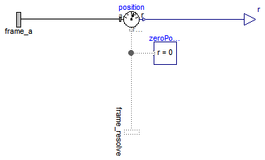
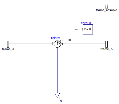
The absolute position vector of the origin of frame_a is determined and provided at the output signal connector r.
Via parameter resolveInFrame it is defined, in which frame the position vector is resolved:
| resolveInFrame = Types.ResolveInFrameA. | Meaning |
|---|---|
| world | Resolve vector in world frame |
| frame_a | Resolve vector in frame_a |
| frame_resolve | Resolve vector in frame_resolve |
If resolveInFrame = Types.ResolveInFrameA.frame_resolve, the conditional connector "frame_resolve" is enabled and r is resolved in the frame, to which frame_resolve is connected. Note, if this connector is enabled, it must be connected.
Example: If resolveInFrame = Types.ResolveInFrameA.frame_a, the output vector is computed as:
r = MultiBody.Frames.resolve2(frame_a.R, frame_b.r_0);
Extends from Internal.PartialAbsoluteSensor (Partial absolute sensor model for sensors defined by components).
| Type | Name | Default | Description |
|---|---|---|---|
| ResolveInFrameA | resolveInFrame | Modelica.Mechanics.MultiBody... | Frame in which output vector r shall be resolved (1: world, 2: frame_a, 3:frame_resolve) |
| Type | Name | Description |
|---|---|---|
| Frame_a | frame_a | Coordinate system at which the kinematic quantities are measured |
| output RealOutput | r[3] | Absolute position vector resolved in frame defined by resolveInFrame [m] |
| Frame_resolve | frame_resolve | Coordinate system in which output vector r is optionally resolved |
model AbsolutePosition "Measure absolute position vector of the origin of a frame connector" extends Internal.PartialAbsoluteSensor;Blocks.Interfaces.RealOutput r[3](each final quantity="Position", each final unit = "m") "Absolute position vector resolved in frame defined by resolveInFrame"; Modelica.Mechanics.MultiBody.Interfaces.Frame_resolve frame_resolve if resolveInFrame == Modelica.Mechanics.MultiBody.Types.ResolveInFrameA.frame_resolve "Coordinate system in which output vector r is optionally resolved"; parameter Modelica.Mechanics.MultiBody.Types.ResolveInFrameA resolveInFrame= Modelica.Mechanics.MultiBody.Types.ResolveInFrameA.frame_a "Frame in which output vector r shall be resolved (1: world, 2: frame_a, 3:frame_resolve)";protected Internal.BasicAbsolutePosition position(resolveInFrame=resolveInFrame); Modelica.Mechanics.MultiBody.Interfaces.ZeroPosition zeroPosition if not (resolveInFrame == Modelica.Mechanics.MultiBody.Types.ResolveInFrameA.frame_resolve); equationconnect(position.frame_resolve, frame_resolve); connect(zeroPosition.frame_resolve, position.frame_resolve); connect(position.r, r); connect(position.frame_a, frame_a); end AbsolutePosition;
 Modelica.Mechanics.MultiBody.Sensors.AbsoluteVelocity
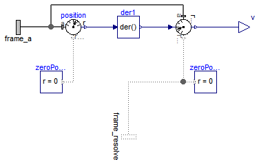
The absolute velocity vector of the origin of frame_a is determined and provided at the output signal connector v.
Via parameter resolveInFrame it is defined, in which frame the velocity vector is resolved:
| resolveInFrame = Types.ResolveInFrameA. | Meaning |
|---|---|
| world | Resolve vector in world frame |
| frame_a | Resolve vector in frame_a |
| frame_resolve | Resolve vector in frame_resolve |
If resolveInFrame = Types.ResolveInFrameA.frame_resolve, the conditional connector "frame_resolve" is enabled and v is resolved in the frame, to which frame_resolve is connected. Note, if this connector is enabled, it must be connected.
Example: If resolveInFrame = Types.ResolveInFrameA.frame_a, the output vector is computed as:
    v0 = der(frame_a.r_0);
    v  = MultiBody.Frames.resolve2(frame_a.R, v0);
Extends from Internal.PartialAbsoluteSensor (Partial absolute sensor model for sensors defined by components).
| Type | Name | Default | Description |
|---|---|---|---|
| ResolveInFrameA | resolveInFrame | Modelica.Mechanics.MultiBody... | Frame in which output vector v shall be resolved (1: world, 2: frame_a, 3: frame_resolve) |
| Type | Name | Description |
|---|---|---|
| Frame_a | frame_a | Coordinate system at which the kinematic quantities are measured |
| output RealOutput | v[3] | Absolute velocity vector resolved in frame defined by resolveInFrame [m/s] |
| Frame_resolve | frame_resolve | Coordinate system in which output vector v is optionally resolved |
model AbsoluteVelocity "Measure absolute velocity vector of origin of frame connector" extends Internal.PartialAbsoluteSensor;Blocks.Interfaces.RealOutput v[3](each final quantity="Velocity", each final unit = "m/s") "Absolute velocity vector resolved in frame defined by resolveInFrame"; Modelica.Mechanics.MultiBody.Interfaces.Frame_resolve frame_resolve if resolveInFrame == Modelica.Mechanics.MultiBody.Types.ResolveInFrameA.frame_resolve "Coordinate system in which output vector v is optionally resolved"; parameter Modelica.Mechanics.MultiBody.Types.ResolveInFrameA resolveInFrame= Modelica.Mechanics.MultiBody.Types.ResolveInFrameA.frame_a "Frame in which output vector v shall be resolved (1: world, 2: frame_a, 3: frame_resolve)";protected Internal.BasicAbsolutePosition position(resolveInFrame=Modelica.Mechanics.MultiBody.Types.ResolveInFrameA.world); Blocks.Continuous.Der der1[3]; TansformAbsoluteVector tansformAbsoluteVector( frame_r_in=Modelica.Mechanics.MultiBody.Types.ResolveInFrameA.world, frame_r_out=resolveInFrame); Modelica.Mechanics.MultiBody.Interfaces.ZeroPosition zeroPosition; Modelica.Mechanics.MultiBody.Interfaces.ZeroPosition zeroPosition1 if not ( resolveInFrame == Modelica.Mechanics.MultiBody.Types.ResolveInFrameA.frame_resolve); equationconnect(position.r, der1.u); connect(position.frame_a, frame_a); connect(der1.y, tansformAbsoluteVector.r_in); connect(tansformAbsoluteVector.r_out, v); connect(zeroPosition.frame_resolve, position.frame_resolve); connect(tansformAbsoluteVector.frame_a, frame_a); connect(tansformAbsoluteVector.frame_resolve, zeroPosition1.frame_resolve); connect(tansformAbsoluteVector.frame_resolve, frame_resolve); end AbsoluteVelocity;
 Modelica.Mechanics.MultiBody.Sensors.AbsoluteAngles
-p <= angles[i] <= p
There are two solutions for "angles[1]" in this range. Via parameter guessAngle1 (default = 0) the returned solution is selected such that |angles[1] - guessAngle1| is minimal. The transformation matrix between the world frame and frame_a may be in a singular configuration with respect to "sequence", i.e., there is an infinite number of angle values leading to the same relative transformation matrix. In this case, the returned solution is selected by setting angles[1] = guessAngle1. Then angles[2] and angles[3] can be uniquely determined in the above range.
The parameter sequence has the restriction that only values 1,2,3 can be used and that sequence[1] ≠ sequence[2] and sequence[2] ≠ sequence[3]. Often used values are:
  sequence = {1,2,3}  // Cardan or Tait-Bryan angle sequence
           = {3,1,3}  // Euler angle sequence
           = {3,2,1}
Extends from Modelica.Icons.RotationalSensor (Icon representing a round measurement device).
| Type | Name | Default | Description |
|---|---|---|---|
| RotationSequence | sequence | {1,2,3} | Angles are returned to rotate world frame around axes sequence[1], sequence[2] and finally sequence[3] into frame_a |
| Angle | guessAngle1 | 0 | Select angles[1] such that abs(angles[1] - guessAngle1) is a minimum [rad] |
| Type | Name | Description |
|---|---|---|
| Frame_a | frame_a | Coordinate system a from which the angles shall be determined |
| output RealOutput | angles[3] | Angles to rotate world frame into frame_a via 'sequence' [rad] |
model AbsoluteAngles "Measure absolute angles between frame connector and the world frame" extends Modelica.Icons.RotationalSensor;Modelica.Mechanics.MultiBody.Interfaces.Frame_a frame_a "Coordinate system a from which the angles shall be determined"; Modelica.Blocks.Interfaces.RealOutput angles[3](each final quantity="Angles", each final unit = "rad", each displayUnit = "deg") "Angles to rotate world frame into frame_a via 'sequence'"; parameter MultiBody.Types.RotationSequence sequence( min={1,1,1}, max={3,3,3})={1,2,3} "Angles are returned to rotate world frame around axes sequence[1], sequence[2] and finally sequence[3] into frame_a"; parameter SI.Angle guessAngle1=0 "Select angles[1] such that abs(angles[1] - guessAngle1) is a minimum"; equation frame_a.f = zeros(3); frame_a.t = zeros(3); angles = MultiBody.Frames.axesRotationsAngles( frame_a.R, sequence, guessAngle1);end AbsoluteAngles;
 Modelica.Mechanics.MultiBody.Sensors.AbsoluteAngularVelocity
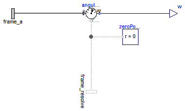
The absolute angular velocity of frame_a with respect to the world frame is determined and provided at the output signal connector w.
Via parameter resolveInFrame it is defined, in which frame the angular velocity is resolved:
| resolveInFrame = Types.ResolveInFrameAB. | Meaning |
|---|---|
| world | Resolve vector in world frame |
| frame_a | Resolve vector in frame_a |
| frame_resolve | Resolve vector in frame_resolve |
If resolveInFrame = Types.ResolveInFrameA.frame_resolve, the conditional connector "frame_resolve" is enabled and w is resolved in the frame, to which frame_resolve is connected. Note, if this connector is enabled, it must be connected.
Example: If resolveInFrame = Types.ResolveInFrameA.frame_a, the output vector is computed as:
w = MultiBody.Frames.angularVelocity2(frame_a.R);
Extends from Internal.PartialAbsoluteSensor (Partial absolute sensor model for sensors defined by components).
| Type | Name | Default | Description |
|---|---|---|---|
| ResolveInFrameA | resolveInFrame | Modelica.Mechanics.MultiBody... | Frame in which output vector w shall be resolved (1: world, 2: frame_a, 3: frame_resolve) |
| Type | Name | Description |
|---|---|---|
| Frame_a | frame_a | Coordinate system at which the kinematic quantities are measured |
| output RealOutput | w[3] | Absolute angular velocity vector of frame_a with respect to world frame, resolved in frame defined by resolveInFrame [1/s] |
| Frame_resolve | frame_resolve | Coordinate system in which w is optionally resolved |
model AbsoluteAngularVelocity "Measure absolute angular velocity of frame connector" extends Internal.PartialAbsoluteSensor;Blocks.Interfaces.RealOutput w[3](each final quantity="AngularVelocity", each final unit = "1/s") "Absolute angular velocity vector of frame_a with respect to world frame, resolved in frame defined by resolveInFrame"; Modelica.Mechanics.MultiBody.Interfaces.Frame_resolve frame_resolve if resolveInFrame == Modelica.Mechanics.MultiBody.Types.ResolveInFrameA.frame_resolve "Coordinate system in which w is optionally resolved"; parameter Modelica.Mechanics.MultiBody.Types.ResolveInFrameA resolveInFrame= Modelica.Mechanics.MultiBody.Types.ResolveInFrameA.frame_a "Frame in which output vector w shall be resolved (1: world, 2: frame_a, 3: frame_resolve)";protected Internal.BasicAbsoluteAngularVelocity angularVelocity(resolveInFrame= resolveInFrame); Modelica.Mechanics.MultiBody.Interfaces.ZeroPosition zeroPosition if not (resolveInFrame == Modelica.Mechanics.MultiBody.Types.ResolveInFrameA.frame_resolve); equationconnect(angularVelocity.frame_resolve, frame_resolve); connect(zeroPosition.frame_resolve, angularVelocity.frame_resolve); connect(angularVelocity.w, w); connect(angularVelocity.frame_a, frame_a); end AbsoluteAngularVelocity;
 Modelica.Mechanics.MultiBody.Sensors.RelativePosition
The relative position vector between the origins of frame_a and frame_b are determined and provided at the output signal connector r_rel.
Via parameter resolveInFrame it is defined, in which frame the position vector is resolved:
| resolveInFrame = Types.ResolveInFrameAB. | Meaning |
|---|---|
| world | Resolve vector in world frame |
| frame_a | Resolve vector in frame_a |
| frame_b | Resolve vector in frame_b |
| frame_resolve | Resolve vector in frame_resolve |
If resolveInFrame = Types.ResolveInFrameAB.frame_resolve, the conditional connector "frame_resolve" is enabled and r_rel is resolved in the frame, to which frame_resolve is connected. Note, if this connector is enabled, it must be connected.
Example: If resolveInFrame = Types.ResolveInFrameAB.frame_a, the output vector is computed as:
r_rel = MultiBody.Frames.resolve2(frame_a.R, frame_b.r_0 - frame_a.r_0);
Extends from Internal.PartialRelativeSensor (Partial relative sensor model for sensors defined by components).
| Type | Name | Default | Description |
|---|---|---|---|
| ResolveInFrameAB | resolveInFrame | Modelica.Mechanics.MultiBody... | Frame in which output vector r_rel shall be resolved (1: world, 2: frame_a, 3: frame_b, 4: frame_resolve) |
| Type | Name | Description |
|---|---|---|
| Frame_a | frame_a | Coordinate system a |
| Frame_b | frame_b | Coordinate system b |
| output RealOutput | r_rel[3] | Relative position vector resolved in frame defined by resolveInFrame |
| Frame_resolve | frame_resolve | Coordinate system in which r_rel is optionally resolved |
model RelativePosition "Measure relative position vector between the origins of two frame connectors" extends Internal.PartialRelativeSensor;Blocks.Interfaces.RealOutput r_rel[3] "Relative position vector resolved in frame defined by resolveInFrame"; Modelica.Mechanics.MultiBody.Interfaces.Frame_resolve frame_resolve if resolveInFrame == Modelica.Mechanics.MultiBody.Types.ResolveInFrameAB.frame_resolve "Coordinate system in which r_rel is optionally resolved"; parameter Modelica.Mechanics.MultiBody.Types.ResolveInFrameAB resolveInFrame= Modelica.Mechanics.MultiBody.Types.ResolveInFrameAB.frame_a "Frame in which output vector r_rel shall be resolved (1: world, 2: frame_a, 3: frame_b, 4: frame_resolve)";protected Internal.BasicRelativePosition relativePosition(resolveInFrame=resolveInFrame); Modelica.Mechanics.MultiBody.Interfaces.ZeroPosition zeroPosition if not (resolveInFrame == Modelica.Mechanics.MultiBody.Types.ResolveInFrameAB.frame_resolve); equationconnect(relativePosition.frame_a, frame_a); connect(relativePosition.frame_b, frame_b); connect(relativePosition.frame_resolve, frame_resolve); connect(zeroPosition.frame_resolve, relativePosition.frame_resolve); connect(relativePosition.r_rel, r_rel); end RelativePosition;
 Modelica.Mechanics.MultiBody.Sensors.RelativeVelocity
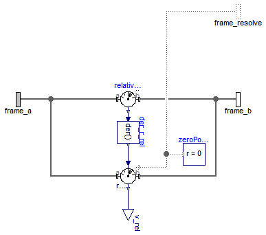
The relative velocity vector between the origins of frame_a and of frame_b are determined and provided at the output signal connector v_rel. This vector is defined as:
    r_rel = MultiBody.Frames.resolve2(frame_a.R, frame_b.r_0 - frame_a.r_0);
    v_rel = der(r_rel);
Via parameter resolveInFrame it is defined, in which frame the velocity vector is resolved:
| resolveInFrame = Types.ResolveInFrameAB. | Meaning |
|---|---|
| world | Resolve vector in world frame |
| frame_a | Resolve vector in frame_a |
| frame_b | Resolve vector in frame_b |
| frame_resolve | Resolve vector in frame_resolve |
If resolveInFrame = Types.ResolveInFrameAB.frame_resolve, the conditional connector "frame_resolve" is enabled and v_rel is resolved in the frame, to which frame_resolve is connected. Note, if this connector is enabled, it must be connected.
Example: If resolveInFrame = Types.ResolveInFrameAB.frame_b, the output vector is computed as:
    r_rel   = MultiBody.Frames.resolve2(frame_a.R, frame_b.r_0 - frame_a.r_0);
    v_rel_a = der(r_rel);
    v_rel   = MultiBody.Frames.resolveRelative(frame_a.R, frame_b.R, v_rel_a);
Extends from Internal.PartialRelativeSensor (Partial relative sensor model for sensors defined by components).
| Type | Name | Default | Description |
|---|---|---|---|
| ResolveInFrameAB | resolveInFrame | Modelica.Mechanics.MultiBody... | Frame in which output vector v_rel shall be resolved (1: world, 2: frame_a, 3: frame_b, 4: frame_resolve) |
| Type | Name | Description |
|---|---|---|
| Frame_a | frame_a | Coordinate system a |
| Frame_b | frame_b | Coordinate system b |
| output RealOutput | v_rel[3] | Relative velocity vector resolved in frame defined by resolveInFrame [m/s] |
| Frame_resolve | frame_resolve | Coordinate system in which v_rel is optionally resolved |
model RelativeVelocity "Measure relative velocity vector between the origins of two frame connectors" extends Internal.PartialRelativeSensor;Modelica.Blocks.Interfaces.RealOutput v_rel[3](each final quantity="Velocity", each final unit = "m/s") "Relative velocity vector resolved in frame defined by resolveInFrame"; Modelica.Mechanics.MultiBody.Interfaces.Frame_resolve frame_resolve if resolveInFrame == Modelica.Mechanics.MultiBody.Types.ResolveInFrameAB.frame_resolve "Coordinate system in which v_rel is optionally resolved"; parameter Modelica.Mechanics.MultiBody.Types.ResolveInFrameAB resolveInFrame= Modelica.Mechanics.MultiBody.Types.ResolveInFrameAB.frame_a "Frame in which output vector v_rel shall be resolved (1: world, 2: frame_a, 3: frame_b, 4: frame_resolve)";protected RelativePosition relativePosition(resolveInFrame=Modelica.Mechanics.MultiBody.Types.ResolveInFrameAB.frame_a); Modelica.Mechanics.MultiBody.Interfaces.ZeroPosition zeroPosition if not (resolveInFrame == Modelica.Mechanics.MultiBody.Types.ResolveInFrameAB.frame_resolve); Modelica.Blocks.Continuous.Der der_r_rel[3]; TansformRelativeVector tansformRelativeVector( frame_r_in= Modelica.Mechanics.MultiBody.Types.ResolveInFrameAB.frame_a, frame_r_out=resolveInFrame); equationconnect(relativePosition.frame_a, frame_a); connect(relativePosition.frame_b, frame_b); connect(relativePosition.r_rel, der_r_rel.u); connect(der_r_rel.y, tansformRelativeVector.r_in); connect(tansformRelativeVector.r_out, v_rel); connect(tansformRelativeVector.frame_a, frame_a); connect(tansformRelativeVector.frame_b, frame_b); connect(tansformRelativeVector.frame_resolve, frame_resolve); connect(zeroPosition.frame_resolve, tansformRelativeVector.frame_resolve); end RelativeVelocity;
 Modelica.Mechanics.MultiBody.Sensors.RelativeAngles
-p <= angles[i] <= p
There are two solutions for "angles[1]" in this range. Via parameter guessAngle1 (default = 0) the returned solution is selected such that |angles[1] - guessAngle1| is minimal. The relative transformation matrix between frame_a and frame_b may be in a singular configuration with respect to "sequence", i.e., there is an infinite number of angle values leading to the same relative transformation matrix. In this case, the returned solution is selected by setting angles[1] = guessAngle1. Then angles[2] and angles[3] can be uniquely determined in the above range.
The parameter sequence has the restriction that only values 1,2,3 can be used and that sequence[1] ≠ sequence[2] and sequence[2] ≠ sequence[3]. Often used values are:
  sequence = {1,2,3}  // Cardan or Tait-Bryan angle sequence
           = {3,1,3}  // Euler angle sequence
           = {3,2,1}
Extends from Modelica.Icons.RotationalSensor (Icon representing a round measurement device).
| Type | Name | Default | Description |
|---|---|---|---|
| RotationSequence | sequence | {1,2,3} | Angles are returned to rotate frame_a around axes sequence[1], sequence[2] and finally sequence[3] into frame_b |
| Angle | guessAngle1 | 0 | Select angles[1] such that abs(angles[1] - guessAngle1) is a minimum [rad] |
| Type | Name | Description |
|---|---|---|
| Frame_a | frame_a | Coordinate system a |
| Frame_b | frame_b | Coordinate system b |
| output RealOutput | angles[3] | Angles to rotate frame_a into frame_b via 'sequence' [rad] |
model RelativeAngles "Measure relative angles between two frame connectors" extends Modelica.Icons.RotationalSensor;Modelica.Mechanics.MultiBody.Interfaces.Frame_a frame_a "Coordinate system a"; Modelica.Mechanics.MultiBody.Interfaces.Frame_b frame_b "Coordinate system b"; Modelica.Blocks.Interfaces.RealOutput angles[3](each final quantity="Angles", each final unit = "rad", displayUnit="deg") "Angles to rotate frame_a into frame_b via 'sequence'"; parameter MultiBody.Types.RotationSequence sequence( min={1,1,1}, max={3,3,3})={1,2,3} "Angles are returned to rotate frame_a around axes sequence[1], sequence[2] and finally sequence[3] into frame_b"; parameter SI.Angle guessAngle1=0 "Select angles[1] such that abs(angles[1] - guessAngle1) is a minimum"; Modelica.Mechanics.MultiBody.Frames.Orientation R_rel "Relative orientation object from frame_a to frame_b"; equation frame_a.f = zeros(3); frame_a.t = zeros(3); frame_b.f = zeros(3); frame_b.t = zeros(3); R_rel = Modelica.Mechanics.MultiBody.Frames.relativeRotation(frame_a.R, frame_b.R); angles = MultiBody.Frames.axesRotationsAngles( R_rel, sequence, guessAngle1);end RelativeAngles;
 Modelica.Mechanics.MultiBody.Sensors.RelativeAngularVelocity

The relative angular velocity between frame_a and frame_b is determined and provided at the output signal connector w_rel.
Via parameter resolveInFrame it is defined, in which frame the angular velocity is resolved:
| resolveInFrame = Types.ResolveInFrameAB. | Meaning |
|---|---|
| world | Resolve vector in world frame |
| frame_a | Resolve vector in frame_a |
| frame_b | Resolve vector in frame_b |
| frame_resolve | Resolve vector in frame_resolve |
If resolveInFrame = Types.ResolveInFrameAB.frame_resolve, the conditional connector "frame_resolve" is enabled and w_rel is resolved in the frame, to which frame_resolve is connected. Note, if this connector is enabled, it must be connected.
Example: If resolveInFrame = Types.ResolveInFrameAB.frame_a, the output vector is computed as:
    // Relative orientation object from frame_a to frame_b
    R_rel = MultiBody.Frames.relativeRotation(frame_a.R, frame_b.R);

    // Angular velocity resolved in frame_a
    w_rel = MultiBody.Frames.angularVelocity1(R_rel);
Extends from Internal.PartialRelativeSensor (Partial relative sensor model for sensors defined by components).
| Type | Name | Default | Description |
|---|---|---|---|
| ResolveInFrameAB | resolveInFrame | Modelica.Mechanics.MultiBody... | Frame in which output vector w_rel shall be resolved (1: world, 2: frame_a, 3: frame_b, 4: frame_resolve) |
| Type | Name | Description |
|---|---|---|
| Frame_a | frame_a | Coordinate system a |
| Frame_b | frame_b | Coordinate system b |
| output RealOutput | w_rel[3] | Relative angular velocity vector between frame_a and frame_b resolved in frame defined by resolveInFrame [1/s] |
| Frame_resolve | frame_resolve | Coordinate system in which w_rel is optionally resolved |
model RelativeAngularVelocity "Measure relative angular velocity between two frame connectors" extends Internal.PartialRelativeSensor;Blocks.Interfaces.RealOutput w_rel[3](each final quantity="AngularVelocity", each final unit = "1/s") "Relative angular velocity vector between frame_a and frame_b resolved in frame defined by resolveInFrame"; Modelica.Mechanics.MultiBody.Interfaces.Frame_resolve frame_resolve if resolveInFrame == Modelica.Mechanics.MultiBody.Types.ResolveInFrameAB.frame_resolve "Coordinate system in which w_rel is optionally resolved"; parameter Modelica.Mechanics.MultiBody.Types.ResolveInFrameAB resolveInFrame= Modelica.Mechanics.MultiBody.Types.ResolveInFrameAB.frame_a "Frame in which output vector w_rel shall be resolved (1: world, 2: frame_a, 3: frame_b, 4: frame_resolve)";protected Internal.BasicRelativeAngularVelocity relativeAngularVelocity(resolveInFrame= resolveInFrame); Modelica.Mechanics.MultiBody.Interfaces.ZeroPosition zeroPosition if not (resolveInFrame == Modelica.Mechanics.MultiBody.Types.ResolveInFrameAB.frame_resolve); equationconnect(relativeAngularVelocity.frame_a, frame_a); connect(relativeAngularVelocity.frame_b, frame_b); connect(relativeAngularVelocity.frame_resolve, frame_resolve); connect(zeroPosition.frame_resolve, relativeAngularVelocity.frame_resolve); connect(relativeAngularVelocity.w_rel, w_rel); end RelativeAngularVelocity;
 Modelica.Mechanics.MultiBody.Sensors.Distance
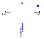
The distance between the origins of frame_a and of frame_b are determined and provided at the output signal connector distance. This distance is always positive. Derivatives of this signal can be easily obtained by connecting the block Modelica.Blocks.Continuous.Der to "distance" (this block performs analytic differentiation of the input signal using the der(..) operator).
In the following figure the animation of a Distance sensor is shown. The light blue coordinate system is frame_a, the dark blue coordinate system is frame_b, and the yellow arrow is the animated sensor.
If the distance is smaller as parameter s_small (in the "advanced" menu), it is approximated such that its derivative is finite for zero distance. Without such an approximation, the derivative would be infinite and a division by zero would occur. The approximation is performed in the following way: If distance > s_small, it is computed as sqrt(r*r) where r is the position vector from the origin of frame_a to the origin of frame_b. If the distance becomes smaller as s_small, the "sqrt()" function is approximated by a second order polynomial, such that the function value and its first derivative are identical for sqrt() and the polynomial at s_small. Futhermore, the polynomial passes through zero. The effect is, that the distance function is continuous and differentiable everywhere. The derivative at zero distance is 3/(2*s_small).
Extends from Interfaces.PartialTwoFrames (Base model for components providing two frame connectors + outer world + assert to guarantee that the component is connected), Modelica.Icons.TranslationalSensor (Icon representing a linear measurement device).
| Type | Name | Default | Description |
|---|---|---|---|
| Boolean | animation | true | = true, if animation shall be enabled (show arrow) |
| if animation = true | |||
| Diameter | arrowDiameter | world.defaultArrowDiameter | Diameter of relative arrow from frame_a to frame_b [m] |
| Color | arrowColor | Modelica.Mechanics.MultiBody... | Color of relative arrow from frame_a to frame_b |
| SpecularCoefficient | specularCoefficient | world.defaultSpecularCoeffic... | Reflection of ambient light (= 0: light is completely absorbed) |
| Advanced | |||
| Position | s_small | 1.E-10 | Prevent zero-division if distance between frame_a and frame_b is zero [m] |
| Type | Name | Description |
|---|---|---|
| Frame_a | frame_a | Coordinate system fixed to the component with one cut-force and cut-torque |
| Frame_b | frame_b | Coordinate system fixed to the component with one cut-force and cut-torque |
| output RealOutput | distance | Distance between the origin of frame_a and the origin of frame_b |
model Distance "Measure the distance between the origins of two frame connectors" import SI = Modelica.SIunits; import Modelica.Mechanics.MultiBody.Frames; import Modelica.Mechanics.MultiBody.Types; extends Interfaces.PartialTwoFrames; extends Modelica.Icons.TranslationalSensor;Modelica.Blocks.Interfaces.RealOutput distance "Distance between the origin of frame_a and the origin of frame_b"; parameter Boolean animation=true "= true, if animation shall be enabled (show arrow)"; input SI.Diameter arrowDiameter=world.defaultArrowDiameter "Diameter of relative arrow from frame_a to frame_b"; input Types.Color arrowColor=Modelica.Mechanics.MultiBody.Types.Defaults.SensorColor "Color of relative arrow from frame_a to frame_b"; input Types.SpecularCoefficient specularCoefficient = world.defaultSpecularCoefficient "Reflection of ambient light (= 0: light is completely absorbed)"; input SI.Position s_small(min=sqrt(Modelica.Constants.small))=1.E-10 "Prevent zero-division if distance between frame_a and frame_b is zero"; protected Modelica.Mechanics.MultiBody.Visualizers.Advanced.Arrow arrow( r=frame_a.r_0, r_head=frame_b.r_0 - frame_a.r_0, diameter=arrowDiameter, color=arrowColor, specularCoefficient=specularCoefficient) if world.enableAnimation and animation; protected SI.Position r_rel_0[3] = frame_b.r_0 - frame_a.r_0 "Position vector from frame_a to frame_b resolved in world frame"; SI.Area L2 = r_rel_0*r_rel_0; SI.Area s_small2 = s_small^2; equation frame_a.f = zeros(3); frame_b.f = zeros(3); frame_a.t = zeros(3); frame_b.t = zeros(3); distance = smooth(1,if noEvent(L2 > s_small2) then sqrt(L2) else L2/(2*s_small)*(3-L2/s_small2));end Distance;
 Modelica.Mechanics.MultiBody.Sensors.CutForce
The cut-force acting between the two frames to which this model is connected, is determined and provided at the output signal connector force (= frame_a.f). If parameter positiveSign = false, the negative cut-force is provided (= frame_b.f).
Via parameter resolveInFrame it is defined, in which frame the force vector is resolved:
| resolveInFrame = Types.ResolveInFrameAB. | Meaning |
|---|---|
| world | Resolve vector in world frame |
| frame_a | Resolve vector in frame_a |
| frame_b | Resolve vector in frame_b |
| frame_resolve | Resolve vector in frame_resolve |
If resolveInFrame = Types.ResolveInFrameAB.frame_resolve, the conditional connector "frame_resolve" is enabled and output force is resolved in the frame, to which frame_resolve is connected. Note, if this connector is enabled, it must be connected.
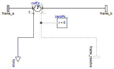
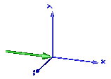
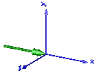
In the following figure the animation of a CutForce sensor is shown. The dark blue coordinate system is frame_b, and the green arrow is the cut force acting at frame_b and with negative sign at frame_a.
Extends from Modelica.Mechanics.MultiBody.Sensors.Internal.PartialCutForceSensor (Base model to measure the cut force and/or torque between two frames, defined by components).
| Type | Name | Default | Description |
|---|---|---|---|
| Boolean | animation | true | = true, if animation shall be enabled (show arrow) |
| Boolean | positiveSign | true | = true, if force with positive sign is returned (= frame_a.f), otherwise with negative sign (= frame_b.f) |
| ResolveInFrameA | resolveInFrame | Modelica.Mechanics.MultiBody... | Frame in which output vector(s) is/are resolved (1: world, 2: frame_a, 3: frame_resolve) |
| if animation = true | |||
| Real | N_to_m | 1000 | Force arrow scaling (length = force/N_to_m) [N/m] |
| Diameter | forceDiameter | world.defaultArrowDiameter | Diameter of force arrow [m] |
| Color | forceColor | Modelica.Mechanics.MultiBody... | Color of force arrow |
| SpecularCoefficient | specularCoefficient | world.defaultSpecularCoeffic... | Reflection of ambient light (= 0: light is completely absorbed) |
| Type | Name | Description |
|---|---|---|
| output RealOutput | force[3] | Cut force resolved in frame defined by resolveInFrame [N] |
| Frame_a | frame_a | Coordinate system a |
| Frame_b | frame_b | Coordinate system b |
| Frame_resolve | frame_resolve | Output vectors are optionally resolved in this frame (cut-force/-torque are set to zero) |
model CutForce "Measure cut force vector" import SI = Modelica.SIunits;Modelica.Blocks.Interfaces.RealOutput force[3](final quantity="Force", final unit="N") "Cut force resolved in frame defined by resolveInFrame"; parameter Boolean animation=true "= true, if animation shall be enabled (show arrow)"; parameter Boolean positiveSign=true "= true, if force with positive sign is returned (= frame_a.f), otherwise with negative sign (= frame_b.f)"; input Real N_to_m(unit="N/m") = 1000 " Force arrow scaling (length = force/N_to_m)"; input SI.Diameter forceDiameter=world.defaultArrowDiameter " Diameter of force arrow"; input Types.Color forceColor=Modelica.Mechanics.MultiBody.Types.Defaults. ForceColor " Color of force arrow"; input Types.SpecularCoefficient specularCoefficient = world.defaultSpecularCoefficient "Reflection of ambient light (= 0: light is completely absorbed)"; extends Modelica.Mechanics.MultiBody.Sensors.Internal.PartialCutForceSensor; protected SI.Position f_in_m[3]=frame_a.f*(if positiveSign then +1 else -1)/N_to_m "Force mapped from N to m for animation"; Visualizers.Advanced.Arrow forceArrow( diameter=forceDiameter, color=forceColor, specularCoefficient=specularCoefficient, R=frame_b.R, r=frame_b.r_0, r_tail=f_in_m, r_head=-f_in_m) if world.enableAnimation and animation;Internal.BasicCutForce cutForce(resolveInFrame=resolveInFrame, positiveSign= positiveSign); Modelica.Mechanics.MultiBody.Interfaces.ZeroPosition zeroPosition if not (resolveInFrame == Modelica.Mechanics.MultiBody.Types.ResolveInFrameA.frame_resolve); equationconnect(cutForce.frame_a, frame_a); connect(cutForce.frame_b, frame_b); connect(cutForce.frame_resolve, frame_resolve); connect(cutForce.force, force); connect(zeroPosition.frame_resolve, cutForce.frame_resolve); end CutForce;
 Modelica.Mechanics.MultiBody.Sensors.CutTorque
The cut-torque acting between the two frames to which this model is connected, is determined and provided at the output signal connector torque (= frame_a.t). If parameter positiveSign = false, the negative cut-torque is provided (= frame_b.t).
Via parameter resolveInFrame it is defined, in which frame the torque vector is resolved:
| resolveInFrame = Types.ResolveInFrameAB. | Meaning |
|---|---|
| world | Resolve vector in world frame |
| frame_a | Resolve vector in frame_a |
| frame_b | Resolve vector in frame_b |
| frame_resolve | Resolve vector in frame_resolve |
If resolveInFrame = Types.ResolveInFrameAB.frame_resolve, the conditional connector "frame_resolve" is enabled and output torque is resolved in the frame, to which frame_resolve is connected. Note, if this connector is enabled, it must be connected.
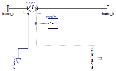
In the following figure the animation of a CutTorque sensor is shown. The dark blue coordinate system is frame_b, and the green arrow is the cut torque acting at frame_b and with negative sign at frame_a.
Extends from Modelica.Mechanics.MultiBody.Sensors.Internal.PartialCutForceSensor (Base model to measure the cut force and/or torque between two frames, defined by components).
| Type | Name | Default | Description |
|---|---|---|---|
| Boolean | animation | true | = true, if animation shall be enabled (show arrow) |
| Boolean | positiveSign | true | = true, if torque with positive sign is returned (= frame_a.t), otherwise with negative sign (= frame_b.t) |
| ResolveInFrameA | resolveInFrame | Modelica.Mechanics.MultiBody... | Frame in which output vector(s) is/are resolved (1: world, 2: frame_a, 3: frame_resolve) |
| if animation = true | |||
| Real | Nm_to_m | 1000 | Torque arrow scaling (length = torque/Nm_to_m) [N.m/m] |
| Diameter | torqueDiameter | world.defaultArrowDiameter | Diameter of torque arrow [m] |
| Color | torqueColor | Modelica.Mechanics.MultiBody... | Color of torque arrow |
| SpecularCoefficient | specularCoefficient | world.defaultSpecularCoeffic... | Reflection of ambient light (= 0: light is completely absorbed) |
| Type | Name | Description |
|---|---|---|
| output RealOutput | torque[3] | Cut torque resolved in frame defined by resolveInFrame |
| Frame_a | frame_a | Coordinate system a |
| Frame_b | frame_b | Coordinate system b |
| Frame_resolve | frame_resolve | Output vectors are optionally resolved in this frame (cut-force/-torque are set to zero) |
model CutTorque "Measure cut torque vector" import SI = Modelica.SIunits;Modelica.Blocks.Interfaces.RealOutput torque[3] "Cut torque resolved in frame defined by resolveInFrame"; parameter Boolean animation=true "= true, if animation shall be enabled (show arrow)"; parameter Boolean positiveSign=true "= true, if torque with positive sign is returned (= frame_a.t), otherwise with negative sign (= frame_b.t)"; input Real Nm_to_m(unit="N.m/m") = 1000 "Torque arrow scaling (length = torque/Nm_to_m)"; input SI.Diameter torqueDiameter=world.defaultArrowDiameter "Diameter of torque arrow"; input Types.Color torqueColor=Modelica.Mechanics.MultiBody.Types.Defaults.TorqueColor "Color of torque arrow"; input Types.SpecularCoefficient specularCoefficient = world.defaultSpecularCoefficient "Reflection of ambient light (= 0: light is completely absorbed)"; extends Modelica.Mechanics.MultiBody.Sensors.Internal.PartialCutForceSensor; protected SI.Position t_in_m[3]=frame_a.t*(if positiveSign then +1 else -1)/Nm_to_m "Torque mapped from Nm to m for animation"; Visualizers.Advanced.DoubleArrow torqueArrow( diameter=torqueDiameter, color=torqueColor, specularCoefficient=specularCoefficient, R=frame_b.R, r=frame_b.r_0, r_tail=t_in_m, r_head=-t_in_m) if world.enableAnimation and animation;Internal.BasicCutTorque cutTorque(resolveInFrame=resolveInFrame, positiveSign= positiveSign); Modelica.Mechanics.MultiBody.Interfaces.ZeroPosition zeroPosition if not (resolveInFrame == Modelica.Mechanics.MultiBody.Types.ResolveInFrameA.frame_resolve); equationconnect(cutTorque.frame_a, frame_a); connect(cutTorque.frame_b, frame_b); connect(cutTorque.torque, torque); connect(cutTorque.frame_resolve, frame_resolve); connect(zeroPosition.frame_resolve, cutTorque.frame_resolve); end CutTorque;
 Modelica.Mechanics.MultiBody.Sensors.CutForceAndTorque
The cut-force and cut-torque acting between the two frames to which this model is connected, are determined and provided at the output signal connectors force (= frame_a.f) and torque (= frame_a.t). If parameter positiveSign = false, the negative cut-force and cut-torque is provided (= frame_b.f, frame_b.t).
Via parameter resolveInFrame it is defined, in which frame the two vectors are resolved:
| resolveInFrame = Types.ResolveInFrameAB. | Meaning |
|---|---|
| world | Resolve vectors in world frame |
| frame_a | Resolve vectors in frame_a |
| frame_b | Resolve vectors in frame_b |
| frame_resolve | Resolve vectors in frame_resolve |
If resolveInFrame = Types.ResolveInFrameAB.frame_resolve, the conditional connector "frame_resolve" is enabled and the output vectors force and torque are resolved in the frame, to which frame_resolve is connected. Note, if this connector is enabled, it must be connected.
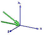
In the following figure the animation of a CutForceAndTorque sensor is shown. The dark blue coordinate system is frame_b, and the green arrows are the cut force and the cut torque, respectively, acting at frame_b and with negative sign at frame_a.
Extends from Modelica.Mechanics.MultiBody.Sensors.Internal.PartialCutForceSensor (Base model to measure the cut force and/or torque between two frames, defined by components).
| Type | Name | Default | Description |
|---|---|---|---|
| Boolean | animation | true | = true, if animation shall be enabled (show force and torque arrow) |
| Boolean | positiveSign | true | = true, if force and torque with positive sign is returned (= frame_a.f/.t), otherwise with negative sign (= frame_b.f/.t) |
| ResolveInFrameA | resolveInFrame | Modelica.Mechanics.MultiBody... | Frame in which output vector(s) is/are resolved (1: world, 2: frame_a, 3: frame_resolve) |
| if animation = true | |||
| Real | N_to_m | 1000 | Force arrow scaling (length = force/N_to_m) [N/m] |
| Real | Nm_to_m | 1000 | Torque arrow scaling (length = torque/Nm_to_m) [N.m/m] |
| Diameter | forceDiameter | world.defaultArrowDiameter | Diameter of force arrow [m] |
| Diameter | torqueDiameter | forceDiameter | Diameter of torque arrow [m] |
| Color | forceColor | Modelica.Mechanics.MultiBody... | Color of force arrow |
| Color | torqueColor | Modelica.Mechanics.MultiBody... | Color of torque arrow |
| SpecularCoefficient | specularCoefficient | world.defaultSpecularCoeffic... | Reflection of ambient light (= 0: light is completely absorbed) |
| Type | Name | Description |
|---|---|---|
| output RealOutput | force[3] | Cut force resolved in frame defined by resolveInFrame [N] |
| output RealOutput | torque[3] | Cut torque resolved in frame defined by resolveInFrame |
| Frame_a | frame_a | Coordinate system a |
| Frame_b | frame_b | Coordinate system b |
| Frame_resolve | frame_resolve | Output vectors are optionally resolved in this frame (cut-force/-torque are set to zero) |
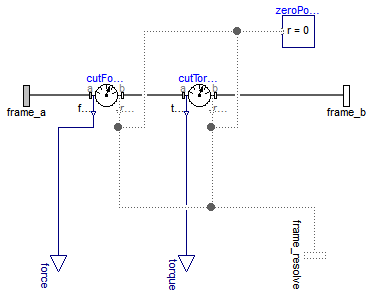
model CutForceAndTorque "Measure cut force and cut torque vector" import SI = Modelica.SIunits; import Modelica.Mechanics.MultiBody.Types;Modelica.Blocks.Interfaces.RealOutput force[3](final quantity="Force", final unit="N") "Cut force resolved in frame defined by resolveInFrame"; Modelica.Blocks.Interfaces.RealOutput torque[3] "Cut torque resolved in frame defined by resolveInFrame"; parameter Boolean animation=true "= true, if animation shall be enabled (show force and torque arrow)"; parameter Boolean positiveSign=true "= true, if force and torque with positive sign is returned (= frame_a.f/.t), otherwise with negative sign (= frame_b.f/.t)"; input Real N_to_m(unit="N/m") = 1000 "Force arrow scaling (length = force/N_to_m)"; input Real Nm_to_m(unit="N.m/m") = 1000 "Torque arrow scaling (length = torque/Nm_to_m)"; input SI.Diameter forceDiameter=world.defaultArrowDiameter "Diameter of force arrow"; input SI.Diameter torqueDiameter=forceDiameter " Diameter of torque arrow"; input Types.Color forceColor=Modelica.Mechanics.MultiBody.Types.Defaults.ForceColor "Color of force arrow"; input Types.Color torqueColor=Modelica.Mechanics.MultiBody.Types.Defaults.TorqueColor "Color of torque arrow"; input Types.SpecularCoefficient specularCoefficient = world.defaultSpecularCoefficient "Reflection of ambient light (= 0: light is completely absorbed)"; extends Modelica.Mechanics.MultiBody.Sensors.Internal.PartialCutForceSensor; protected parameter Integer csign=if positiveSign then +1 else -1; SI.Position f_in_m[3]=frame_a.f*csign/N_to_m "Force mapped from N to m for animation"; SI.Position t_in_m[3]=frame_a.t*csign/Nm_to_m "Torque mapped from Nm to m for animation"; Visualizers.Advanced.Arrow forceArrow( diameter=forceDiameter, color=forceColor, specularCoefficient=specularCoefficient, R=frame_b.R, r=frame_b.r_0, r_tail=f_in_m, r_head=-f_in_m) if world.enableAnimation and animation; Visualizers.Advanced.DoubleArrow torqueArrow( diameter=torqueDiameter, color=torqueColor, specularCoefficient=specularCoefficient, R=frame_b.R, r=frame_b.r_0, r_tail=t_in_m, r_head=-t_in_m) if world.enableAnimation and animation;Internal.BasicCutForce cutForce(resolveInFrame=resolveInFrame, positiveSign= positiveSign); Internal.BasicCutTorque cutTorque(resolveInFrame=resolveInFrame, positiveSign= positiveSign); Modelica.Mechanics.MultiBody.Interfaces.ZeroPosition zeroPosition if not (resolveInFrame == Modelica.Mechanics.MultiBody.Types.ResolveInFrameA.frame_resolve); equationconnect(cutForce.frame_a, frame_a); connect(cutForce.frame_b, cutTorque.frame_a); connect(cutTorque.frame_b, frame_b); connect(cutForce.force, force); connect(cutTorque.torque, torque); connect(zeroPosition.frame_resolve, cutTorque.frame_resolve); connect(zeroPosition.frame_resolve, cutForce.frame_resolve); connect(cutForce.frame_resolve, frame_resolve); connect(cutTorque.frame_resolve, frame_resolve); end CutForceAndTorque;
 Modelica.Mechanics.MultiBody.Sensors.Power
This component provides the power flowing from frame_a to frame_b as output signal power.
Extends from Modelica.Icons.RotationalSensor (Icon representing a round measurement device), Modelica.Mechanics.MultiBody.Interfaces.PartialTwoFrames (Base model for components providing two frame connectors + outer world + assert to guarantee that the component is connected).
| Type | Name | Description |
|---|---|---|
| Frame_a | frame_a | Coordinate system fixed to the component with one cut-force and cut-torque |
| Frame_b | frame_b | Coordinate system fixed to the component with one cut-force and cut-torque |
| output RealOutput | power | Power at frame_a as output signal [W] |
model Power "Measure power flowing from frame_a to frame_b" import SI = Modelica.SIunits; extends Modelica.Icons.RotationalSensor; extends Modelica.Mechanics.MultiBody.Interfaces.PartialTwoFrames;Modelica.Blocks.Interfaces.RealOutput power(quantity="Power",unit="W") "Power at frame_a as output signal"; equation Connections.branch(frame_a.R, frame_b.R); frame_a.r_0 = frame_b.r_0; frame_a.R = frame_b.R; zeros(3) = frame_a.f + frame_b.f; zeros(3) = frame_a.t + frame_b.t; power = frame_a.f*Frames.resolve2(frame_a.R, der(frame_a.r_0)) + frame_a.t*Frames.angularVelocity2(frame_a.R);end Power;
 Modelica.Mechanics.MultiBody.Sensors.TansformAbsoluteVector
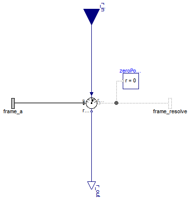
The input vector "Real r_in[3]" is assumed to be an absolute kinematic quantity of frame_a that is defined to be resolved in the frame defined with parameter "frame_r_in". This model resolves vector r_in in the coordinate system defined with parameter "frame_r_out" and returns the transformed output vector as "Real r_out[3]";
Extends from Modelica.Icons.RotationalSensor (Icon representing a round measurement device).
| Type | Name | Default | Description |
|---|---|---|---|
| ResolveInFrameA | frame_r_in | Modelica.Mechanics.MultiBody... | Frame in which vector r_in is resolved (1: world, 2: frame_a, 3: frame_resolve) |
| ResolveInFrameA | frame_r_out | frame_r_in | Frame in which vector r_in shall be resolved and provided as r_out (1: world, 2: frame_a, 3: frame_resolve) |
| Type | Name | Description |
|---|---|---|
| Frame_a | frame_a | Coordinate system from which absolute kinematic quantities are measured |
| Frame_resolve | frame_resolve | Coordinate system in which r_in or r_out is optionally resolved |
| input RealInput | r_in[3] | Input vector resolved in frame defined by frame_r_in |
| output RealOutput | r_out[3] | Input vector r_in resolved in frame defined by frame_r_out |
model TansformAbsoluteVector "Transform absolute vector in to another frame" extends Modelica.Icons.RotationalSensor;Modelica.Mechanics.MultiBody.Interfaces.Frame_a frame_a "Coordinate system from which absolute kinematic quantities are measured"; Modelica.Mechanics.MultiBody.Interfaces.Frame_resolve frame_resolve if (frame_r_in == Modelica.Mechanics.MultiBody.Types.ResolveInFrameA.frame_resolve) or (frame_r_out == Modelica.Mechanics.MultiBody.Types.ResolveInFrameA.frame_resolve) "Coordinate system in which r_in or r_out is optionally resolved"; Blocks.Interfaces.RealInput r_in[3] "Input vector resolved in frame defined by frame_r_in"; Blocks.Interfaces.RealOutput r_out[3] "Input vector r_in resolved in frame defined by frame_r_out"; parameter Modelica.Mechanics.MultiBody.Types.ResolveInFrameA frame_r_in= Modelica.Mechanics.MultiBody.Types.ResolveInFrameA.frame_a "Frame in which vector r_in is resolved (1: world, 2: frame_a, 3: frame_resolve)"; parameter Modelica.Mechanics.MultiBody.Types.ResolveInFrameA frame_r_out= frame_r_in "Frame in which vector r_in shall be resolved and provided as r_out (1: world, 2: frame_a, 3: frame_resolve)";protected Internal.BasicTransformAbsoluteVector basicTransformVector(frame_r_in= frame_r_in, frame_r_out=frame_r_out); Modelica.Mechanics.MultiBody.Interfaces.ZeroPosition zeroPosition if not (frame_r_in == Modelica.Mechanics.MultiBody.Types.ResolveInFrameA.frame_resolve or frame_r_out == Modelica.Mechanics.MultiBody.Types.ResolveInFrameA.frame_resolve); equationconnect(basicTransformVector.frame_a, frame_a); connect(basicTransformVector.frame_resolve, frame_resolve); connect(zeroPosition.frame_resolve, basicTransformVector.frame_resolve); connect(basicTransformVector.r_out, r_out); connect(basicTransformVector.r_in, r_in); end TansformAbsoluteVector;
 Modelica.Mechanics.MultiBody.Sensors.TansformRelativeVector
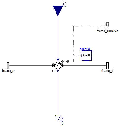
The input vector "Real r_in[3]" is assumed to be a relative kinematic quantity between frame_a and frame_b that is defined to be resolved in the frame defined with parameter "frame_r_in". This model resolves vector r_in in the coordinate system defined with parameter "frame_r_out" and returns the transformed output vector as "Real r_out[3]";
Extends from Internal.PartialRelativeSensor (Partial relative sensor model for sensors defined by components).
| Type | Name | Default | Description |
|---|---|---|---|
| ResolveInFrameAB | frame_r_in | Modelica.Mechanics.MultiBody... | Frame in which vector r_in is resolved (1: world, 2: frame_a, 3: frame_b, 4: frame_resolve) |
| ResolveInFrameAB | frame_r_out | frame_r_in | Frame in which vector r_in shall be resolved and provided as r_out (1: world, 2: frame_a, 3: frame_b, 4: frame_resolve) |
| Type | Name | Description |
|---|---|---|
| Frame_a | frame_a | Coordinate system a |
| Frame_b | frame_b | Coordinate system b |
| Frame_resolve | frame_resolve | Coordinate system in which r_in or r_out is optionally resolved |
| input RealInput | r_in[3] | Input vector resolved in frame defined by frame_r_in |
| output RealOutput | r_out[3] | Input vector r_in resolved in frame defined by frame_r_out |
model TansformRelativeVector "Transform relative vector in to another frame" extends Internal.PartialRelativeSensor;Modelica.Mechanics.MultiBody.Interfaces.Frame_resolve frame_resolve if (frame_r_in == Modelica.Mechanics.MultiBody.Types.ResolveInFrameAB.frame_resolve) or (frame_r_out == Modelica.Mechanics.MultiBody.Types.ResolveInFrameAB.frame_resolve) "Coordinate system in which r_in or r_out is optionally resolved"; Blocks.Interfaces.RealInput r_in[3] "Input vector resolved in frame defined by frame_r_in"; Blocks.Interfaces.RealOutput r_out[3] "Input vector r_in resolved in frame defined by frame_r_out"; parameter Modelica.Mechanics.MultiBody.Types.ResolveInFrameAB frame_r_in= Modelica.Mechanics.MultiBody.Types.ResolveInFrameAB.frame_a "Frame in which vector r_in is resolved (1: world, 2: frame_a, 3: frame_b, 4: frame_resolve)"; parameter Modelica.Mechanics.MultiBody.Types.ResolveInFrameAB frame_r_out= frame_r_in "Frame in which vector r_in shall be resolved and provided as r_out (1: world, 2: frame_a, 3: frame_b, 4: frame_resolve)";protected Modelica.Mechanics.MultiBody.Sensors.Internal.BasicTransformRelativeVector basicTransformVector( frame_r_in=frame_r_in, frame_r_out=frame_r_out); Modelica.Mechanics.MultiBody.Interfaces.ZeroPosition zeroPosition if not (frame_r_in == Modelica.Mechanics.MultiBody.Types.ResolveInFrameAB.frame_resolve or frame_r_out == Modelica.Mechanics.MultiBody.Types.ResolveInFrameAB.frame_resolve); equationconnect(basicTransformVector.frame_a, frame_a); connect(basicTransformVector.frame_b, frame_b); connect(basicTransformVector.frame_resolve, frame_resolve); connect(zeroPosition.frame_resolve, basicTransformVector.frame_resolve); connect(basicTransformVector.r_out, r_out); connect(basicTransformVector.r_in, r_in); end TansformRelativeVector;