


This package contains components that exert forces and torques between two frame connectors, e.g., between two parts.
| Model | Description |
|---|---|
| WorldForce | External force acting at the frame to which this component
is connected and defined by 3 input signals,
that are interpreted as one vector resolved in frame world, frame_b or frame_resolve. |
| WorldTorque | External torque acting at the frame to which this component
is connected and defined by 3 input signals,
that are interpreted as one vector resolved in frame world, frame_b or frame_resolve. |
| WorldForceAndTorque | External force and external torque acting at the frame
to which this component
is connected and defined by 3+3 input signals,
that are interpreted as a force and as a torque vector
resolved in frame world, frame_b or frame_resolve.
|
| Force | Force acting between two frames defined by 3 input signals
resolved in frame world, frame_a, frame_b or in frame_resolve. |
| Torque | Torque acting between two frames defined by 3 input signals
resolved in frame world, frame_a, frame_b or in frame_resolve. |
| ForceAndTorque | Force and torque acting between two frames defined by 3+3 input signals
resolved in frame world, frame_a, frame_b or in frame_resolve. |
| LineForceWithMass | General line force component with an optional point mass
on the connection line. The force law can be defined by a
component of Modelica.Mechanics.Translational |
| LineForceWithTwoMasses | General line force component with two optional point masses
on the connection line. The force law can be defined by a
component of Modelica.Mechanics.Translational |
| Spring | Linear translational spring with optional mass |
| Damper | Linear (velocity dependent) damper |
| SpringDamperParallel | Linear spring and damper in parallel connection |
| SpringDamperSeries | Linear spring and damper in series connection |
Extends from Modelica.Icons.SourcesPackage (Icon for packages containing sources).
| Name | Description |
|---|---|
| External force acting at frame_b, defined by 3 input signals and resolved in frame world, frame_b or frame_resolve | |
| External torque acting at frame_b, defined by 3 input signals and resolved in frame world, frame_b or frame_resolve | |
| External force and torque acting at frame_b, defined by 3+3 input signals and resolved in frame world, frame_b or in frame_resolve | |
| Force acting between two frames, defined by 3 input signals and resolved in frame world, frame_a, frame_b or frame_resolve | |
| Torque acting between two frames, defined by 3 input signals and resolved in frame world, frame_a, frame_b or frame_resolve | |
| Force and torque acting between two frames, defined by 3+3 input signals and resolved in frame world, frame_a, frame_b or frame_resolve | |
| General line force component with an optional point mass on the connection line | |
| General line force component with two optional point masses on the connection line | |
| Linear translational spring with optional mass | |
| Linear (velocity dependent) damper | |
| Linear spring and linear damper in parallel | |
| Linear spring and linear damper in series connection | |
| Internal package, should not be used by user |
 Modelica.Mechanics.MultiBody.Forces.WorldForce
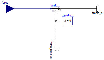
The 3 signals of the force connector are interpreted as the x-, y- and z-coordinates of a force acting at the frame connector to which frame_b of this component is attached. Via parameter resolveInFrame it is defined, in which frame these coordinates shall be resolved:
| Types.ResolveInFrameB. | Meaning |
|---|---|
| world | Resolve input force in world frame (= default) |
| frame_b | Resolve input force in frame_b |
| frame_resolve | Resolve input force in frame_resolve (frame_resolve must be connected) |
If resolveInFrame = Types.ResolveInFrameB.frame_resolve, the force coordinates are with respect to the frame, that is connected to frame_resolve.
If force={100,0,0}, and for all parameters the default setting is used, then the interpretation is that a force of 100 N is acting along the positive x-axis of frame_b.
Note, the cut-torque in frame_b (frame_b.t) is always set to zero. Conceptually, a force and torque acts on the world frame in such a way that the force and torque balance between world.frame_b and frame_b is fulfilled. For efficiency reasons, this reaction torque is, however, not computed.
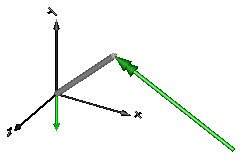
This force component is by default visualized as an arrow acting at the connector to which it is connected. The diameter and color of the arrow can be defined via variables diameter and color. The arrow points in the direction defined by the force signal. The length of the arrow is proportional to the length of the force vector using parameter N_to_m as scaling factor. For example, if N_to_m = 100 N/m, then a force of 350 N is displayed as an arrow of length 3.5 m.
An example how to use this model is given in the following figure:
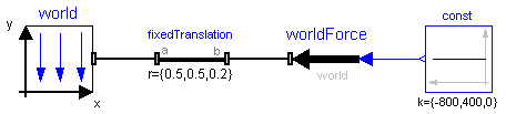
This leads to the following animation

Extends from Interfaces.PartialOneFrame_b (Base model for components providing one frame_b connector + outer world + assert to guarantee that the component is connected).
| Type | Name | Default | Description |
|---|---|---|---|
| Boolean | animation | true | = true, if animation shall be enabled |
| ResolveInFrameB | resolveInFrame | Modelica.Mechanics.MultiBody... | Frame in which input force is resolved (1: world, 2: frame_b, 3: frame_resolve) |
| if animation = true | |||
| Real | N_to_m | world.defaultN_to_m | Force arrow scaling (length = force/N_to_m) [N/m] |
| Diameter | diameter | world.defaultArrowDiameter | Diameter of force arrow [m] |
| Color | color | Modelica.Mechanics.MultiBody... | Color of arrow |
| SpecularCoefficient | specularCoefficient | world.defaultSpecularCoeffic... | Reflection of ambient light (= 0: light is completely absorbed) |
| Type | Name | Description |
|---|---|---|
| Frame_b | frame_b | Coordinate system fixed to the component with one cut-force and cut-torque |
| Frame_resolve | frame_resolve | The input signals are optionally resolved in this frame |
| input RealInput | force[3] | x-, y-, z-coordinates of force resolved in frame defined by resolveInFrame [N] |
model WorldForce "External force acting at frame_b, defined by 3 input signals and resolved in frame world, frame_b or frame_resolve" import SI = Modelica.SIunits; extends Interfaces.PartialOneFrame_b;Interfaces.Frame_resolve frame_resolve if resolveInFrame == Modelica.Mechanics.MultiBody.Types.ResolveInFrameB.frame_resolve "The input signals are optionally resolved in this frame"; Modelica.Blocks.Interfaces.RealInput force[3](each final quantity="Force", each final unit= "N") "x-, y-, z-coordinates of force resolved in frame defined by resolveInFrame"; parameter Boolean animation=true "= true, if animation shall be enabled"; parameter Modelica.Mechanics.MultiBody.Types.ResolveInFrameB resolveInFrame= Modelica.Mechanics.MultiBody.Types.ResolveInFrameB.world "Frame in which input force is resolved (1: world, 2: frame_b, 3: frame_resolve)"; parameter Real N_to_m(unit="N/m") = world.defaultN_to_m "Force arrow scaling (length = force/N_to_m)"; input SI.Diameter diameter=world.defaultArrowDiameter "Diameter of force arrow"; input Types.Color color=Modelica.Mechanics.MultiBody.Types.Defaults.ForceColor "Color of arrow"; input Types.SpecularCoefficient specularCoefficient = world.defaultSpecularCoefficient "Reflection of ambient light (= 0: light is completely absorbed)"; protected SI.Position f_in_m[3]=frame_b.f/N_to_m "Force mapped from N to m for animation"; Visualizers.Advanced.Arrow arrow( diameter=diameter, color=color, specularCoefficient=specularCoefficient, R=frame_b.R, r=frame_b.r_0, r_tail=f_in_m, r_head=-f_in_m) if world.enableAnimation and animation;public Internal.BasicWorldForce basicWorldForce(resolveInFrame=resolveInFrame); protected Interfaces.ZeroPosition zeroPosition if not (resolveInFrame == Modelica.Mechanics.MultiBody.Types.ResolveInFrameB.frame_resolve); equationconnect(basicWorldForce.frame_b, frame_b); connect(basicWorldForce.force, force); connect(basicWorldForce.frame_resolve, frame_resolve); connect(zeroPosition.frame_resolve, basicWorldForce.frame_resolve); end WorldForce;
 Modelica.Mechanics.MultiBody.Forces.WorldTorque
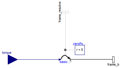
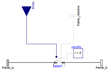
The 3 signals of the torque connector are interpreted as the x-, y- and z-coordinates of a torque acting at the frame connector to which frame_b of this component is attached. Via parameter resolveInFrame it is defined, in which frame these coordinates shall be resolved:
| Types.ResolveInFrameB. | Meaning |
|---|---|
| world | Resolve input torque in world frame (= default) |
| frame_b | Resolve input torque in frame_b |
| frame_resolve | Resolve input torque in frame_resolve (frame_resolve must be connected) |
If resolveInFrame = Types.ResolveInFrameB.frame_resolve, the torque coordinates are with respect to the frame, that is connected to frame_resolve.
If torque={100,0,0}, and for all parameters the default setting is used, then the interpretation is that a torque of 100 N is acting along the positive x-axis of frame_b.
Note, the cut-force in frame_b (frame_b.f) is always set to zero. Conceptually, a force and torque acts on the world frame in such a way that the force and torque balance between world.frame_b and frame_b is fulfilled. For efficiency reasons, this reaction torque is, however, not computed.
This torque component is by default visualized as a double arrow acting at the connector to which it is connected. The diameter and color of the arrow can be defined via variables diameter and color. The double arrow points in the direction defined by the torque vector. The length of the double arrow is proportional to the length of the torque vector using parameter Nm_to_m as scaling factor. For example, if Nm_to_m = 100 Nm/m, then a torque of 350 Nm is displayed as an arrow of length 3.5 m.
An example how to use this model is given in the following figure:
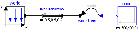
This leads to the following animation
Extends from Interfaces.PartialOneFrame_b (Base model for components providing one frame_b connector + outer world + assert to guarantee that the component is connected).
| Type | Name | Default | Description |
|---|---|---|---|
| Boolean | animation | true | = true, if animation shall be enabled |
| ResolveInFrameB | resolveInFrame | Modelica.Mechanics.MultiBody... | Frame in which input torque is resolved (1: world, 2: frame_b, 3: frame_resolve) |
| if animation = true | |||
| Real | Nm_to_m | world.defaultNm_to_m | Torque arrow scaling (length = torque/Nm_to_m) [N.m/m] |
| Diameter | diameter | world.defaultArrowDiameter | Diameter of torque arrow [m] |
| Color | color | Modelica.Mechanics.MultiBody... | Color of arrow |
| SpecularCoefficient | specularCoefficient | world.defaultSpecularCoeffic... | Reflection of ambient light (= 0: light is completely absorbed) |
| Type | Name | Description |
|---|---|---|
| Frame_b | frame_b | Coordinate system fixed to the component with one cut-force and cut-torque |
| Frame_resolve | frame_resolve | The input signals are optionally resolved in this frame |
| input RealInput | torque[3] | x-, y-, z-coordiantes of torque resolved in frame defined by resolveInFrame [N.m] |
model WorldTorque "External torque acting at frame_b, defined by 3 input signals and resolved in frame world, frame_b or frame_resolve" extends Interfaces.PartialOneFrame_b;Interfaces.Frame_resolve frame_resolve if resolveInFrame == Modelica.Mechanics.MultiBody.Types.ResolveInFrameB.frame_resolve "The input signals are optionally resolved in this frame"; Modelica.Blocks.Interfaces.RealInput torque[3](each final quantity="Torque", each final unit= "N.m") "x-, y-, z-coordiantes of torque resolved in frame defined by resolveInFrame"; parameter Boolean animation=true "= true, if animation shall be enabled"; parameter Modelica.Mechanics.MultiBody.Types.ResolveInFrameB resolveInFrame= Modelica.Mechanics.MultiBody.Types.ResolveInFrameB.world "Frame in which input torque is resolved (1: world, 2: frame_b, 3: frame_resolve)"; parameter Real Nm_to_m(unit="N.m/m") = world.defaultNm_to_m "Torque arrow scaling (length = torque/Nm_to_m)"; input SI.Diameter diameter=world.defaultArrowDiameter "Diameter of torque arrow"; input Types.Color color=Modelica.Mechanics.MultiBody.Types.Defaults.TorqueColor "Color of arrow"; input Types.SpecularCoefficient specularCoefficient = world.defaultSpecularCoefficient "Reflection of ambient light (= 0: light is completely absorbed)"; protected SI.Position t_in_m[3]=frame_b.t/Nm_to_m "Torque mapped from Nm to m for animation"; Visualizers.Advanced.DoubleArrow arrow( diameter=diameter, color=color, specularCoefficient=specularCoefficient, R=frame_b.R, r=frame_b.r_0, r_tail=t_in_m, r_head=-t_in_m) if world.enableAnimation and animation;public Internal.BasicWorldTorque basicWorldTorque(resolveInFrame=resolveInFrame); protected Interfaces.ZeroPosition zeroPosition if not (resolveInFrame == Modelica.Mechanics.MultiBody.Types.ResolveInFrameB.frame_resolve); equationconnect(basicWorldTorque.frame_b, frame_b); connect(basicWorldTorque.torque, torque); connect(frame_resolve, basicWorldTorque.frame_resolve); connect(zeroPosition.frame_resolve, basicWorldTorque.frame_resolve); end WorldTorque;
 Modelica.Mechanics.MultiBody.Forces.WorldForceAndTorque
The 3 signals of the force and torque connector are interpreted as the x-, y- and z-coordinates of a force and torque acting at the frame connector to which frame_b of this component is attached. Via parameter resolveInFrame it is defined, in which frame these coordinates shall be resolved:
| Types.ResolveInFrameB. | Meaning |
|---|---|
| world | Resolve input forceand torque in world frame (= default) |
| frame_b | Resolve input force and torque in frame_b |
| frame_resolve | Resolve input force and torque in frame_resolve (frame_resolve must be connected) |
If resolveInFrame = Types.ResolveInFrameB.frame_resolve, the force and torque coordinates are with respect to the frame, that is connected to frame_resolve.
If force={100,0,0}, and for all parameters the default setting is used, then the interpretation is that a force of 100 N is acting along the positive x-axis of frame_b.
Conceptually, a force and torque acts on the world frame in such a way that the force and torque balance between world.frame_b and frame_b is fulfilled. For efficiency reasons, this reaction torque is, however, not computed.
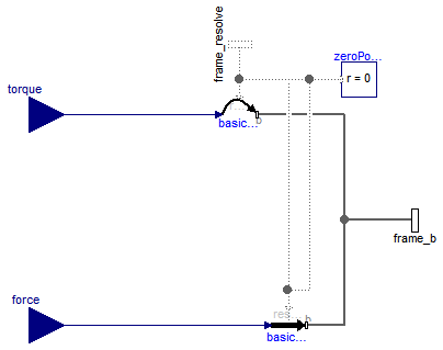
The force and torque are by default visualized as an arrow (force) and as a double arrow (torque) acting at the connector to which they are connected. The diameters and colors of the arrows can be defined via variables forceDiameter, torqueDiameter, forceColor and torqueColor. The arrows point in the directions defined by the force and torque vectors. The lengths of the arrows are proportional to the length of the force and torque vectors, respectively, using parameters N_to_m and Nm_to_m as scaling factors. For example, if N_to_m = 100 N/m, then a force of 350 N is displayed as an arrow of length 3.5 m.
An example how to use this model is given in the following figure:
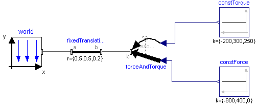
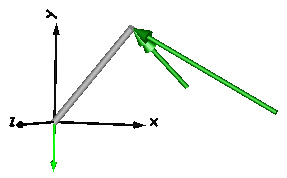
This leads to the following animation
Extends from Interfaces.PartialOneFrame_b (Base model for components providing one frame_b connector + outer world + assert to guarantee that the component is connected).
| Type | Name | Default | Description |
|---|---|---|---|
| Boolean | animation | true | = true, if animation shall be enabled |
| ResolveInFrameB | resolveInFrame | Modelica.Mechanics.MultiBody... | Frame in which input force and torque are resolved (1: world, 2: frame_b, 3: frame_resolve) |
| if animation = true | |||
| Real | N_to_m | world.defaultN_to_m | Force arrow scaling (length = force/N_to_m) [N/m] |
| Real | Nm_to_m | world.defaultNm_to_m | Torque arrow scaling (length = torque/Nm_to_m) [N.m/m] |
| Diameter | forceDiameter | world.defaultArrowDiameter | Diameter of force arrow [m] |
| Diameter | torqueDiameter | forceDiameter | Diameter of torque arrow [m] |
| Color | forceColor | Modelica.Mechanics.MultiBody... | Color of force arrow |
| Color | torqueColor | Modelica.Mechanics.MultiBody... | Color of torque arrow |
| SpecularCoefficient | specularCoefficient | world.defaultSpecularCoeffic... | Reflection of ambient light (= 0: light is completely absorbed) |
| Type | Name | Description |
|---|---|---|
| Frame_b | frame_b | Coordinate system fixed to the component with one cut-force and cut-torque |
| Frame_resolve | frame_resolve | The input signals are optionally resolved in this frame |
| input RealInput | force[3] | x-, y-, z-coordinates of force resolved in frame defined by resolveInFrame [N] |
| input RealInput | torque[3] | x-, y-, z-coordiantes of torque resolved in frame defined by resolveInFrame [N.m] |
model WorldForceAndTorque "External force and torque acting at frame_b, defined by 3+3 input signals and resolved in frame world, frame_b or in frame_resolve" import SI = Modelica.SIunits; import Modelica.Mechanics.MultiBody.Types; extends Interfaces.PartialOneFrame_b;Interfaces.Frame_resolve frame_resolve if resolveInFrame == Modelica.Mechanics.MultiBody.Types.ResolveInFrameB.frame_resolve "The input signals are optionally resolved in this frame"; Blocks.Interfaces.RealInput force[3](each final quantity="Force", each final unit= "N") "x-, y-, z-coordinates of force resolved in frame defined by resolveInFrame"; Blocks.Interfaces.RealInput torque[3](each final quantity="Torque", each final unit= "N.m") "x-, y-, z-coordiantes of torque resolved in frame defined by resolveInFrame"; parameter Boolean animation=true "= true, if animation shall be enabled"; parameter Modelica.Mechanics.MultiBody.Types.ResolveInFrameB resolveInFrame= Modelica.Mechanics.MultiBody.Types.ResolveInFrameB.world "Frame in which input force and torque are resolved (1: world, 2: frame_b, 3: frame_resolve)"; parameter Real N_to_m(unit="N/m") = world.defaultN_to_m " Force arrow scaling (length = force/N_to_m)"; parameter Real Nm_to_m(unit="N.m/m") = world.defaultNm_to_m " Torque arrow scaling (length = torque/Nm_to_m)"; input SI.Diameter forceDiameter=world.defaultArrowDiameter " Diameter of force arrow"; input SI.Diameter torqueDiameter=forceDiameter " Diameter of torque arrow"; input Types.Color forceColor=Modelica.Mechanics.MultiBody.Types.Defaults.ForceColor " Color of force arrow"; input Types.Color torqueColor=Modelica.Mechanics.MultiBody.Types.Defaults.TorqueColor " Color of torque arrow"; input Types.SpecularCoefficient specularCoefficient = world.defaultSpecularCoefficient "Reflection of ambient light (= 0: light is completely absorbed)"; protected SI.Position f_in_m[3]=frame_b.f/N_to_m "Force mapped from N to m for animation"; SI.Position t_in_m[3]=frame_b.t/Nm_to_m "Torque mapped from Nm to m for animation"; Visualizers.Advanced.Arrow forceArrow( diameter=forceDiameter, color=forceColor, specularCoefficient=specularCoefficient, R=frame_b.R, r=frame_b.r_0, r_tail=f_in_m, r_head=-f_in_m) if world.enableAnimation and animation; Visualizers.Advanced.DoubleArrow torqueArrow( diameter=torqueDiameter, color=torqueColor, specularCoefficient=specularCoefficient, R=frame_b.R, r=frame_b.r_0, r_tail=t_in_m, r_head=-t_in_m) if world.enableAnimation and animation;public Internal.BasicWorldForce basicWorldForce(resolveInFrame=resolveInFrame); Internal.BasicWorldTorque basicWorldTorque(resolveInFrame=resolveInFrame); protected Interfaces.ZeroPosition zeroPosition if not (resolveInFrame == Modelica.Mechanics.MultiBody.Types.ResolveInFrameB.frame_resolve); equationconnect(basicWorldForce.frame_b, frame_b); connect(basicWorldForce.force, force); connect(basicWorldTorque.frame_b, frame_b); connect(basicWorldTorque.torque, torque); connect(basicWorldForce.frame_resolve, frame_resolve); connect(basicWorldTorque.frame_resolve, frame_resolve); connect(zeroPosition.frame_resolve, basicWorldTorque.frame_resolve); connect(zeroPosition.frame_resolve, basicWorldForce.frame_resolve); end WorldForceAndTorque;
 Modelica.Mechanics.MultiBody.Forces.Force
The 3 signals of the force connector are interpreted as the x-, y- and z-coordinates of a force acting at the frame connector to which frame_b of this component is attached. Via parameter resolveInFrame it is defined, in which frame these coordinates shall be resolved:
| Types.ResolveInFrameAB. | Meaning |
|---|---|
| world | Resolve input force in world frame |
| frame_a | Resolve input force in frame_a |
| frame_b | Resolve input force in frame_b (= default) |
| frame_resolve | Resolve input force in frame_resolve (frame_resolve must be connected) |
If resolveInFrame = ResolveInFrameAB.frame_resolve, the force coordinates are with respect to the frame, that is connected to frame_resolve.
If force={100,0,0}, and for all parameters the default setting is used, then the interpretation is that a force of 100 N is acting along the positive x-axis of frame_b.
Note, the cut-torque in frame_b (frame_b.t) is always set to zero. Additionally, a force and torque acts on frame_a in such a way that the force and torque balance between frame_a and frame_b is fulfilled.
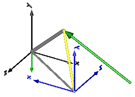
An example how to use this model is given in the following figure:
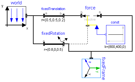
This leads to the following animation (the yellow cylinder characterizes the line between frame_a and frame_b of the Force component, i.e., the force acts with negative sign also on the opposite side of this cylinder, but for clarity this is not shown in the animation):
Extends from Modelica.Mechanics.MultiBody.Interfaces.PartialTwoFrames (Base model for components providing two frame connectors + outer world + assert to guarantee that the component is connected).
| Type | Name | Default | Description |
|---|---|---|---|
| Boolean | animation | true | = true, if animation shall be enabled |
| ResolveInFrameAB | resolveInFrame | Modelica.Mechanics.MultiBody... | Frame in which input force is resolved (1: world, 2: frame_a, 3: frame_b, 4: frame_resolve) |
| if animation = true | |||
| Real | N_to_m | world.defaultN_to_m | Force arrow scaling (length = force/N_to_m) [N/m] |
| Diameter | forceDiameter | world.defaultArrowDiameter | Diameter of force arrow [m] |
| Diameter | connectionLineDiameter | forceDiameter | Diameter of line connecting frame_a and frame_b [m] |
| Color | forceColor | Modelica.Mechanics.MultiBody... | Color of force arrow |
| Color | connectionLineColor | Modelica.Mechanics.MultiBody... | Color of line connecting frame_a and frame_b |
| SpecularCoefficient | specularCoefficient | world.defaultSpecularCoeffic... | Reflection of ambient light (= 0: light is completely absorbed) |
| Type | Name | Description |
|---|---|---|
| Frame_a | frame_a | Coordinate system fixed to the component with one cut-force and cut-torque |
| Frame_b | frame_b | Coordinate system fixed to the component with one cut-force and cut-torque |
| Frame_resolve | frame_resolve | The input signals are optionally resolved in this frame |
| input RealInput | force[3] | x-, y-, z-coordinates of force resolved in frame defined by resolveInFrame [N] |
model Force "Force acting between two frames, defined by 3 input signals and resolved in frame world, frame_a, frame_b or frame_resolve" import SI = Modelica.SIunits; extends Modelica.Mechanics.MultiBody.Interfaces.PartialTwoFrames;Interfaces.Frame_resolve frame_resolve if resolveInFrame == Modelica.Mechanics.MultiBody.Types.ResolveInFrameAB.frame_resolve "The input signals are optionally resolved in this frame"; Modelica.Blocks.Interfaces.RealInput force[3](each final quantity="Force", each final unit= "N") "x-, y-, z-coordinates of force resolved in frame defined by resolveInFrame"; parameter Boolean animation=true "= true, if animation shall be enabled"; parameter Modelica.Mechanics.MultiBody.Types.ResolveInFrameAB resolveInFrame= Modelica.Mechanics.MultiBody.Types.ResolveInFrameAB.frame_b "Frame in which input force is resolved (1: world, 2: frame_a, 3: frame_b, 4: frame_resolve)"; parameter Real N_to_m(unit="N/m") = world.defaultN_to_m " Force arrow scaling (length = force/N_to_m)"; input SI.Diameter forceDiameter=world.defaultArrowDiameter " Diameter of force arrow"; input SI.Diameter connectionLineDiameter=forceDiameter " Diameter of line connecting frame_a and frame_b"; input Types.Color forceColor=Modelica.Mechanics.MultiBody.Types.Defaults.ForceColor " Color of force arrow"; input Types.Color connectionLineColor=Modelica.Mechanics.MultiBody.Types.Defaults.SensorColor " Color of line connecting frame_a and frame_b"; input Types.SpecularCoefficient specularCoefficient = world.defaultSpecularCoefficient "Reflection of ambient light (= 0: light is completely absorbed)"; protected SI.Position f_in_m[3]=frame_b.f/N_to_m "Force mapped from N to m for animation"; Visualizers.Advanced.Arrow forceArrow( diameter=forceDiameter, color=forceColor, specularCoefficient=specularCoefficient, R=frame_b.R, r=frame_b.r_0, r_tail=f_in_m, r_head=-f_in_m) if world.enableAnimation and animation; Visualizers.Advanced.Shape connectionLine( shapeType="cylinder", lengthDirection=basicForce.r_0, widthDirection={0,1,0}, length=Modelica.Math.Vectors.length(basicForce.r_0), width=connectionLineDiameter, height=connectionLineDiameter, color=connectionLineColor, specularCoefficient=specularCoefficient, r=frame_a.r_0) if world.enableAnimation and animation;public MultiBody.Forces.Internal.BasicForce basicForce(resolveInFrame=resolveInFrame); protected MultiBody.Interfaces.ZeroPosition zeroPosition if not (resolveInFrame == Modelica.Mechanics.MultiBody.Types.ResolveInFrameAB.frame_resolve); equationconnect(basicForce.frame_a, frame_a); connect(basicForce.frame_b, frame_b); connect(force, basicForce.force); connect(basicForce.frame_resolve, frame_resolve); connect(zeroPosition.frame_resolve, basicForce.frame_resolve); end Force;
 Modelica.Mechanics.MultiBody.Forces.Torque
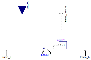
The 3 signals of the torque connector are interpreted as the x-, y- and z-coordinates of a torque acting at the frame connector to which frame_b of this component is attached. Via parameter resolveInFrame it is defined, in which frame these coordinates shall be resolved:
| Types.ResolveInFrameAB. | Meaning |
|---|---|
| world | Resolve input torque in world frame |
| frame_a | Resolve input torque in frame_a |
| frame_b | Resolve input torque in frame_b (= default) |
| frame_resolve | Resolve input torque in frame_resolve (frame_resolve must be connected) |
If resolveInFrame = ResolveInFrameAB.frame_resolve, the torque coordinates are with respect to the frame, that is connected to frame_resolve.
If torque={100,0,0}, and for all parameters the default setting is used, then the interpretation is that a torque of 100 N.m is acting along the positive x-axis of frame_b.
Note, the cut-forces in frame_a and frame_b (frame_a.f, frame_b.f) are always set to zero and the cut-torque at frame_a (frame_a.t) is the same as the cut-torque at frame_b (frame_b.t) but with opposite sign.
An example how to use this model is given in the following figure:
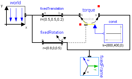
This leads to the following animation (the yellow cylinder characterizes the line between frame_a and frame_b of the Torque component, i.e., the torque acts with negative sign also on the opposite side of this cylinder, but for clarity this is not shown in the animation):

Extends from Modelica.Mechanics.MultiBody.Interfaces.PartialTwoFrames (Base model for components providing two frame connectors + outer world + assert to guarantee that the component is connected).
| Type | Name | Default | Description |
|---|---|---|---|
| Boolean | animation | true | = true, if animation shall be enabled |
| ResolveInFrameAB | resolveInFrame | Modelica.Mechanics.MultiBody... | Frame in which input force is resolved (1: world, 2: frame_a, 3: frame_b, 4: frame_resolve) |
| if animation = true | |||
| Real | Nm_to_m | world.defaultNm_to_m | Torque arrow scaling (length = torque/Nm_to_m) [N.m/m] |
| Diameter | torqueDiameter | world.defaultArrowDiameter | Diameter of torque arrow [m] |
| Diameter | connectionLineDiameter | torqueDiameter | Diameter of line connecting frame_a and frame_b [m] |
| Color | torqueColor | Modelica.Mechanics.MultiBody... | Color of torque arrow |
| Color | connectionLineColor | Modelica.Mechanics.MultiBody... | Color of line connecting frame_a and frame_b |
| SpecularCoefficient | specularCoefficient | world.defaultSpecularCoeffic... | Reflection of ambient light (= 0: light is completely absorbed) |
| Type | Name | Description |
|---|---|---|
| Frame_a | frame_a | Coordinate system fixed to the component with one cut-force and cut-torque |
| Frame_b | frame_b | Coordinate system fixed to the component with one cut-force and cut-torque |
| Frame_resolve | frame_resolve | The input signals are optionally resolved in this frame |
| input RealInput | torque[3] | x-, y-, z-coordiantes of torque resolved in frame defined by resolveInFrame [N.m] |
model Torque "Torque acting between two frames, defined by 3 input signals and resolved in frame world, frame_a, frame_b or frame_resolve" import SI = Modelica.SIunits; extends Modelica.Mechanics.MultiBody.Interfaces.PartialTwoFrames;Interfaces.Frame_resolve frame_resolve if resolveInFrame == Modelica.Mechanics.MultiBody.Types.ResolveInFrameAB.frame_resolve "The input signals are optionally resolved in this frame"; Modelica.Blocks.Interfaces.RealInput torque[3](each final quantity="Torque", each final unit= "N.m") "x-, y-, z-coordiantes of torque resolved in frame defined by resolveInFrame"; parameter Boolean animation=true "= true, if animation shall be enabled"; parameter Modelica.Mechanics.MultiBody.Types.ResolveInFrameAB resolveInFrame= Modelica.Mechanics.MultiBody.Types.ResolveInFrameAB.frame_b "Frame in which input force is resolved (1: world, 2: frame_a, 3: frame_b, 4: frame_resolve)"; parameter Real Nm_to_m(unit="N.m/m") = world.defaultNm_to_m " Torque arrow scaling (length = torque/Nm_to_m)"; input SI.Diameter torqueDiameter=world.defaultArrowDiameter " Diameter of torque arrow"; input SI.Diameter connectionLineDiameter=torqueDiameter " Diameter of line connecting frame_a and frame_b"; input Types.Color torqueColor=Modelica.Mechanics.MultiBody.Types.Defaults.TorqueColor " Color of torque arrow"; input Types.Color connectionLineColor=Modelica.Mechanics.MultiBody.Types.Defaults.SensorColor " Color of line connecting frame_a and frame_b"; input Types.SpecularCoefficient specularCoefficient = world.defaultSpecularCoefficient "Reflection of ambient light (= 0: light is completely absorbed)"; protected SI.Position t_in_m[3]=frame_b.t/Nm_to_m "Torque mapped from Nm to m for animation"; Visualizers.Advanced.DoubleArrow torqueArrow( diameter=torqueDiameter, color=torqueColor, specularCoefficient=specularCoefficient, R=frame_b.R, r=frame_b.r_0, r_tail=t_in_m, r_head=-t_in_m) if world.enableAnimation and animation; Visualizers.Advanced.Shape connectionLine( shapeType="cylinder", lengthDirection=basicTorque.r_0, widthDirection={0,1,0}, length=Modelica.Math.Vectors.length( basicTorque.r_0), width=connectionLineDiameter, height=connectionLineDiameter, color=connectionLineColor, specularCoefficient=specularCoefficient, r=frame_a.r_0) if world.enableAnimation and animation;public Internal.BasicTorque basicTorque(resolveInFrame=resolveInFrame); protected Interfaces.ZeroPosition zeroPosition if not (resolveInFrame == Modelica.Mechanics.MultiBody.Types.ResolveInFrameAB.frame_resolve); equationconnect(basicTorque.frame_a, frame_a); connect(basicTorque.frame_b, frame_b); connect(basicTorque.torque, torque); connect(basicTorque.frame_resolve, frame_resolve); connect(zeroPosition.frame_resolve, basicTorque.frame_resolve); end Torque;
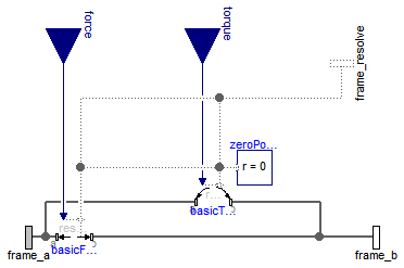
 Modelica.Mechanics.MultiBody.Forces.ForceAndTorque
| Types.ResolveInFrameAB. | Meaning |
|---|---|
| world | Resolve input force/torque in world frame |
| frame_a | Resolve input force/torque in frame_a |
| frame_b | Resolve input force/torque in frame_b (= default) |
| frame_resolve | Resolve input force/torque in frame_resolve (frame_resolve must be connected) |
If resolveInFrame = ResolveInFrameAB.frame_resolve, the force and torque coordinates are with respect to the frame, that is connected to frame_resolve.
If force={100,0,0}, and for all parameters the default setting is used, then the interpretation is that a force of 100 N is acting along the positive x-axis of frame_b.
Note, a force and torque acts on frame_a in such a way that the force and torque balance between frame_a and frame_b is fulfilled.
An example how to use this model is given in the following figure:
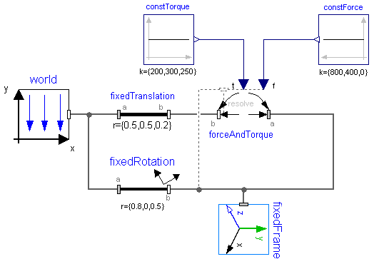
This leads to the following animation (the yellow cylinder characterizes the line between frame_a and frame_b of the ForceAndTorque component, i.e., the force and torque acts with negative sign also on the opposite side of this cylinder, but for clarity this is not shown in the animation):
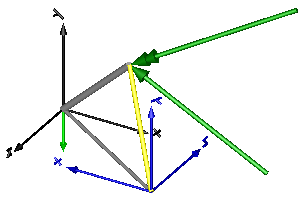
Extends from Modelica.Mechanics.MultiBody.Interfaces.PartialTwoFrames (Base model for components providing two frame connectors + outer world + assert to guarantee that the component is connected).
| Type | Name | Default | Description |
|---|---|---|---|
| Boolean | animation | true | = true, if animation shall be enabled |
| ResolveInFrameAB | resolveInFrame | Modelica.Mechanics.MultiBody... | Frame in which input force and torque are resolved (1: world, 2: frame_a, 3: frame_b, 4: frame_resolve) |
| if animation = true | |||
| Real | N_to_m | world.defaultN_to_m | Force arrow scaling (length = force/N_to_m) [N/m] |
| Real | Nm_to_m | world.defaultNm_to_m | Torque arrow scaling (length = torque/Nm_to_m) [N.m/m] |
| Diameter | forceDiameter | world.defaultArrowDiameter | Diameter of force arrow [m] |
| Diameter | torqueDiameter | forceDiameter | Diameter of torque arrow [m] |
| Diameter | connectionLineDiameter | forceDiameter | Diameter of line connecting frame_a and frame_b [m] |
| Color | forceColor | Modelica.Mechanics.MultiBody... | Color of force arrow |
| Color | torqueColor | Modelica.Mechanics.MultiBody... | Color of torque arrow |
| Color | connectionLineColor | Modelica.Mechanics.MultiBody... | Color of line connecting frame_a and frame_b |
| SpecularCoefficient | specularCoefficient | world.defaultSpecularCoeffic... | Reflection of ambient light (= 0: light is completely absorbed) |
| Type | Name | Description |
|---|---|---|
| Frame_a | frame_a | Coordinate system fixed to the component with one cut-force and cut-torque |
| Frame_b | frame_b | Coordinate system fixed to the component with one cut-force and cut-torque |
| input RealInput | force[3] | x-, y-, z-coordinates of force resolved in frame defined by resolveInFrame [N] |
| input RealInput | torque[3] | x-, y-, z-coordiantes of torque resolved in frame defined by resolveInFrame [N.m] |
| Frame_resolve | frame_resolve | The input signals are optionally resolved in this frame |
model ForceAndTorque "Force and torque acting between two frames, defined by 3+3 input signals and resolved in frame world, frame_a, frame_b or frame_resolve" import SI = Modelica.SIunits; import Modelica.Mechanics.MultiBody.Types; extends Modelica.Mechanics.MultiBody.Interfaces.PartialTwoFrames;Blocks.Interfaces.RealInput force[3](each final quantity="Force", each final unit= "N") "x-, y-, z-coordinates of force resolved in frame defined by resolveInFrame"; Blocks.Interfaces.RealInput torque[3](each final quantity="Torque", each final unit= "N.m") "x-, y-, z-coordiantes of torque resolved in frame defined by resolveInFrame"; Interfaces.Frame_resolve frame_resolve if resolveInFrame == Modelica.Mechanics.MultiBody.Types.ResolveInFrameAB.frame_resolve "The input signals are optionally resolved in this frame"; parameter Boolean animation=true "= true, if animation shall be enabled"; parameter Modelica.Mechanics.MultiBody.Types.ResolveInFrameAB resolveInFrame= Modelica.Mechanics.MultiBody.Types.ResolveInFrameAB.frame_b "Frame in which input force and torque are resolved (1: world, 2: frame_a, 3: frame_b, 4: frame_resolve)"; parameter Real N_to_m(unit="N/m") = world.defaultN_to_m "Force arrow scaling (length = force/N_to_m)"; parameter Real Nm_to_m(unit="N.m/m") = world.defaultNm_to_m "Torque arrow scaling (length = torque/Nm_to_m)"; input SI.Diameter forceDiameter=world.defaultArrowDiameter "Diameter of force arrow"; input SI.Diameter torqueDiameter=forceDiameter " Diameter of torque arrow"; input SI.Diameter connectionLineDiameter=forceDiameter "Diameter of line connecting frame_a and frame_b"; input Types.Color forceColor=Modelica.Mechanics.MultiBody.Types.Defaults.ForceColor "Color of force arrow"; input Types.Color torqueColor=Modelica.Mechanics.MultiBody.Types.Defaults.TorqueColor "Color of torque arrow"; input Types.Color connectionLineColor=Modelica.Mechanics.MultiBody.Types.Defaults.SensorColor "Color of line connecting frame_a and frame_b"; input Types.SpecularCoefficient specularCoefficient = world.defaultSpecularCoefficient "Reflection of ambient light (= 0: light is completely absorbed)"; protected SI.Position f_in_m[3]=frame_b.f/N_to_m "Force mapped from N to m for animation"; SI.Position t_in_m[3]=frame_b.t/Nm_to_m "Torque mapped from Nm to m for animation"; Visualizers.Advanced.Arrow forceArrow( diameter=forceDiameter, color=forceColor, specularCoefficient=specularCoefficient, R=frame_b.R, r=frame_b.r_0, r_tail=f_in_m, r_head=-f_in_m) if world.enableAnimation and animation; Visualizers.Advanced.DoubleArrow torqueArrow( diameter=torqueDiameter, color=torqueColor, specularCoefficient=specularCoefficient, R=frame_b.R, r=frame_b.r_0, r_tail=t_in_m, r_head=-t_in_m) if world.enableAnimation and animation; Visualizers.Advanced.Shape connectionLine( shapeType="cylinder", lengthDirection=basicForce.r_0, widthDirection={0,1,0}, length=Modelica.Math.Vectors.length( basicForce.r_0), width=connectionLineDiameter, height=connectionLineDiameter, color=connectionLineColor, specularCoefficient=specularCoefficient, r=frame_a.r_0) if world.enableAnimation and animation;public Internal.BasicForce basicForce(resolveInFrame=resolveInFrame); Internal.BasicTorque basicTorque(resolveInFrame=resolveInFrame); protected Interfaces.ZeroPosition zeroPosition if not (resolveInFrame == Modelica.Mechanics.MultiBody.Types.ResolveInFrameAB.frame_resolve); equationconnect(basicForce.frame_a, frame_a); connect(basicForce.frame_b, frame_b); connect(basicTorque.frame_b, frame_b); connect(basicTorque.frame_a, frame_a); connect(basicForce.force, force); connect(basicTorque.torque, torque); connect(basicTorque.frame_resolve, frame_resolve); connect(basicForce.frame_resolve, frame_resolve); connect(zeroPosition.frame_resolve, basicTorque.frame_resolve); connect(zeroPosition.frame_resolve, basicForce.frame_resolve); end ForceAndTorque;
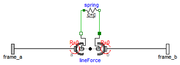
 Modelica.Mechanics.MultiBody.Forces.LineForceWithMass
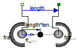
This component is used to exert a line force between the origin of frame_a and the origin of frame_b by attaching components of the 1-dimensional translational mechanical library of Modelica (Modelica.Mechanics.Translational) between the two flange connectors flange_a and flange_b. Optionally, there is a point mass on the line connecting the origin of frame_a and the origin of frame_b. This point mass approximates the mass of the force element. The distance of the point mass from frame_a as a fraction of the distance between frame_a and frame_b is defined via parameter lengthFraction (default is 0.5, i.e., the point mass is in the middle of the line).
In the translational library there is the implicit assumption that forces of components that have only one flange connector act with opposite sign on the bearings of the component. This assumption is also used in the LineForceWithMass component: If a connection is present to only one of the flange connectors, then the force in this flange connector acts implicitly with opposite sign also in the other flange connector.
Extends from Interfaces.PartialTwoFrames (Base model for components providing two frame connectors + outer world + assert to guarantee that the component is connected).
| Type | Name | Default | Description |
|---|---|---|---|
| Boolean | animateLine | true | = true, if a line shape between frame_a and frame_b shall be visualized |
| Boolean | animateMass | true | = true, if point mass shall be visualized as sphere provided m > 0 |
| Mass | m | 0 | Mass of point mass on the connetion line between the origin of frame_a and the origin of frame_b [kg] |
| Real | lengthFraction | 0.5 | Location of point mass with respect to frame_a as a fraction of the distance from frame_a to frame_b [1] |
| Animation | |||
| SpecularCoefficient | specularCoefficient | world.defaultSpecularCoeffic... | Reflection of ambient light (= 0: light is completely absorbed) |
| if animateLine = true | |||
| ShapeType | lineShapeType | "cylinder" | Type of shape visualizing the line from frame_a to frame_b |
| Length | lineShapeWidth | world.defaultArrowDiameter | Width of shape [m] |
| Length | lineShapeHeight | lineShapeWidth | Height of shape [m] |
| ShapeExtra | lineShapeExtra | 0.0 | Extra parameter for shape |
| Color | lineShapeColor | Modelica.Mechanics.MultiBody... | Color of line shape |
| if animateMass = true | |||
| Real | massDiameter | world.defaultBodyDiameter | Diameter of point mass sphere |
| Color | massColor | Modelica.Mechanics.MultiBody... | Color of point mass |
| Advanced | |||
| Position | s_small | 1.E-10 | Prevent zero-division if distance between frame_a and frame_b is zero [m] |
| If enabled, can give wrong results, see MultiBody.UsersGuide.Tutorial.ConnectionOfLineForces | |||
| Boolean | fixedRotationAtFrame_a | false | =true, if rotation frame_a.R is fixed (to directly connect line forces) |
| Boolean | fixedRotationAtFrame_b | false | =true, if rotation frame_b.R is fixed (to directly connect line forces) |
| Type | Name | Description |
|---|---|---|
| Frame_a | frame_a | Coordinate system fixed to the component with one cut-force and cut-torque |
| Frame_b | frame_b | Coordinate system fixed to the component with one cut-force and cut-torque |
| Flange_a | flange_b | 1-dim. translational flange (connect force of Translational library between flange_a and flange_b) |
| Flange_b | flange_a | 1-dim. translational flange (connect force of Translational library between flange_a and flange_b) |
model LineForceWithMass "General line force component with an optional point mass on the connection line" import SI = Modelica.SIunits; import Modelica.Mechanics.MultiBody.Types; extends Interfaces.PartialTwoFrames;Modelica.Mechanics.Translational.Interfaces.Flange_a flange_b "1-dim. translational flange (connect force of Translational library between flange_a and flange_b)"; Modelica.Mechanics.Translational.Interfaces.Flange_b flange_a "1-dim. translational flange (connect force of Translational library between flange_a and flange_b)"; parameter Boolean animateLine=true "= true, if a line shape between frame_a and frame_b shall be visualized"; parameter Boolean animateMass=true "= true, if point mass shall be visualized as sphere provided m > 0"; parameter SI.Mass m(min=0)=0 "Mass of point mass on the connetion line between the origin of frame_a and the origin of frame_b"; parameter Real lengthFraction( unit="1", min=0, max=1) = 0.5 "Location of point mass with respect to frame_a as a fraction of the distance from frame_a to frame_b"; input Types.SpecularCoefficient specularCoefficient = world.defaultSpecularCoefficient "Reflection of ambient light (= 0: light is completely absorbed)"; parameter Types.ShapeType lineShapeType="cylinder" "Type of shape visualizing the line from frame_a to frame_b"; input SI.Length lineShapeWidth=world.defaultArrowDiameter "Width of shape"; input SI.Length lineShapeHeight=lineShapeWidth "Height of shape"; parameter Types.ShapeExtra lineShapeExtra=0.0 "Extra parameter for shape"; input Types.Color lineShapeColor=Modelica.Mechanics.MultiBody.Types.Defaults.SensorColor "Color of line shape"; input Real massDiameter=world.defaultBodyDiameter "Diameter of point mass sphere"; input Types.Color massColor=Modelica.Mechanics.MultiBody.Types.Defaults.BodyColor "Color of point mass"; parameter SI.Position s_small=1.E-10 "Prevent zero-division if distance between frame_a and frame_b is zero"; parameter Boolean fixedRotationAtFrame_a=false "=true, if rotation frame_a.R is fixed (to directly connect line forces)"; parameter Boolean fixedRotationAtFrame_b=false "=true, if rotation frame_b.R is fixed (to directly connect line forces)"; SI.Distance length "Distance between the origin of frame_a and the origin of frame_b"; SI.Position r_rel_0[3] "Position vector from frame_a to frame_b resolved in world frame"; Real e_rel_0[3](each final unit="1") "Unit vector in direction from frame_a to frame_b, resolved in world frame"; protected SI.Force fa "Force from flange_a"; SI.Force fb "Force from flange_b"; SI.Position r_CM_0[3](stateSelect=StateSelect.avoid) "Position vector from world frame to point mass, resolved in world frame"; SI.Velocity v_CM_0[3](stateSelect=StateSelect.avoid) "First derivative of r_CM_0"; SI.Acceleration ag_CM_0[3] "der(v_CM_0) - gravityAcceleration"; Visualizers.Advanced.Shape lineShape( shapeType=lineShapeType, color=lineShapeColor, specularCoefficient=specularCoefficient, length=length, width=lineShapeWidth, height=lineShapeHeight, lengthDirection=e_rel_0, widthDirection=Frames.resolve1(frame_a.R, {0,1,0}), extra=lineShapeExtra, r=frame_a.r_0) if world.enableAnimation and animateLine; Visualizers.Advanced.Shape massShape( shapeType="sphere", color=massColor, specularCoefficient=specularCoefficient, length=massDiameter, width=massDiameter, height=massDiameter, lengthDirection=e_rel_0, widthDirection={0,1,0}, r_shape=e_rel_0*(length*lengthFraction - massDiameter/2), r=frame_a.r_0) if world.enableAnimation and animateMass and m > 0; equation assert(noEvent(length > s_small), " The distance between the origin of frame_a and the origin of frame_b of a LineForceWithMass component became smaller as parameter s_small (= a small number, defined in the \"Advanced\" menu). The distance is set to s_small, although it is smaller, to avoid a division by zero when computing the direction of the line force. Possible reasons for this situation: - At initial time the distance may already be zero: Change the initial positions of the bodies connected by this element. - Hardware stops are not modeled or are modeled not stiff enough. Include stops, e.g., stiff springs, or increase the stiffness if already present. - Another error in your model may lead to unrealistically large forces and torques that would in reality destroy the stops. - The flange_b connector might be defined by a pre-defined motion, e.g., with Modelica.Mechanics.Translational.Position and the predefined flange_b.s is zero or negative. "); // Determine relative position vector between the two frames r_rel_0 = frame_b.r_0 - frame_a.r_0; length = Modelica.Math.Vectors.length( r_rel_0); flange_a.s = 0; flange_b.s = length; e_rel_0 = r_rel_0/Frames.Internal.maxWithoutEvent(length, s_small); // Determine translational flange forces if cardinality(flange_a) > 0 and cardinality(flange_b) > 0 then fa = flange_a.f; fb = flange_b.f; elseif cardinality(flange_a) > 0 and cardinality(flange_b) == 0 then fa = flange_a.f; fb = -fa; elseif cardinality(flange_a) == 0 and cardinality(flange_b) > 0 then fa = -fb; fb = flange_b.f; else fa = 0; fb = 0; end if; /* Force and torque balance of point mass - Kinematics for center of mass CM of point mass including gravity r_CM_0 = frame_a.r0 + r_rel_CM_0; v_CM_0 = der(r_CM_0); ag_CM_0 = der(v_CM_0) - world.gravityAcceleration(r_CM_0); - Power balance for the connection line (f1=force on frame_a side, f2=force on frame_b side, h=lengthFraction) 0 = f1*va - m*ag_CM*(va+(vb-va)*h) + f2*vb = (f1 - m*ag_CM*(1-h))*va + (f2 - m*ag_CM*h)*vb since va and vb are completely indepedent from other the paranthesis must vanish: f1 := m*ag_CM*(1-h) f2 := m*ag_CM*h - Force balance on frame_a and frame_b finally results in 0 = frame_a.f + e_rel_a*fa - f1_a 0 = frame_b.f + e_rel_b*fb - f2_b and therefore frame_a.f = -e_rel_a*fa + m*ag_CM_a*(1-h) frame_b.f = -e_rel_b*fb + m*ag_CM_b*h */ if m > 0 then r_CM_0 = frame_a.r_0 + r_rel_0*lengthFraction; v_CM_0 = der(r_CM_0); ag_CM_0 = der(v_CM_0) - world.gravityAcceleration(r_CM_0); frame_a.f = Frames.resolve2(frame_a.R, (m*(1 - lengthFraction))*ag_CM_0 - e_rel_0*fa); frame_b.f = Frames.resolve2(frame_b.R, (m*lengthFraction)*ag_CM_0 - e_rel_0*fb); else r_CM_0 = zeros(3); v_CM_0 = zeros(3); ag_CM_0 = zeros(3); frame_a.f = -Frames.resolve2(frame_a.R, e_rel_0*fa); frame_b.f = -Frames.resolve2(frame_b.R, e_rel_0*fb); end if; // Provide appropriate equations, if direct connections of line forces if fixedRotationAtFrame_a then Connections.root(frame_a.R); frame_a.R = Frames.nullRotation(); else frame_a.t = zeros(3); end if; if fixedRotationAtFrame_b then Connections.root(frame_b.R); frame_b.R = Frames.nullRotation(); else frame_b.t = zeros(3); end if;end LineForceWithMass;
 Modelica.Mechanics.MultiBody.Forces.LineForceWithTwoMasses
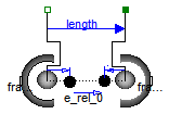
This component is used to exert a line force between the origin of frame_a and the origin of frame_b by attaching components of the 1-dimensional translational mechanical library of Modelica (Modelica.Mechanics.Translational) between the two flange connectors flange_a and flange_b. Optionally, there are two point masses on the line connecting the origin of frame_a and the origin of frame_b. These point masses approximate the masses of the force element. The locations of the two point masses are defined by their (fixed) distances of L_a relative to frame_a and of L_b relative to frame_b, respectively.
In example MultiBody.Examples.Elementary.LineForceWithTwoMasses the usage of this line force element is shown and is compared with an alternative implementation using a MultiBody.Joints.Assemblies.JointUPS component. The composition diagram of this example is displayed in the figure below.
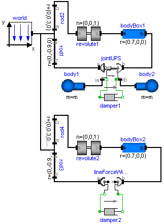
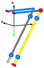
The animation view at time = 0 is shown in the next figure. The system on the left side in the front is the animation with the LineForceWithTwoMasses component whereas the system on the right side in the back is the animation with the JointUPS component. Both implementations yield the same result. However, the implementation with the LineForceWithTwoMasses component is simpler.
In the translational library there is the implicit assumption that forces of components that have only one flange connector act with opposite sign on the bearings of the component. This assumption is also used in the LineForceWithTwoMasses component: If a connection is present to only one of the flange connectors, then the force in this flange connector acts implicitly with opposite sign also in the other flange connector.
Extends from Interfaces.PartialTwoFrames (Base model for components providing two frame connectors + outer world + assert to guarantee that the component is connected).
| Type | Name | Default | Description |
|---|---|---|---|
| Boolean | animate | true | = true, if animation shall be enabled |
| Boolean | animateMasses | true | = true, if point masses shall be visualized provided animate=true and m_a, m_b > 0 |
| Mass | m_a | 0 | Mass of point mass a on the connetion line between the origin of frame_a and the origin of frame_b [kg] |
| Mass | m_b | 0 | Mass of point mass b on the connetion line between the origin of frame_a and the origin of frame_b [kg] |
| Position | L_a | 0 | Distance between point mass a and frame_a (positive, if in direction of frame_b) [m] |
| Position | L_b | L_a | Distance between point mass b and frame_b (positive, if in direction of frame_a) [m] |
| Animation | |||
| Cylinder at frame_a if animation = true | |||
| Diameter | cylinderDiameter_a | world.defaultForceWidth | Diameter of cylinder at frame_a [m] |
| Length | cylinderLength_a | 2*L_a | Length of cylinder at frame_a [m] |
| Color | color_a | {155,155,155} | Color of cylinder at frame_a |
| SpecularCoefficient | specularCoefficient | world.defaultSpecularCoeffic... | Reflection of ambient light (= 0: light is completely absorbed) |
| Cylinder at frame_b if animation = true | |||
| Real | diameterFraction | 0.8 | Diameter of cylinder at frame_b with respect to diameter of cylinder at frame_a |
| Length | cylinderLength_b | 2*L_b | Length of cylinder at frame_b [m] |
| Color | color_b | {100,100,100} | Color of cylinder at frame_b |
| if animation = true and animateMasses = true | |||
| Real | massDiameterFaction | 1.7 | Diameter of point mass spheres with respect to cylinderDiameter_a |
| Color | massColor | Modelica.Mechanics.MultiBody... | Color of point masses |
| Advanced | |||
| Position | s_small | 1.E-10 | Prevent zero-division if distance between frame_a and frame_b is zero [m] |
| If enabled, can give wrong results, see MultiBody.UsersGuide.Tutorial.ConnectionOfLineForces | |||
| Boolean | fixedRotationAtFrame_a | false | =true, if rotation frame_a.R is fixed (to directly connect line forces) |
| Boolean | fixedRotationAtFrame_b | false | =true, if rotation frame_b.R is fixed (to directly connect line forces) |
| Type | Name | Description |
|---|---|---|
| Frame_a | frame_a | Coordinate system fixed to the component with one cut-force and cut-torque |
| Frame_b | frame_b | Coordinate system fixed to the component with one cut-force and cut-torque |
| Flange_a | flange_b | 1-dim. translational flange (connect force of Translational library between flange_a and flange_b) |
| Flange_b | flange_a | 1-dim. translational flange (connect force of Translational library between flange_a and flange_b) |
model LineForceWithTwoMasses "General line force component with two optional point masses on the connection line" import SI = Modelica.SIunits; import Modelica.Mechanics.MultiBody.Types; extends Interfaces.PartialTwoFrames;Modelica.Mechanics.Translational.Interfaces.Flange_a flange_b "1-dim. translational flange (connect force of Translational library between flange_a and flange_b)"; Modelica.Mechanics.Translational.Interfaces.Flange_b flange_a "1-dim. translational flange (connect force of Translational library between flange_a and flange_b)"; parameter Boolean animate=true "= true, if animation shall be enabled"; parameter Boolean animateMasses=true "= true, if point masses shall be visualized provided animate=true and m_a, m_b > 0"; parameter SI.Mass m_a(min=0)=0 "Mass of point mass a on the connetion line between the origin of frame_a and the origin of frame_b"; parameter SI.Mass m_b(min=0)=0 "Mass of point mass b on the connetion line between the origin of frame_a and the origin of frame_b"; parameter SI.Position L_a=0 "Distance between point mass a and frame_a (positive, if in direction of frame_b)"; parameter SI.Position L_b=L_a "Distance between point mass b and frame_b (positive, if in direction of frame_a)"; input SI.Diameter cylinderDiameter_a=world.defaultForceWidth " Diameter of cylinder at frame_a"; parameter SI.Length cylinderLength_a=2*L_a " Length of cylinder at frame_a"; input Types.Color color_a={155,155,155} " Color of cylinder at frame_a"; input Types.SpecularCoefficient specularCoefficient = world.defaultSpecularCoefficient "Reflection of ambient light (= 0: light is completely absorbed)"; input Real diameterFraction=0.8 " Diameter of cylinder at frame_b with respect to diameter of cylinder at frame_a"; parameter SI.Length cylinderLength_b=2*L_b " Length of cylinder at frame_b"; input Types.Color color_b={100,100,100} " Color of cylinder at frame_b"; input Real massDiameterFaction=1.7 " Diameter of point mass spheres with respect to cylinderDiameter_a"; input Types.Color massColor=Modelica.Mechanics.MultiBody.Types.Defaults.BodyColor " Color of point masses"; parameter SI.Position s_small=1.E-10 " Prevent zero-division if distance between frame_a and frame_b is zero"; parameter Boolean fixedRotationAtFrame_a=false "=true, if rotation frame_a.R is fixed (to directly connect line forces)"; parameter Boolean fixedRotationAtFrame_b=false "=true, if rotation frame_b.R is fixed (to directly connect line forces)"; SI.Distance length "Distance between the origin of frame_a and the origin of frame_b"; SI.Position r_rel_0[3] "Position vector from frame_a to frame_b resolved in world frame"; Real e_rel_0[3](each final unit="1") "Unit vector in direction from frame_a to frame_b, resolved in world frame"; protected SI.Force fa "Force from flange_a"; SI.Force fb "Force from flange_b"; SI.Position r_CM1_0[3](stateSelect=StateSelect.avoid) "Position vector from world frame to point mass 1, resolved in world frame"; SI.Position r_CM2_0[3](stateSelect=StateSelect.avoid) "Position vector from world frame to point mass 2, resolved in world frame"; SI.Velocity v_CM1_0[3](stateSelect=StateSelect.avoid) "der(r_CM_1_0) - velocity of point mass 1"; SI.Velocity v_CM2_0[3](stateSelect=StateSelect.avoid) "der(r_CM_2_0) - velocity of point mass 2"; SI.Acceleration ag_CM1_0[3] "der(v_CM1_0) - gravityAcceleration(r_CM1_0)"; SI.Acceleration ag_CM2_0[3] "der(v_CM2_0) - gravityAcceleration(r_CM2_0)"; SI.Force aux1_0[3] "Auxiliary force 1"; SI.Force aux2_0[3] "Auxiliary force 2"; input SI.Length cylinderDiameter_b=cylinderDiameter_a*diameterFraction; input SI.Length massDiameter=cylinderDiameter_a*massDiameterFaction; parameter Boolean animateMasses2=world.enableAnimation and animate and animateMasses and m_a > 0 and m_b > 0; Visualizers.Advanced.Shape cylinder_a( shapeType="cylinder", color=color_a, specularCoefficient=specularCoefficient, length=cylinderLength_a, width=cylinderDiameter_a, height=cylinderDiameter_a, lengthDirection=e_rel_0, widthDirection={0,1,0}, r=frame_a.r_0) if world.enableAnimation and animate; Visualizers.Advanced.Shape cylinder_b( shapeType="cylinder", color=color_b, specularCoefficient=specularCoefficient, length=cylinderLength_b, width=cylinderDiameter_b, height=cylinderDiameter_b, lengthDirection=-e_rel_0, widthDirection={0,1,0}, r=frame_b.r_0) if world.enableAnimation and animate; Visualizers.Advanced.Shape sphere_a( shapeType="sphere", color=massColor, specularCoefficient=specularCoefficient, length=massDiameter, width=massDiameter, height=massDiameter, lengthDirection=e_rel_0, widthDirection={0,1,0}, r_shape=e_rel_0*(L_a - massDiameter/2), r=frame_a.r_0) if animateMasses2; Visualizers.Advanced.Shape sphere_b( shapeType="sphere", color=massColor, specularCoefficient=specularCoefficient, length=massDiameter, width=massDiameter, height=massDiameter, lengthDirection=-e_rel_0, widthDirection={0,1,0}, r_shape=-e_rel_0*(L_b - massDiameter/2), r=frame_b.r_0) if animateMasses2; equation assert(noEvent(length > s_small), " The distance between the origin of frame_a and the origin of frame_b of a LineForceWithTwoMasses component became smaller as parameter s_small (= a small number, defined in the \"Advanced\" menu). The distance is set to s_small, although it is smaller, to avoid a division by zero when computing the direction of the line force. Possible reasons for this situation: - At initial time the distance may already be zero: Change the initial positions of the bodies connected by this element. - Hardware stops are not modeled or are modeled not stiff enough. Include stops, e.g., stiff springs, or increase the stiffness if already present. - Another error in your model may lead to unrealistically large forces and torques that would in reality destroy the stops. - The flange_b connector might be defined by a pre-defined motion, e.g., with Modelica.Mechanics.Translational.Position and the predefined flange_b.s is zero or negative. "); // Determine relative position vector between the two frames r_rel_0 = frame_b.r_0 - frame_a.r_0; length = Modelica.Math.Vectors.length( r_rel_0); flange_a.s = 0; flange_b.s = length; e_rel_0 = r_rel_0/Frames.Internal.maxWithoutEvent(length, s_small); // Determine translational flange forces if cardinality(flange_a) > 0 and cardinality(flange_b) > 0 then fa = flange_a.f; fb = flange_b.f; elseif cardinality(flange_a) > 0 and cardinality(flange_b) == 0 then fa = flange_a.f; fb = -fa; elseif cardinality(flange_a) == 0 and cardinality(flange_b) > 0 then fa = -fb; fb = flange_b.f; else fa = 0; fb = 0; end if; /* Force and torque balance of the two point masses - Kinematics for center of masses CM1, CM2 of point masses including gravity (L = length, va = der(frame_a.r_0), vb = der(frame_b.r_0)) r_CM1_0 = frame_a.r_0 + e_rel_0*L_a; r_CM2_0 = frame_b.r_0 - e_rel_0*L_b; v_CM1_0 = der(r_CM1_0); v_CM2_0 = der(r_CM2_0); ag_CM1_0 = der(v_CM1_0) - world.gravityAcceleration(r_CM1_0); ag_CM2_0 = der(v_CM2_0) - world.gravityAcceleration(r_CM2_0); der(e_rel_0) = der(r_rel_0/sqrt(r_rel_0*r_rel_0)) = 1/L*(I - e_rel_0*e_rel_0')*der(r_rel_0) = 1/L*(I - e_rel_0*e_rel_0')*(vb - va) v_CM1_0 = va + L_a/L*(I - e_rel_0*e_rel_0')*(vb - va) v_CM2_0 = vb - L_b/L*(I - e_rel_0*e_rel_0')*(vb - va) - Power balance for the connection line (f1=force on frame_a side, f2=force on frame_b side) 0 = f1*va - m_a*ag_CM1*v_CM1 + f2*vb - m_b*ag_CM2*v_CM2 = f1*va - m_a*ag_CM1*(va + L_a/L*(I - e_rel*e_rel')*(vb - va)) + f2*vb - m_b*ag_CM2*(vb - L_b/L*(I - e_rel*e_rel')*(vb - va)) = (f1 - m_a*ag_CM1*(I - L_a/L*(I - e_rel*e_rel')) - m_b*ag_CM2*(L_b/L*(I - e_rel*e_rel')))*va + (f2 - m_b*ag_CM2*(I - L_b/L*(I - e_rel_0*e_rel_0')) - m_a*ag_CM1*(L_a/L*(I - e_rel*e_rel')))*vb = va*(f1 - m_a*ag_CM1 + (m_a*ag_CM1*L_a/L - m_b*ag_CM2*L_b/L)*(I - e_rel*e_rel')) + vb*(f2 - m_b*ag_CM2 + (m_b*ag_CM2*L_b/L - m_a*ag_CM1*L_a/L)*(I - e_rel*e_rel')) since va and vb are completely independent from other the paranthesis must vanish: f1 := m_a*ag_CM1 - (m_a*ag_CM1*L_a/L - m_b*ag_CM2*L_b/L)*(I - e_rel*e_rel') f2 := m_b*ag_CM2 + (m_a*ag_CM1*L_a/L - m_b*ag_CM2*L_b/L)*(I - e_rel*e_rel') or aux1 := ag_CM1*(m_a*L_a/L) - ag_CM2*(m_b*L_b/L); aux2 := aux1 - (aux1'*e_rel)*e_rel f1 := m_a*ag_CM1 - aux2 f2 := m_b*ag_CM2 + aux2 - Force balance on frame_a and frame_b finally results in 0 = frame_a.f + e_rel_a*fa - f1_a 0 = frame_b.f + e_rel_b*fb - f2_b and therefore frame_a.f = -e_rel_a*fa + m_a*ag_CM1 - aux2 frame_b.f = -e_rel_b*fb + m_b*ag_CM2 + aux2 */ if m_a > 0 or m_b > 0 then r_CM1_0 = frame_a.r_0 + e_rel_0*L_a; r_CM2_0 = frame_b.r_0 - e_rel_0*L_b; v_CM1_0 = der(r_CM1_0); v_CM2_0 = der(r_CM2_0); ag_CM1_0 = der(v_CM1_0) - world.gravityAcceleration(r_CM1_0); ag_CM2_0 = der(v_CM2_0) - world.gravityAcceleration(r_CM2_0); aux1_0 = ag_CM1_0*(m_a*L_a/length) - ag_CM2_0*(m_b*L_b/length); aux2_0 = aux1_0 - (aux1_0*e_rel_0)*e_rel_0; frame_a.f = Frames.resolve2(frame_a.R, m_a*ag_CM1_0 - aux2_0 - e_rel_0*fa); frame_b.f = Frames.resolve2(frame_b.R, m_b*ag_CM2_0 + aux2_0 - e_rel_0*fb); else r_CM1_0 = zeros(3); r_CM2_0 = zeros(3); v_CM1_0 = zeros(3); v_CM2_0 = zeros(3); ag_CM1_0 = zeros(3); ag_CM2_0 = zeros(3); aux1_0 = zeros(3); aux2_0 = zeros(3); frame_a.f = -Frames.resolve2(frame_a.R, e_rel_0*fa); frame_b.f = -Frames.resolve2(frame_b.R, e_rel_0*fb); end if; // Provide appropriate equations, if direct connections of line forces if fixedRotationAtFrame_a then Connections.root(frame_a.R); frame_a.R = Frames.nullRotation(); else frame_a.t = zeros(3); end if; if fixedRotationAtFrame_b then Connections.root(frame_b.R); frame_b.R = Frames.nullRotation(); else frame_b.t = zeros(3); end if;end LineForceWithTwoMasses;
 Modelica.Mechanics.MultiBody.Forces.Spring
Linear spring acting as line force between frame_a and frame_b. A force f is exerted on the origin of frame_b and with opposite sign on the origin of frame_a along the line from the origin of frame_a to the origin of frame_b according to the equation:
f = c*(s - s_unstretched);
where "c" and "s_unstretched" are parameters and "s" is the distance between the origin of frame_a and the origin of frame_b.
Optionally, the mass of the spring is taken into account by a point mass located on the line between frame_a and frame_b (default: middle of the line). If the spring mass is zero, the additional equations to handle the mass are removed.
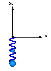
In the following figure a typical animation of the spring is shown. The blue sphere in the middle of the spring characterizes the location of the point mass.
Extends from Interfaces.PartialTwoFrames (Base model for components providing two frame connectors + outer world + assert to guarantee that the component is connected).
| Type | Name | Default | Description |
|---|---|---|---|
| Boolean | animation | true | = true, if animation shall be enabled |
| Boolean | showMass | true | = true, if point mass shall be visualized as sphere if animation=true and m>0 |
| TranslationalSpringConstant | c | Spring constant [N/m] | |
| Length | s_unstretched | 0 | Unstretched spring length [m] |
| Mass | m | 0 | Spring mass located on the connetion line between the origin of frame_a and the origin of frame_b [kg] |
| Real | lengthFraction | 0.5 | Location of spring mass with respect to frame_a as a fraction of the distance from frame_a to frame_b (=0: at frame_a; =1: at frame_b) |
| Animation | |||
| if animation = true | |||
| Distance | width | world.defaultForceWidth | Width of spring [m] |
| Distance | coilWidth | width/10 | Width of spring coil [m] |
| Integer | numberOfWindings | 5 | Number of spring windings |
| Color | color | Modelica.Mechanics.MultiBody... | Color of spring |
| SpecularCoefficient | specularCoefficient | world.defaultSpecularCoeffic... | Reflection of ambient light (= 0: light is completely absorbed) |
| if animation = true and showMass = true | |||
| Diameter | massDiameter | max(0, (width - 2*coilWidth)... | Diameter of mass point sphere [m] |
| Color | massColor | Modelica.Mechanics.MultiBody... | Color of mass point |
| Advanced | |||
| If enabled, can give wrong results, see MultiBody.UsersGuide.Tutorial.ConnectionOfLineForces | |||
| Boolean | fixedRotationAtFrame_a | false | =true, if rotation frame_a.R is fixed (to directly connect line forces) |
| Boolean | fixedRotationAtFrame_b | false | =true, if rotation frame_b.R is fixed (to directly connect line forces) |
| Type | Name | Description |
|---|---|---|
| Frame_a | frame_a | Coordinate system fixed to the component with one cut-force and cut-torque |
| Frame_b | frame_b | Coordinate system fixed to the component with one cut-force and cut-torque |
model Spring "Linear translational spring with optional mass"
  import Modelica.Mechanics.MultiBody.Types;
  extends Interfaces.PartialTwoFrames;
  parameter Boolean animation=true "= true, if animation shall be enabled";
  parameter Boolean showMass=true
    "= true, if point mass shall be visualized as sphere if animation=true and m>0";

  parameter SI.TranslationalSpringConstant c(final min=0) "Spring constant";
  parameter SI.Length s_unstretched=0 "Unstretched spring length";
  parameter SI.Mass m(min=0)=0
    "Spring mass located on the connetion line between the origin of frame_a and the origin of frame_b";
  parameter Real lengthFraction(
    min=0,
    max=1) = 0.5
    "Location of spring mass with respect to frame_a as a fraction of the distance from frame_a to frame_b (=0: at frame_a; =1: at frame_b)";
  input SI.Distance width=world.defaultForceWidth " Width of spring";
  input SI.Distance coilWidth=width/10 " Width of spring coil";
  parameter Integer numberOfWindings=5 " Number of spring windings";
  input Types.Color color=Modelica.Mechanics.MultiBody.Types.Defaults.SpringColor
    " Color of spring";
  input Types.SpecularCoefficient specularCoefficient = world.defaultSpecularCoefficient
    "Reflection of ambient light (= 0: light is completely absorbed)";
  input SIunits.Diameter massDiameter=max(0, (width - 2*coilWidth)*0.9)
    " Diameter of mass point sphere";
  input Types.Color massColor=Modelica.Mechanics.MultiBody.Types.Defaults.BodyColor
    " Color of mass point";
  parameter Boolean fixedRotationAtFrame_a=false
    "=true, if rotation frame_a.R is fixed (to directly connect line forces)";
  parameter Boolean fixedRotationAtFrame_b=false
    "=true, if rotation frame_b.R is fixed (to directly connect line forces)";

  Forces.LineForceWithMass lineForce(
    animateLine=animation,
    animateMass=showMass,
    m=m,
    lengthFraction=lengthFraction,
    lineShapeType="spring",
    lineShapeHeight=coilWidth*2,
    lineShapeWidth=width,
    lineShapeExtra=numberOfWindings,
    lineShapeColor=color,
    specularCoefficient=specularCoefficient,
    massDiameter=massDiameter,
    massColor=massColor,
    fixedRotationAtFrame_a=fixedRotationAtFrame_a,
    fixedRotationAtFrame_b=fixedRotationAtFrame_b);
  Modelica.Mechanics.Translational.Components.Spring spring(
                                                 s_rel0=s_unstretched, c=c);

equation
  connect(lineForce.frame_a, frame_a);
  connect(lineForce.frame_b, frame_b);
  connect(spring.flange_b, lineForce.flange_b);
  connect(spring.flange_a, lineForce.flange_a);

end Spring;
 Modelica.Mechanics.MultiBody.Forces.Damper

Linear damper acting as line force between frame_a and frame_b. A force f is exerted on the origin of frame_b and with opposite sign on the origin of frame_a along the line from the origin of frame_a to the origin of frame_b according to the equation:
f = d*der(s);
where "d" is a parameter, "s" is the distance between the origin of frame_a and the origin of frame_b and der(s) is the time derivative of "s".
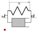
In the following figure a typical animation is shown where a mass is hanging on a damper.

Extends from Interfaces.PartialLineForce (Base model for line force elements), Modelica.Thermal.HeatTransfer.Interfaces.PartialElementaryConditionalHeatPort (Partial model to include a conditional HeatPort in order to dissipate losses, used for textual modeling, i.e., for elementary models).
| Type | Name | Default | Description |
|---|---|---|---|
| Boolean | animation | true | = true, if animation shall be enabled |
| TranslationalDampingConstant | d | Damping constant [N.s/m] | |
| Boolean | useHeatPort | false | =true, if heatPort is enabled |
| Temperature | T | 293.15 | Fixed device temperature if useHeatPort = false [K] |
| Animation | |||
| if animation = true | |||
| Distance | length_a | world.defaultForceLength | Length of cylinder at frame_a side [m] |
| Diameter | diameter_a | world.defaultForceWidth | Diameter of cylinder at frame_a side [m] |
| Diameter | diameter_b | 0.6*diameter_a | Diameter of cylinder at frame_b side [m] |
| Color | color_a | {100,100,100} | Color at frame_a |
| Color | color_b | {155,155,155} | Color at frame_b |
| SpecularCoefficient | specularCoefficient | world.defaultSpecularCoeffic... | Reflection of ambient light (= 0: light is completely absorbed) |
| Advanced | |||
| Position | s_small | 1.E-6 | Prevent zero-division if relative distance s=0 [m] |
| If enabled, can give wrong results, see MultiBody.UsersGuide.Tutorial.ConnectionOfLineForces | |||
| Boolean | fixedRotationAtFrame_a | false | =true, if rotation frame_a.R is fixed (to directly connect line forces) |
| Boolean | fixedRotationAtFrame_b | false | =true, if rotation frame_b.R is fixed (to directly connect line forces) |
| Type | Name | Description |
|---|---|---|
| Frame_a | frame_a | Coordinate system fixed to the force element with one cut-force and cut-torque |
| Frame_b | frame_b | Coordinate system fixed to the force element with one cut-force and cut-torque |
| HeatPort_a | heatPort | Optional port to which dissipated losses are transported in form of heat |
model Damper "Linear (velocity dependent) damper"
  import Modelica.Mechanics.MultiBody.Types;
  parameter Boolean animation=true "= true, if animation shall be enabled";
  parameter SI.TranslationalDampingConstant d(final min=0, start = 0)
    "Damping constant";
  parameter SI.Distance length_a=world.defaultForceLength
    " Length of cylinder at frame_a side";
  input SIunits.Diameter diameter_a=world.defaultForceWidth
    " Diameter of cylinder at frame_a side";
  input SIunits.Diameter diameter_b=0.6*diameter_a
    " Diameter of cylinder at frame_b side";
  input Types.Color color_a={100,100,100} " Color at frame_a";
  input Types.Color color_b={155,155,155} " Color at frame_b";
  input Types.SpecularCoefficient specularCoefficient = world.defaultSpecularCoefficient
    "Reflection of ambient light (= 0: light is completely absorbed)";
  extends Interfaces.PartialLineForce;
  extends Modelica.Thermal.HeatTransfer.Interfaces.PartialElementaryConditionalHeatPort
    (final T=293.15);
protected
  SI.Position r0_b[3]=e_a*noEvent(min(length_a, s));
  Visualizers.Advanced.Shape shape_a(
    shapeType="cylinder",
    color=color_a,
    specularCoefficient=specularCoefficient,
    length=noEvent(min(length_a, s)),
    width=diameter_a,
    height=diameter_a,
    lengthDirection=e_a,
    widthDirection={0,1,0},
    r=frame_a.r_0,
    R=frame_a.R) if
                   world.enableAnimation and animation;
  Visualizers.Advanced.Shape shape_b(
    shapeType="cylinder",
    color=color_b,
    specularCoefficient=specularCoefficient,
    length=noEvent(max(s - length_a, 0)),
    width=diameter_b,
    height=diameter_b,
    lengthDirection=e_a,
    widthDirection={0,1,0},
    r_shape=r0_b,
    r=frame_a.r_0,
    R=frame_a.R) if world.enableAnimation and animation;
equation
  f = d*der(s);
  lossPower = f*der(s);
end Damper;
 Modelica.Mechanics.MultiBody.Forces.SpringDamperParallel
Linear spring and dinear damper in parallel acting as line force between frame_a and frame_b. A force f is exerted on the origin of frame_b and with opposite sign on the origin of frame_a along the line from the origin of frame_a to the origin of frame_b according to the equation:
f = c*(s - s_unstretched) + d*der(s);
where "c", "s_unstretched" and "d" are parameters, "s" is the distance between the origin of frame_a and the origin of frame_b and der(s) is the time derivative of s.
Extends from Interfaces.PartialLineForce (Base model for line force elements), Modelica.Thermal.HeatTransfer.Interfaces.PartialElementaryConditionalHeatPort (Partial model to include a conditional HeatPort in order to dissipate losses, used for textual modeling, i.e., for elementary models).
| Type | Name | Default | Description |
|---|---|---|---|
| Boolean | animation | true | = true, if animation shall be enabled |
| TranslationalSpringConstant | c | Spring constant [N/m] | |
| Length | s_unstretched | 0 | Unstretched spring length [m] |
| TranslationalDampingConstant | d | 0 | Damping constant [N.s/m] |
| Boolean | useHeatPort | false | =true, if heatPort is enabled |
| Temperature | T | 293.15 | Fixed device temperature if useHeatPort = false [K] |
| Animation | |||
| if animation = true | |||
| Distance | width | world.defaultForceWidth | Width of spring [m] |
| Distance | coilWidth | width/10 | Width of spring coil [m] |
| Integer | numberOfWindings | 5 | Number of spring windings |
| Color | color | Modelica.Mechanics.MultiBody... | Color of spring |
| SpecularCoefficient | specularCoefficient | world.defaultSpecularCoeffic... | Reflection of ambient light (= 0: light is completely absorbed) |
| Advanced | |||
| Position | s_small | 1.E-6 | Prevent zero-division if relative distance s=0 [m] |
| If enabled, can give wrong results, see MultiBody.UsersGuide.Tutorial.ConnectionOfLineForces | |||
| Boolean | fixedRotationAtFrame_a | false | =true, if rotation frame_a.R is fixed (to directly connect line forces) |
| Boolean | fixedRotationAtFrame_b | false | =true, if rotation frame_b.R is fixed (to directly connect line forces) |
| Type | Name | Description |
|---|---|---|
| Frame_a | frame_a | Coordinate system fixed to the force element with one cut-force and cut-torque |
| Frame_b | frame_b | Coordinate system fixed to the force element with one cut-force and cut-torque |
| HeatPort_a | heatPort | Optional port to which dissipated losses are transported in form of heat |
model SpringDamperParallel
  "Linear spring and linear damper in parallel"
  import SI = Modelica.SIunits;
  import Modelica.Mechanics.MultiBody.Types;
  parameter Boolean animation=true "= true, if animation shall be enabled";
  parameter SI.TranslationalSpringConstant c(final min=0) "Spring constant";
  parameter SI.Length s_unstretched=0 "Unstretched spring length";
  parameter SI.TranslationalDampingConstant d(final min=0) = 0
    "Damping constant";
  input SI.Distance width=world.defaultForceWidth " Width of spring";
  input SI.Distance coilWidth=width/10 " Width of spring coil";
  parameter Integer numberOfWindings=5 " Number of spring windings";
  input Types.Color color=Modelica.Mechanics.MultiBody.Types.Defaults.SpringColor
    " Color of spring";
  input Types.SpecularCoefficient specularCoefficient = world.defaultSpecularCoefficient
    "Reflection of ambient light (= 0: light is completely absorbed)";
  extends Interfaces.PartialLineForce;
  extends Modelica.Thermal.HeatTransfer.Interfaces.PartialElementaryConditionalHeatPort
    (final T=293.15);

protected
  Modelica.SIunits.Force f_d "Damping force";
  Visualizers.Advanced.Shape shape(
    shapeType="spring",
    color=color,
    length=s,
    width=width,
    height=coilWidth*2,
    lengthDirection=e_a,
    widthDirection={0,1,0},
    extra=numberOfWindings,
    r=frame_a.r_0,
    R=frame_a.R) if world.enableAnimation and animation;
equation
  f_d = d*der(s);
  f = c*(s - s_unstretched) + f_d;
  lossPower = f_d*der(s);
end SpringDamperParallel;
 Modelica.Mechanics.MultiBody.Forces.SpringDamperSeries

Linear spring and linear damper in series connection acting as line force between frame_a and frame_b:
  frame_a --> damper ----> spring --> frame_b
          |              |
          |-- s_damper --|  (s_damper is the state variable of this system)
A force f is exerted on the origin of frame_b and with opposite sign on the origin of frame_a along the line from the origin of frame_a to the origin of frame_b according to the equations:
   f = c*(s - s_unstretched - s_damper);
   f = d*der(s_damper);
where "c", "s_unstretched" and "d" are parameters, "s" is the distance between the origin of frame_a and the origin of frame_b. "s_damper" is the length of the damper (= an internal state of this force element) and der(s_damper) is the time derivative of s_damper.
Extends from Interfaces.PartialLineForce (Base model for line force elements), Modelica.Thermal.HeatTransfer.Interfaces.PartialElementaryConditionalHeatPort (Partial model to include a conditional HeatPort in order to dissipate losses, used for textual modeling, i.e., for elementary models).
| Type | Name | Default | Description |
|---|---|---|---|
| TranslationalSpringConstant | c | Spring constant [N/m] | |
| Length | s_unstretched | 0 | Unstretched spring length [m] |
| TranslationalDampingConstant | d | 0 | Damping constant [N.s/m] |
| Length | s_damper_start | 0 | Initial length of damper [m] |
| Boolean | useHeatPort | false | =true, if heatPort is enabled |
| Temperature | T | 293.15 | Fixed device temperature if useHeatPort = false [K] |
| Advanced | |||
| Position | s_small | 1.E-6 | Prevent zero-division if relative distance s=0 [m] |
| If enabled, can give wrong results, see MultiBody.UsersGuide.Tutorial.ConnectionOfLineForces | |||
| Boolean | fixedRotationAtFrame_a | false | =true, if rotation frame_a.R is fixed (to directly connect line forces) |
| Boolean | fixedRotationAtFrame_b | false | =true, if rotation frame_b.R is fixed (to directly connect line forces) |
| Type | Name | Description |
|---|---|---|
| Frame_a | frame_a | Coordinate system fixed to the force element with one cut-force and cut-torque |
| Frame_b | frame_b | Coordinate system fixed to the force element with one cut-force and cut-torque |
| HeatPort_a | heatPort | Optional port to which dissipated losses are transported in form of heat |
model SpringDamperSeries
  "Linear spring and linear damper in series connection"
  import SI = Modelica.SIunits;
  parameter SI.TranslationalSpringConstant c(final min=0) "Spring constant";
  parameter SI.Length s_unstretched=0 "Unstretched spring length";
  parameter SI.TranslationalDampingConstant d(final min=0) = 0
    "Damping constant";
  parameter SI.Length s_damper_start=0 "Initial length of damper";
  SI.Position s_damper(start=s_damper_start, fixed=true)
    "Actual length of damper (frame_a - damper - spring - frame_b)";
  extends Interfaces.PartialLineForce;
  extends Modelica.Thermal.HeatTransfer.Interfaces.PartialElementaryConditionalHeatPort
    (final T=293.15);
equation
  f = c*(s - s_unstretched - s_damper);
  d*der(s_damper) = f;
  lossPower = f*der(s_damper);
end SpringDamperSeries;