This package contains utility components used by package Examples. Each component is built up hierarchically by components of the Gates package. In this way the Gates components were tested, and their usage is demonstrated.
Extends from Modelica.Icons.Package (Icon for standard packages).
| Name | Description |
|---|---|
| 4 to 1 Bit Multiplexer | |
| Unclocked RS FlipFlop | |
| Unclocked RS FlipFlop | |
| D FlipFlop | |
| JK FlipFlop | |
| Half adder | |
| Adding circuit for binary numbers with input carry bit | |
| Generic N Bit Adder | |
| 3 Bit Counter | |
| Generic N Bit Counter |
 Modelica.Electrical.Digital.Examples.Utilities.MUX4
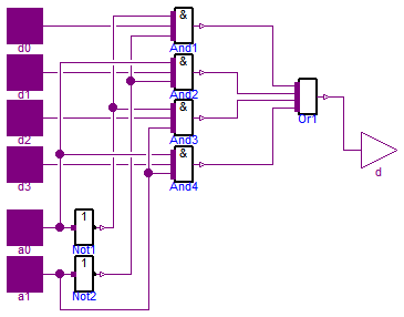
MUX4 is a four bit multiplexer which is built up by And, Not, and Or gates according to the schematic.
The parameters delayTime and q0 are prepared but not yet used in the component. The MUX4 component uses standard values in its components.
| Type | Name | Default | Description |
|---|---|---|---|
| Time | delayTime | 0.001 | Delay time [s] |
| Logic | q0 | L.'0' | Initial value |
| Type | Name | Description |
|---|---|---|
| input DigitalInput | d0 | |
| input DigitalInput | d1 | |
| input DigitalInput | d2 | |
| input DigitalInput | d3 | |
| input DigitalInput | a0 | |
| input DigitalInput | a1 | |
| output DigitalOutput | d |
model MUX4 "4 to 1 Bit Multiplexer" import D = Modelica.Electrical.Digital; import L = Modelica.Electrical.Digital.Interfaces.Logic; parameter Modelica.SIunits.Time delayTime=0.001 "Delay time"; parameter D.Interfaces.Logic q0=L.'0' "Initial value";D.Interfaces.DigitalInput d0; D.Interfaces.DigitalInput d1; D.Interfaces.DigitalInput d2; D.Interfaces.DigitalInput d3; D.Interfaces.DigitalInput a0; D.Interfaces.DigitalInput a1; D.Interfaces.DigitalOutput d; D.Basic.Or Or1(n=4); D.Basic.And And1(n=3); D.Basic.And And2(n=3); D.Basic.And And3(n=3); D.Basic.And And4(n=3); D.Basic.Not Not1; D.Basic.Not Not2; equationconnect(a0, Not1.x); connect(a1, Not2.x); connect(d0, And1.x[2]); connect(d1, And2.x[2]); connect(d2, And3.x[2]); connect(d3, And4.x[2]); connect(And4.y, Or1.x[1]); connect(And3.y, Or1.x[2]); connect(And2.y, Or1.x[3]); connect(And1.y, Or1.x[4]); connect(Or1.y, d); connect(Not1.y, And1.x[3]); connect(Not1.y, And3.x[3]); connect(Not2.y, And1.x[1]); connect(Not2.y, And2.x[1]); connect(a0, And4.x[3]); connect(a0, And2.x[3]); connect(a1, And4.x[1]); connect(a1, And3.x[1]); end MUX4;
 Modelica.Electrical.Digital.Examples.Utilities.RS
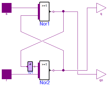
RS is a basic component for e.g., the RS (set-reset) flipflop, which is built up by Nor gates according to the schematic. To avoid a numerical loop a small transport delay is inserted which delay time is a parameter of the RS component. Also its initial value can be set by parameter.
| Type | Name | Default | Description |
|---|---|---|---|
| Time | delayTime | 0 | Delay time [s] |
| Logic | q0 | L.'U' | Initial value of output |
| Type | Name | Description |
|---|---|---|
| input DigitalInput | s | |
| input DigitalInput | r | |
| output DigitalOutput | q | |
| output DigitalOutput | qn |
model RS "Unclocked RS FlipFlop" import D = Modelica.Electrical.Digital; import L = Modelica.Electrical.Digital.Interfaces.Logic; parameter Modelica.SIunits.Time delayTime=0 "Delay time"; parameter D.Interfaces.Logic q0=L.'U' "Initial value of output";D.Basic.Nor Nor1; D.Basic.Nor Nor2; D.Interfaces.DigitalInput s; D.Interfaces.DigitalInput r; D.Interfaces.DigitalOutput q; D.Interfaces.DigitalOutput qn; D.Delay.TransportDelay TD1(delayTime=delayTime,y0=q0); equationconnect(s, Nor1.x[2]); connect(r, Nor2.x[1]); connect(Nor2.y, Nor1.x[1]); connect(Nor1.y,qn); connect(Nor2.y,q); connect(TD1.y, Nor2.x[2]); connect(TD1.x, Nor1.y); end RS;
 Modelica.Electrical.Digital.Examples.Utilities.RSFF
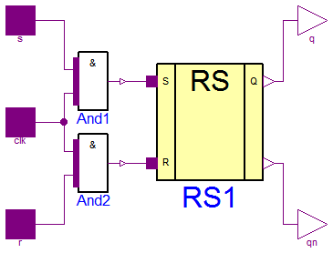
Basing on the RS component RSFF is a RS (set-reset) flipflop composed according the schematic. Its parameter delayTime is the delay time of the RS component transport delay, q0 is the initial value of that delay.
| Type | Name | Default | Description |
|---|---|---|---|
| Time | delayTime | 0.01 | Delay time [s] |
| Logic | q0 | L.'U' | Initial value |
| Type | Name | Description |
|---|---|---|
| input DigitalInput | s | |
| input DigitalInput | r | |
| output DigitalOutput | q | |
| output DigitalOutput | qn | not Q |
| input DigitalInput | clk |
model RSFF "Unclocked RS FlipFlop" import D = Modelica.Electrical.Digital; import L = Modelica.Electrical.Digital.Interfaces.Logic; parameter Modelica.SIunits.Time delayTime=0.01 "Delay time"; parameter D.Interfaces.Logic q0=L.'U' "Initial value";D.Interfaces.DigitalInput s; D.Interfaces.DigitalInput r; D.Interfaces.DigitalOutput q; D.Interfaces.DigitalOutput qn "not Q"; D.Interfaces.DigitalInput clk; D.Examples.Utilities.RS RS1(delayTime=delayTime,q0=q0); D.Basic.And And1; D.Basic.And And2; equationconnect(And2.y, RS1.r); connect(And1.y, RS1.s); connect(s, And1.x[2]); connect(clk, And1.x[1]); connect(clk, And2.x[2]); connect(r, And2.x[1]); connect(RS1.q,q); connect(RS1.qn,qn); end RSFF;
 Modelica.Electrical.Digital.Examples.Utilities.DFF
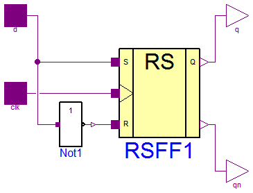
Basing on the RS component DFF is a D flipflop composed according the schematic. Its parameter delayTime is the delay time of the RS component transport delay, q0 is the initial value of that delay.
| Type | Name | Default | Description |
|---|---|---|---|
| Time | Tdel | 0.01 | Delay time [s] |
| Logic | QInit | L.'U' | Initial value |
| Type | Name | Description |
|---|---|---|
| input DigitalInput | d | |
| output DigitalOutput | q | |
| output DigitalOutput | qn | not Q |
| input DigitalInput | clk |
model DFF "D FlipFlop" import D = Modelica.Electrical.Digital; import L = Modelica.Electrical.Digital.Interfaces.Logic; parameter Modelica.SIunits.Time Tdel=0.01 "Delay time"; parameter L QInit=L.'U' "Initial value";D.Interfaces.DigitalInput d; D.Interfaces.DigitalOutput q; D.Interfaces.DigitalOutput qn "not Q"; D.Interfaces.DigitalInput clk; D.Examples.Utilities.RSFF RSFF1; D.Basic.Not Not1; equationconnect(RSFF1.q,q); connect(RSFF1.qn,qn); connect(Not1.y, RSFF1.r); connect(clk, RSFF1.clk); connect(d, Not1.x); connect(d, RSFF1.s); end DFF;
 Modelica.Electrical.Digital.Examples.Utilities.JKFF
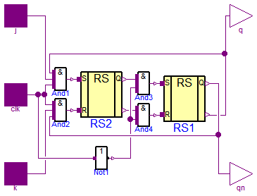
Basing on the RS component JKFF is a J-K-flipflop composed according the schematic. Its parameter delayTime is the delay time of the RS component transport delay, q0 is the initial value of that delay.
| Type | Name | Default | Description |
|---|---|---|---|
| Time | delayTime | 0.001 | Delay time [s] |
| Logic | q0 | L.'0' | Initial value |
| Type | Name | Description |
|---|---|---|
| input DigitalInput | j | |
| output DigitalOutput | q | |
| output DigitalOutput | qn | not Q |
| input DigitalInput | clk | |
| input DigitalInput | k |
model JKFF "JK FlipFlop" import D = Modelica.Electrical.Digital; import L = Modelica.Electrical.Digital.Interfaces.Logic; parameter Modelica.SIunits.Time delayTime=0.001 "Delay time"; parameter D.Interfaces.Logic q0=L.'0' "Initial value";D.Interfaces.DigitalInput j; D.Interfaces.DigitalOutput q; D.Interfaces.DigitalOutput qn "not Q"; D.Interfaces.DigitalInput clk; D.Interfaces.DigitalInput k; D.Examples.Utilities.RS RS1(delayTime=delayTime,q0=q0); D.Examples.Utilities.RS RS2(delayTime=delayTime,q0=q0); D.Basic.And And1(n=3); D.Basic.And And2(n=3); D.Basic.And And3; D.Basic.And And4; D.Basic.Not Not1; equationconnect(And2.y, RS2.r); connect(And1.y, RS2.s); connect(clk, And2.x[3]); connect(clk, And1.x[1]); connect(k, And2.x[2]); connect(And4.y, RS1.r); connect(And3.y, RS1.s); connect(RS2.qn, And4.x[2]); connect(RS2.q, And3.x[2]); connect(clk, Not1.x); connect(Not1.y, And3.x[1]); connect(Not1.y, And4.x[1]); connect(j, And1.x[2]); connect(RS1.q, And2.x[1]); connect(RS1.qn, And1.x[3]); connect(RS1.qn, q); connect(RS1.q, qn); end JKFF;
 Modelica.Electrical.Digital.Examples.Utilities.HalfAdder

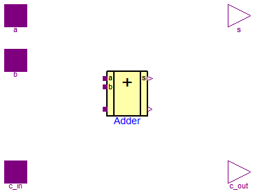
HalfAdder is a two bit adder which is composed by Gates components.
Its logic behavior is like this:
HalfAdder behavior
input a |
input b |
sum s |
carry c |
0 |
0 |
0 |
0 |
1 |
0 |
1 |
0 |
0 |
1 |
1 |
0 |
1 |
1 |
0 |
1 |
The parameter delayTime is the delay time (tLH=tHL) of both the components.
| Type | Name | Default | Description |
|---|---|---|---|
| Real | delayTime | 0 | Delay time |
| Type | Name | Description |
|---|---|---|
| input DigitalInput | b | |
| output DigitalOutput | s | |
| input DigitalInput | a | |
| output DigitalOutput | c |
model HalfAdder "Half adder" parameter Real delayTime=0 "Delay time";Modelica.Electrical.Digital.Interfaces.DigitalInput b; Modelica.Electrical.Digital.Interfaces.DigitalOutput s; Modelica.Electrical.Digital.Interfaces.DigitalInput a; Modelica.Electrical.Digital.Interfaces.DigitalOutput c; Modelica.Electrical.Digital.Gates.AndGate AND(tLH=delayTime, tHL=delayTime); Modelica.Electrical.Digital.Gates.XorGate XOR(tLH=delayTime, tHL=delayTime); equationconnect(AND.y, c); connect(XOR.y, s); connect(b, AND.x[1]); connect(b, XOR.x[1]); connect(a, XOR.x[2]); connect(a, AND.x[2]); end HalfAdder;
 Modelica.Electrical.Digital.Examples.Utilities.FullAdder
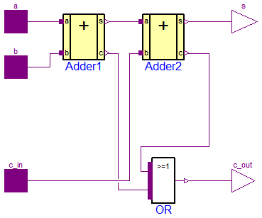
FullAdder is a two bit adder with additional carry in bit which is composed by Gates components.
Its logic behavior is like this:
FullAdder behavior
input a |
input b |
input carry c_in |
sum s |
output carry c_out |
0 |
0 |
0 |
0 |
0 |
1 |
0 |
0 |
1 |
0 |
0 |
1 |
0 |
1 |
0 |
1 |
1 |
0 |
0 |
1 |
0 |
0 |
1 |
0 |
1 |
1 |
0 |
1 |
0 |
1 |
0 |
1 |
1 |
0 |
1 |
1 |
1 |
1 |
1 |
1 |
| Type | Name | Description |
|---|---|---|
| input DigitalInput | a | |
| input DigitalInput | b | |
| input DigitalInput | c_in | |
| output DigitalOutput | s | |
| output DigitalOutput | c_out |
model FullAdder "Adding circuit for binary numbers with input carry bit"HalfAdder Adder2(delayTime=0.001); HalfAdder Adder1(delayTime=0.001); Modelica.Electrical.Digital.Interfaces.DigitalInput a; Modelica.Electrical.Digital.Interfaces.DigitalInput b; Modelica.Electrical.Digital.Interfaces.DigitalInput c_in; Modelica.Electrical.Digital.Interfaces.DigitalOutput s; Modelica.Electrical.Digital.Interfaces.DigitalOutput c_out; Modelica.Electrical.Digital.Basic.Or OR; equationconnect(c_out, OR.y); connect(Adder2.c, OR.x[2]); connect(Adder2.s, s); connect(Adder1.a, a); connect(b, Adder1.b); connect(Adder1.s, Adder2.a); connect(Adder1.c, OR.x[1]); connect(c_in, Adder2.b); end FullAdder;
 Modelica.Electrical.Digital.Examples.Utilities.Adder
The Adder is a generic n bit adder which is composed as a chain of FullAdder components. n can be chosen by the user, a and b are the n bit input vectors, s is the sum vector, and c_out is the carry bit of the "highes" FullAdder. All components are built up by Gate components.
| Type | Name | Default | Description |
|---|---|---|---|
| Integer | n | 2 | Number of single adders |
| Type | Name | Description |
|---|---|---|
| input DigitalInput | a[n] | |
| input DigitalInput | b[n] | |
| input DigitalInput | c_in | |
| output DigitalOutput | s[n] | |
| output DigitalOutput | c_out |
model Adder "Generic N Bit Adder" import Modelica.Electrical.Digital; parameter Integer n=2 "Number of single adders";Modelica.Electrical.Digital.Examples.Utilities.FullAdder Adder[n]; Modelica.Electrical.Digital.Interfaces.DigitalInput a[n]; Modelica.Electrical.Digital.Interfaces.DigitalInput b[n]; Modelica.Electrical.Digital.Interfaces.DigitalInput c_in; Modelica.Electrical.Digital.Interfaces.DigitalOutput s[n]; Modelica.Electrical.Digital.Interfaces.DigitalOutput c_out; equation connect(c_in,Adder[1].c_in); for i in 1:n loop connect(a[i],Adder[i].a); connect(b[i],Adder[i].b); connect(Adder[i].a,s[i]); if i>1 then connect(Adder[i-1].c_out,Adder[i].c_in); end if; end for; connect(Adder[n].c_out,c_out);end Adder;
 Modelica.Electrical.Digital.Examples.Utilities.Counter3
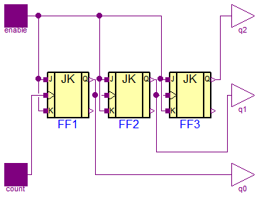
The Counter3 counts the high-low slopes of the count signal, if the enable signal is set to be true. It is composed by three JK flipflops. q0, q1, and q2 are the bits of the resulting number, where q0 is the lowest, and q2 the highest bit.
| Type | Name | Description |
|---|---|---|
| input DigitalInput | enable | |
| output DigitalOutput | q2 | |
| input DigitalInput | count | |
| output DigitalOutput | q1 | |
| output DigitalOutput | q0 |
model Counter3 "3 Bit Counter" import D = Modelica.Electrical.Digital; import L = Modelica.Electrical.Digital.Interfaces.Logic;D.Interfaces.DigitalInput enable; D.Interfaces.DigitalOutput q2; D.Interfaces.DigitalInput count; D.Examples.Utilities.JKFF FF1; D.Examples.Utilities.JKFF FF2; D.Examples.Utilities.JKFF FF3; D.Interfaces.DigitalOutput q1; D.Interfaces.DigitalOutput q0; equationconnect(enable, FF1.j); connect(enable, FF1.k); connect(count, FF1.clk); connect(FF1.q, FF2.clk); connect(FF2.q, FF3.clk); connect(FF2.j, enable); connect(FF2.k, FF2.j); connect(FF3.k, FF3.j); connect(FF3.j, enable); connect(FF3.q, q2); connect(FF1.q, q0); connect(FF2.q, q1); end Counter3;
 Modelica.Electrical.Digital.Examples.Utilities.Counter
The Counter is a generic component, which counts the high-low slopes of the count signal, if the enable signal is set to be true. It is composed by n JK flipflops. q is the resulting number, where q[0] is the lowest, and q[n] the highest bit.
| Type | Name | Default | Description |
|---|---|---|---|
| Integer | n | 3 | Number of bits |
| Time | delayTime | 0.001 | Delay of each JKFF [s] |
| Logic | q0 | L.'0' | Initial value |
| Type | Name | Description |
|---|---|---|
| input DigitalInput | enable | |
| input DigitalInput | count | |
| output DigitalOutput | q[n] |
model Counter "Generic N Bit Counter" import D = Modelica.Electrical.Digital; import L = Modelica.Electrical.Digital.Interfaces.Logic; parameter Integer n=3 "Number of bits"; parameter Modelica.SIunits.Time delayTime=0.001 "Delay of each JKFF"; parameter D.Interfaces.Logic q0=L.'0' "Initial value";D.Interfaces.DigitalInput enable; D.Interfaces.DigitalInput count; D.Examples.Utilities.JKFF FF[n](each delayTime=delayTime,each q0=q0);D.Interfaces.DigitalOutput q[n]; equation connect(enable,FF[1].j); connect(enable,FF[1].k); connect(count,FF[1].clk); connect(FF[1].q,q[1]); for i in 2:n loop connect(enable,FF[i].j); connect(enable,FF[i].k); connect(FF[i-1].q,FF[i].clk); connect(FF[i].q,q[i]); end for;end Counter;