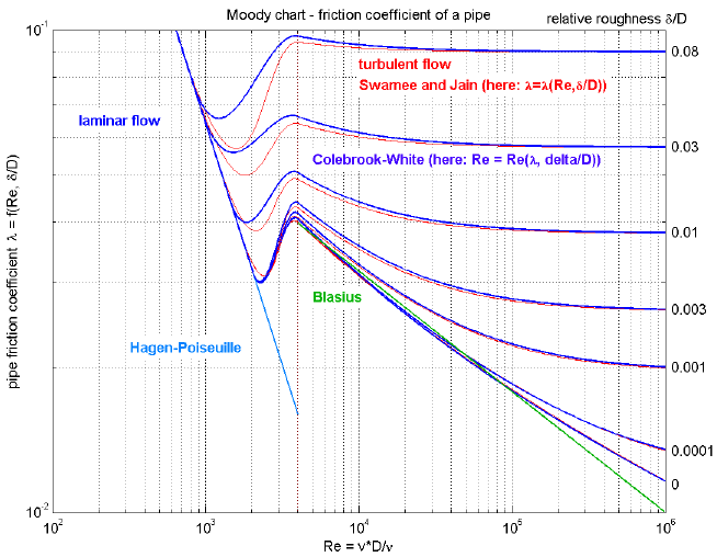
This component defines the complete regime of wall friction. The details are described in the UsersGuide. The functional relationship of the friction loss factor λ is displayed in the next figure. Function massFlowRate_dp() defines the "red curve" ("Swamee and Jain"), where as function pressureLoss_m_flow() defines the "blue curve" ("Colebrook-White"). The two functions are inverses from each other and give slightly different results in the transition region between Re = 1500 .. 4000, in order to get explicit equations without solving a non-linear equation.

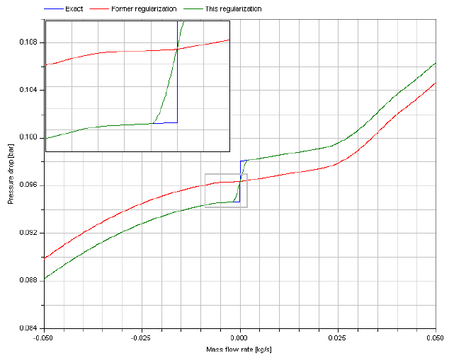
Additionally to wall friction, this component properly implements static head. With respect to the latter, two cases can be distinguished. In the case shown next, the change of elevation with the path from a to b has the opposite sign of the change of density.

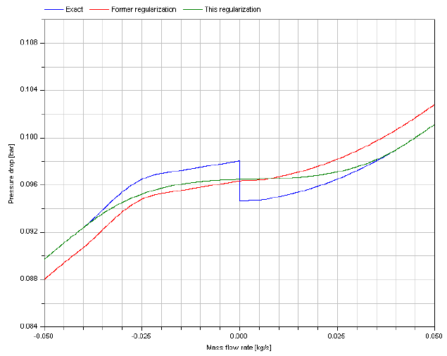
In the case illustrated second, the change of elevation with the path from a to b has the same sign of the change of density.

Extends from PartialWallFriction (Partial wall friction characteristic (base package of all wall friction characteristics)).
| Name | Description |
|---|---|
| Return mass flow rate m_flow as function of pressure loss dp, i.e., m_flow = f(dp), due to wall friction | |
| Return pressure loss dp as function of mass flow rate m_flow, i.e., dp = f(m_flow), due to wall friction | |
| Return mass flow rate m_flow as function of pressure loss dp, i.e., m_flow = f(dp), due to wall friction and static head | |
| Return pressure loss dp as function of mass flow rate m_flow, i.e., dp = f(m_flow), due to wall friction and static head | |
| Functions to calculate mass flow rate from friction pressure drop and vice versa | |
| Inherited | |
| use_mu=true | = true, if mu_a/mu_b are used in function, otherwise value is not used |
| use_roughness=true | = true, if roughness is used in function, otherwise value is not used |
| use_dp_small=true | = true, if dp_small is used in function, otherwise value is not used |
| use_m_flow_small=true | = true, if m_flow_small is used in function, otherwise value is not used |
| dp_is_zero=false | = true, if no wall friction is present, i.e., dp = 0 (function massFlowRate_dp() cannot be used) |
 Modelica.Fluid.Pipes.BaseClasses.WallFriction.Detailed.massFlowRate_dp
Extends from (Return mass flow rate m_flow as function of pressure loss dp, i.e., m_flow = f(dp), due to wall friction).
| Type | Name | Default | Description |
|---|---|---|---|
| Pressure | dp | Pressure loss (dp = port_a.p - port_b.p) [Pa] | |
| Density | rho_a | Density at port_a [kg/m3] | |
| Density | rho_b | Density at port_b [kg/m3] | |
| DynamicViscosity | mu_a | Dynamic viscosity at port_a (dummy if use_mu = false) [Pa.s] | |
| DynamicViscosity | mu_b | Dynamic viscosity at port_b (dummy if use_mu = false) [Pa.s] | |
| Length | length | Length of pipe [m] | |
| Diameter | diameter | Inner (hydraulic) diameter of pipe [m] | |
| Length | roughness | 2.5e-5 | Absolute roughness of pipe, with a default for a smooth steel pipe (dummy if use_roughness = false) [m] |
| AbsolutePressure | dp_small | 1 | Turbulent flow if |dp| >= dp_small (dummy if use_dp_small = false) [Pa] |
| Type | Name | Description |
|---|---|---|
| MassFlowRate | m_flow | Mass flow rate from port_a to port_b [kg/s] |
redeclare function extends massFlowRate_dp
"Return mass flow rate m_flow as function of pressure loss dp, i.e., m_flow = f(dp), due to wall friction"
import Modelica.Math;
protected
constant Real pi = Modelica.Constants.pi;
Real Delta = roughness/diameter "Relative roughness";
SI.ReynoldsNumber Re1 = (745*Math.exp(if Delta <= 0.0065 then 1 else 0.0065/Delta))^0.97
"Re leaving laminar curve";
SI.ReynoldsNumber Re2 = 4000 "Re entering turbulent curve";
SI.DynamicViscosity mu "Upstream viscosity";
SI.Density rho "Upstream density";
SI.ReynoldsNumber Re "Reynolds number";
Real lambda2 "Modified friction coefficient (= lambda*Re^2)";
function interpolateInRegion2
input Real Re_turbulent;
input SI.ReynoldsNumber Re1;
input SI.ReynoldsNumber Re2;
input Real Delta;
input Real lambda2;
output SI.ReynoldsNumber Re;
// point lg(lambda2(Re1)) with derivative at lg(Re1)
protected
Real x1=Math.log10(64*Re1);
Real y1=Math.log10(Re1);
Real yd1=1;
// Point lg(lambda2(Re2)) with derivative at lg(Re2)
Real aux1=(0.5/Math.log(10))*5.74*0.9;
Real aux2=Delta/3.7 + 5.74/Re2^0.9;
Real aux3=Math.log10(aux2);
Real L2=0.25*(Re2/aux3)^2;
Real aux4=2.51/sqrt(L2) + 0.27*Delta;
Real aux5=-2*sqrt(L2)*Math.log10(aux4);
Real x2=Math.log10(L2);
Real y2=Math.log10(aux5);
Real yd2=0.5 + (2.51/Math.log(10))/(aux5*aux4);
// Constants: Cubic polynomial between lg(Re1) and lg(Re2)
Real diff_x=x2 - x1;
Real m=(y2 - y1)/diff_x;
Real c2=(3*m - 2*yd1 - yd2)/diff_x;
Real c3=(yd1 + yd2 - 2*m)/(diff_x*diff_x);
Real lambda2_1=64*Re1;
Real dx;
algorithm
dx := Math.log10(lambda2/lambda2_1);
Re := Re1*(lambda2/lambda2_1)^(1 + dx*(c2 + dx*c3));
end interpolateInRegion2 ;
algorithm
// Determine upstream density, upstream viscosity, and lambda2
rho := if dp >= 0 then rho_a else rho_b;
mu := if dp >= 0 then mu_a else mu_b;
lambda2 := abs(dp)*2*diameter^3*rho/(length*mu*mu);
// Determine Re under the assumption of laminar flow
Re := lambda2/64;
// Modify Re, if turbulent flow
if Re > Re1 then
Re :=-2*sqrt(lambda2)*Math.log10(2.51/sqrt(lambda2) + 0.27*Delta);
if Re < Re2 then
Re := interpolateInRegion2(Re, Re1, Re2, Delta, lambda2);
end if;
end if;
// Determine mass flow rate
m_flow := (pi*diameter/4)*mu*(if dp >= 0 then Re else -Re);
end massFlowRate_dp;
 Modelica.Fluid.Pipes.BaseClasses.WallFriction.Detailed.pressureLoss_m_flow
Extends from (Return pressure loss dp as function of mass flow rate m_flow, i.e., dp = f(m_flow), due to wall friction).
| Type | Name | Default | Description |
|---|---|---|---|
| MassFlowRate | m_flow | Mass flow rate from port_a to port_b [kg/s] | |
| Density | rho_a | Density at port_a [kg/m3] | |
| Density | rho_b | Density at port_b [kg/m3] | |
| DynamicViscosity | mu_a | Dynamic viscosity at port_a (dummy if use_mu = false) [Pa.s] | |
| DynamicViscosity | mu_b | Dynamic viscosity at port_b (dummy if use_mu = false) [Pa.s] | |
| Length | length | Length of pipe [m] | |
| Diameter | diameter | Inner (hydraulic) diameter of pipe [m] | |
| Length | roughness | 2.5e-5 | Absolute roughness of pipe, with a default for a smooth steel pipe (dummy if use_roughness = false) [m] |
| MassFlowRate | m_flow_small | 0.01 | Turbulent flow if |m_flow| >= m_flow_small (dummy if use_m_flow_small = false) [kg/s] |
| Type | Name | Description |
|---|---|---|
| Pressure | dp | Pressure loss (dp = port_a.p - port_b.p) [Pa] |
redeclare function extends pressureLoss_m_flow
"Return pressure loss dp as function of mass flow rate m_flow, i.e., dp = f(m_flow), due to wall friction"
import Modelica.Math;
protected
constant Real pi = Modelica.Constants.pi;
Real Delta = roughness/diameter "Relative roughness";
SI.ReynoldsNumber Re1 = 745*Math.exp(if Delta <= 0.0065 then 1 else 0.0065/Delta)
"Re leaving laminar curve";
SI.ReynoldsNumber Re2 = 4000 "Re entering turbulent curve";
SI.DynamicViscosity mu "Upstream viscosity";
SI.Density rho "Upstream density";
SI.ReynoldsNumber Re "Reynolds number";
Real lambda2 "Modified friction coefficient (= lambda*Re^2)";
function interpolateInRegion2
input SI.ReynoldsNumber Re;
input SI.ReynoldsNumber Re1;
input SI.ReynoldsNumber Re2;
input Real Delta;
output Real lambda2;
// point lg(lambda2(Re1)) with derivative at lg(Re1)
protected
Real x1 = Math.log10(Re1);
Real y1 = Math.log10(64*Re1);
Real yd1=1;
// Point lg(lambda2(Re2)) with derivative at lg(Re2)
Real aux1=(0.5/Math.log(10))*5.74*0.9;
Real aux2=Delta/3.7 + 5.74/Re2^0.9;
Real aux3=Math.log10(aux2);
Real L2=0.25*(Re2/aux3)^2;
Real aux4=2.51/sqrt(L2) + 0.27*Delta;
Real aux5=-2*sqrt(L2)*Math.log10(aux4);
Real x2 = Math.log10(Re2);
Real y2 = Math.log10(L2);
Real yd2 = 2 + 4*aux1/(aux2*aux3*(Re2)^0.9);
// Constants: Cubic polynomial between lg(Re1) and lg(Re2)
Real diff_x=x2 - x1;
Real m=(y2 - y1)/diff_x;
Real c2=(3*m - 2*yd1 - yd2)/diff_x;
Real c3=(yd1 + yd2 - 2*m)/(diff_x*diff_x);
Real dx;
algorithm
dx := Math.log10(Re/Re1);
lambda2 := 64*Re1*(Re/Re1)^(1 + dx*(c2 + dx*c3));
end interpolateInRegion2 ;
algorithm
// Determine upstream density and upstream viscosity
rho :=if m_flow >= 0 then rho_a else rho_b;
mu :=if m_flow >= 0 then mu_a else mu_b;
// Determine Re, lambda2 and pressure drop
Re :=(4/pi)*abs(m_flow)/(diameter*mu);
lambda2 := if Re <= Re1 then 64*Re else
(if Re >= Re2 then 0.25*(Re/Math.log10(Delta/3.7 + 5.74/Re^0.9))^2 else
interpolateInRegion2(Re, Re1, Re2, Delta));
dp :=length*mu*mu/(2*rho*diameter*diameter*diameter)*
(if m_flow >= 0 then lambda2 else -lambda2);
end pressureLoss_m_flow;
 Modelica.Fluid.Pipes.BaseClasses.WallFriction.Detailed.massFlowRate_dp_staticHead
| Type | Name | Default | Description |
|---|---|---|---|
| Pressure | dp | Pressure loss (dp = port_a.p - port_b.p) [Pa] | |
| Density | rho_a | Density at port_a [kg/m3] | |
| Density | rho_b | Density at port_b [kg/m3] | |
| DynamicViscosity | mu_a | Dynamic viscosity at port_a (dummy if use_mu = false) [Pa.s] | |
| DynamicViscosity | mu_b | Dynamic viscosity at port_b (dummy if use_mu = false) [Pa.s] | |
| Length | length | Length of pipe [m] | |
| Diameter | diameter | Inner (hydraulic) diameter of pipe [m] | |
| Real | g_times_height_ab | Gravity times (Height(port_b) - Height(port_a)) | |
| Length | roughness | 2.5e-5 | Absolute roughness of pipe, with a default for a smooth steel pipe (dummy if use_roughness = false) [m] |
| AbsolutePressure | dp_small | 1 | Turbulent flow if |dp| >= dp_small (dummy if use_dp_small = false) [Pa] |
| Type | Name | Description |
|---|---|---|
| MassFlowRate | m_flow | Mass flow rate from port_a to port_b [kg/s] |
redeclare function extends massFlowRate_dp_staticHead
  "Return mass flow rate m_flow as function of pressure loss dp, i.e., m_flow = f(dp), due to wall friction and static head"

protected
  Real Delta = roughness/diameter "Relative roughness";
  SI.ReynoldsNumber Re "Reynolds number";
  SI.ReynoldsNumber Re1 = (745*exp(if Delta <= 0.0065 then 1 else 0.0065/Delta))^0.97
    "Boundary between laminar regime and transition";
  constant SI.ReynoldsNumber Re2 = 4000
    "Boundary between transition and turbulent regime";
  SI.Pressure dp_a
    "Upper end of regularization domain of the m_flow(dp) relation";
  SI.Pressure dp_b
    "Lower end of regularization domain of the m_flow(dp) relation";
  SI.MassFlowRate m_flow_a "Value at upper end of regularization domain";
  SI.MassFlowRate m_flow_b "Value at lower end of regularization domain";

  SI.MassFlowRate dm_flow_ddp_fric_a
    "Derivative at upper end of regularization domain";
  SI.MassFlowRate dm_flow_ddp_fric_b
    "Derivative at lower end of regularization domain";

  SI.Pressure dp_grav_a = g_times_height_ab*rho_a
    "Static head if mass flows in design direction (a to b)";
  SI.Pressure dp_grav_b = g_times_height_ab*rho_b
    "Static head if mass flows against design direction (b to a)";

  // Properly define zero mass flow conditions
  SI.MassFlowRate m_flow_zero = 0;
  SI.Pressure dp_zero = (dp_grav_a + dp_grav_b)/2;
  Real dm_flow_ddp_fric_zero;

algorithm
  dp_a := max(dp_grav_a, dp_grav_b)+dp_small;
  dp_b := min(dp_grav_a, dp_grav_b)-dp_small;

  if dp>=dp_a then
    // Positive flow outside regularization
    m_flow := Internal.m_flow_of_dp_fric(dp-dp_grav_a, rho_a, rho_b, mu_a, mu_b, length, diameter, Re1, Re2, Delta);
  elseif dp<=dp_b then
    // Negative flow outside regularization
    m_flow := Internal.m_flow_of_dp_fric(dp-dp_grav_b, rho_a, rho_b, mu_a, mu_b, length, diameter, Re1, Re2, Delta);
  else
    // Regularization parameters
    (m_flow_a, dm_flow_ddp_fric_a) := Internal.m_flow_of_dp_fric(dp_a-dp_grav_a, rho_a, rho_b, mu_a, mu_b, length, diameter, Re1, Re2, Delta);
    (m_flow_b, dm_flow_ddp_fric_b) := Internal.m_flow_of_dp_fric(dp_b-dp_grav_b, rho_a, rho_b, mu_a, mu_b, length, diameter, Re1, Re2, Delta);
    // Include a properly defined zero mass flow point
    // Obtain a suitable slope from the linear section slope c (value of m_flow is overwritten later)
    (m_flow, dm_flow_ddp_fric_zero) := Utilities.regFun3(dp_zero, dp_b, dp_a, m_flow_b, m_flow_a, dm_flow_ddp_fric_b, dm_flow_ddp_fric_a);
    // Do regularization
    if dp>dp_zero then
      m_flow := Utilities.regFun3(dp, dp_zero, dp_a, m_flow_zero, m_flow_a, dm_flow_ddp_fric_zero, dm_flow_ddp_fric_a);
    else
      m_flow := Utilities.regFun3(dp, dp_b, dp_zero, m_flow_b, m_flow_zero, dm_flow_ddp_fric_b, dm_flow_ddp_fric_zero);
    end if;
  end if;
end massFlowRate_dp_staticHead;
 Modelica.Fluid.Pipes.BaseClasses.WallFriction.Detailed.pressureLoss_m_flow_staticHead
| Type | Name | Default | Description |
|---|---|---|---|
| MassFlowRate | m_flow | Mass flow rate from port_a to port_b [kg/s] | |
| Density | rho_a | Density at port_a [kg/m3] | |
| Density | rho_b | Density at port_b [kg/m3] | |
| DynamicViscosity | mu_a | Dynamic viscosity at port_a (dummy if use_mu = false) [Pa.s] | |
| DynamicViscosity | mu_b | Dynamic viscosity at port_b (dummy if use_mu = false) [Pa.s] | |
| Length | length | Length of pipe [m] | |
| Diameter | diameter | Inner (hydraulic) diameter of pipe [m] | |
| Real | g_times_height_ab | Gravity times (Height(port_b) - Height(port_a)) | |
| Length | roughness | 2.5e-5 | Absolute roughness of pipe, with a default for a smooth steel pipe (dummy if use_roughness = false) [m] |
| MassFlowRate | m_flow_small | 0.01 | Turbulent flow if |m_flow| >= m_flow_small (dummy if use_m_flow_small = false) [kg/s] |
| Type | Name | Description |
|---|---|---|
| Pressure | dp | Pressure loss (dp = port_a.p - port_b.p) [Pa] |
redeclare function extends pressureLoss_m_flow_staticHead
  "Return pressure loss dp as function of mass flow rate m_flow, i.e., dp = f(m_flow), due to wall friction and static head"

protected
  Real Delta = roughness/diameter "Relative roughness";
  SI.ReynoldsNumber Re1 = 745*exp(if Delta <= 0.0065 then 1 else 0.0065/Delta)
    "Boundary between laminar regime and transition";
  constant SI.ReynoldsNumber Re2 = 4000
    "Boundary between transition and turbulent regime";

  SI.MassFlowRate m_flow_a
    "Upper end of regularization domain of the dp(m_flow) relation";
  SI.MassFlowRate m_flow_b
    "Lower end of regularization domain of the dp(m_flow) relation";

  SI.Pressure dp_a "Value at upper end of regularization domain";
  SI.Pressure dp_b "Value at lower end of regularization domain";

  SI.Pressure dp_grav_a = g_times_height_ab*rho_a
    "Static head if mass flows in design direction (a to b)";
  SI.Pressure dp_grav_b = g_times_height_ab*rho_b
    "Static head if mass flows against design direction (b to a)";

  Real ddp_dm_flow_a
    "Derivative of pressure drop with mass flow rate at m_flow_a";
  Real ddp_dm_flow_b
    "Derivative of pressure drop with mass flow rate at m_flow_b";

  // Properly define zero mass flow conditions
  SI.MassFlowRate m_flow_zero = 0;
  SI.Pressure dp_zero = (dp_grav_a + dp_grav_b)/2;
  Real ddp_dm_flow_zero;

algorithm
  m_flow_a := if dp_grav_a<dp_grav_b then
    Internal.m_flow_of_dp_fric(dp_grav_b - dp_grav_a, rho_a, rho_b, mu_a, mu_b, length, diameter, Re1, Re2, Delta)+m_flow_small else
    m_flow_small;
  m_flow_b := if dp_grav_a<dp_grav_b then
    Internal.m_flow_of_dp_fric(dp_grav_a - dp_grav_b, rho_a, rho_b, mu_a, mu_b, length, diameter, Re1, Re2, Delta)-m_flow_small else
    -m_flow_small;

  if m_flow>=m_flow_a then
    // Positive flow outside regularization
    dp := Internal.dp_fric_of_m_flow(m_flow, rho_a, rho_b, mu_a, mu_b, length, diameter, Re1, Re2, Delta) + dp_grav_a;
  elseif m_flow<=m_flow_b then
    // Negative flow outside regularization
    dp := Internal.dp_fric_of_m_flow(m_flow, rho_a, rho_b, mu_a, mu_b, length, diameter, Re1, Re2, Delta) + dp_grav_b;
  else
    // Regularization parameters
    (dp_a, ddp_dm_flow_a) := Internal.dp_fric_of_m_flow(m_flow_a, rho_a, rho_b, mu_a, mu_b, length, diameter, Re1, Re2, Delta);
    dp_a := dp_a + dp_grav_a "Adding dp_grav to dp_fric to get dp";
    (dp_b, ddp_dm_flow_b) := Internal.dp_fric_of_m_flow(m_flow_b, rho_a, rho_b, mu_a, mu_b, length, diameter, Re1, Re2, Delta);
    dp_b := dp_b + dp_grav_b "Adding dp_grav to dp_fric to get dp";
    // Include a properly defined zero mass flow point
    // Obtain a suitable slope from the linear section slope c (value of dp is overwritten later)
    (dp, ddp_dm_flow_zero) := Utilities.regFun3(m_flow_zero, m_flow_b, m_flow_a, dp_b, dp_a, ddp_dm_flow_b, ddp_dm_flow_a);
    // Do regularization
    if m_flow>m_flow_zero then
      dp := Utilities.regFun3(m_flow, m_flow_zero, m_flow_a, dp_zero, dp_a, ddp_dm_flow_zero, ddp_dm_flow_a);
    else
      dp := Utilities.regFun3(m_flow, m_flow_b, m_flow_zero, dp_b, dp_zero, ddp_dm_flow_b, ddp_dm_flow_zero);
    end if;
  end if;
end pressureLoss_m_flow_staticHead;