This package contains electrical components with idealized behaviour:
Extends from Modelica.Icons.Library (Icon for library).
| Name | Description |
|---|---|
| Ideal thyristor | |
| Ideal GTO thyristor | |
| Ideal commuting switch | |
| Ideal intermediate switch | |
| Controlled ideal commuting switch | |
| Controlled ideal intermediate switch | |
| Ideal operational amplifier (norator-nullator pair) | |
| Ideal operational amplifier (norator-nullator pair), but 3 pins | |
| Ideal operational amplifier with limitation | |
| Ideal diode | |
| Ideal transformer core with or without magnetization | |
| Ideal gyrator | |
| Idle branch | |
| Short cut branch | |
| Ideal electrical opener | |
| Ideal electrical closer | |
| Controlled ideal electrical opener | |
| Controlled ideal electrical closer | |
| Ideal opening switch with simple arc model | |
| Ideal closing switch with simple arc model | |
| Controlled ideal electrical opener with simple arc model | |
| Controlled ideal electrical closer with simple arc model |
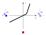
 Modelica.Electrical.Analog.Ideal.IdealThyristor
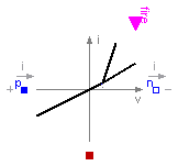
This is the behaviour if all parameters are exactly zero.
Note, there are circuits, where this ideal description
with zero resistance and zero cinductance is not possible.
In order to prevent singularities during switching, the opened
thyristor has a small conductance Goff and the closed thyristor has a low
resistance Ron which is default.
The parameter Vknee which is the forward threshold voltage, allows to displace
the knee point
along the Goff-characteristic until v = Vknee.
Please note:
In case of useHeatPort=true the temperature dependence of the electrical
behavior is not modelled. The parameters are not temperature dependent.
Extends from Modelica.Electrical.Analog.Interfaces.OnePort (Component with two electrical pins p and n and current i from p to n), Modelica.Electrical.Analog.Interfaces.ConditionalHeatPort (Partial model to include a conditional HeatPort in order to describe the power loss via a thermal network).
| Type | Name | Default | Description |
|---|---|---|---|
| Resistance | Ron | 1.E-5 | Closed thyristor resistance [Ohm] |
| Conductance | Goff | 1.E-5 | Opened thyristor conductance [S] |
| Voltage | Vknee | Forward threshold voltage [V] | |
| Boolean | useHeatPort | false | =true, if HeatPort is enabled |
| Temperature | T | 293.15 | Fixed device temperature if useHeatPort = false [K] |
| Type | Name | Description |
|---|---|---|
| PositivePin | p | Positive pin (potential p.v > n.v for positive voltage drop v) |
| NegativePin | n | Negative pin |
| HeatPort_a | heatPort | |
| input BooleanInput | fire |
model IdealThyristor "Ideal thyristor"
  extends Modelica.Electrical.Analog.Interfaces.OnePort;
  parameter Modelica.SIunits.Resistance Ron(final min=0) = 1.E-5
    "Closed thyristor resistance";
  parameter Modelica.SIunits.Conductance Goff(final min=0) = 1.E-5
    "Opened thyristor conductance";
  parameter Modelica.SIunits.Voltage Vknee(final min=0, start=0)
    "Forward threshold voltage";
  extends Modelica.Electrical.Analog.Interfaces.ConditionalHeatPort(final T=293.15);
  Boolean off(start=true) "Switching state";
  Modelica.Blocks.Interfaces.BooleanInput fire;
protected
  Real s(final unit="1")
    "Auxiliary variable: if on then current, if opened then voltage";
  constant Modelica.SIunits.Voltage unitVoltage= 1;
  constant Modelica.SIunits.Current unitCurrent= 1;
equation
  off = s < 0 or pre(off) and not fire;
  v = (s*unitCurrent)*(if off then 1 else Ron) + Vknee;
  i = (s*unitVoltage)*(if off then Goff else 1) + Goff*Vknee;
  LossPower = v*i;
end IdealThyristor;
Modelica.Electrical.Analog.Ideal.IdealGTOThyristor
This is the behaviour if all parameters are exactly zero.
Note, there are circuits, where this ideal description
with zero resistance and zero cinductance is not possible.
In order to prevent singularities during switching, the opened
thyristor has a small conductance Goff and the closed thyristor has a low
resistance Ron which is default.
The parameter Vknee which is the forward threshold voltage, allows to displace
the knee point
along the Goff-characteristic until v = Vknee.
Please note:
In case of useHeatPort=true the temperature dependence of the electrical
behavior is not modelled. The parameters are not temperature dependent.
Extends from Modelica.Electrical.Analog.Interfaces.OnePort (Component with two electrical pins p and n and current i from p to n), Modelica.Electrical.Analog.Interfaces.ConditionalHeatPort (Partial model to include a conditional HeatPort in order to describe the power loss via a thermal network).
| Type | Name | Default | Description |
|---|---|---|---|
| Resistance | Ron | 1.E-5 | Closed thyristor resistance [Ohm] |
| Conductance | Goff | 1.E-5 | Opened thyristor conductance [S] |
| Voltage | Vknee | Forward threshold voltage [V] | |
| Boolean | useHeatPort | false | =true, if HeatPort is enabled |
| Temperature | T | 293.15 | Fixed device temperature if useHeatPort = false [K] |
| Type | Name | Description |
|---|---|---|
| PositivePin | p | Positive pin (potential p.v > n.v for positive voltage drop v) |
| NegativePin | n | Negative pin |
| HeatPort_a | heatPort | |
| input BooleanInput | fire |
model IdealGTOThyristor "Ideal GTO thyristor"
  extends Modelica.Electrical.Analog.Interfaces.OnePort;
  parameter Modelica.SIunits.Resistance Ron(final min=0) = 1.E-5
    "Closed thyristor resistance";
  parameter Modelica.SIunits.Conductance Goff(final min=0) = 1.E-5
    "Opened thyristor conductance";
  parameter Modelica.SIunits.Voltage Vknee(final min=0, start=0)
    "Forward threshold voltage";
  extends Modelica.Electrical.Analog.Interfaces.ConditionalHeatPort(final T=293.15);
  Boolean off(start=true) "Switching state";
  Modelica.Blocks.Interfaces.BooleanInput fire;
protected
  Real s(final unit="1")
    "Auxiliary variable: if on then current, if opened then voltage";
  constant Modelica.SIunits.Voltage unitVoltage= 1;
  constant Modelica.SIunits.Current unitCurrent= 1;
equation
  off = s < 0 or not fire;
  v = (s*unitCurrent)*(if off then 1 else Ron) + Vknee;
  i = (s*unitVoltage)*(if off then Goff else 1) + Goff*Vknee;
  LossPower = v*i;
end IdealGTOThyristor;
 Modelica.Electrical.Analog.Ideal.IdealCommutingSwitch
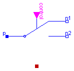
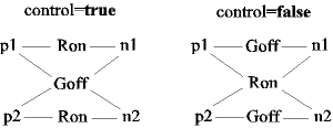
The commuting switch has a positive pin p and two negative pins n1 and n2. The switching behaviour is controlled by the inpug signal control. If control is true, the pin p is connected with the negative pin n2. Otherwise, the pin p is connected to the negative pin n1.
In order to prevent singularities during switching, the opened
switch has a (very low) conductance Goff
and the closed switch has a (very low) resistance Ron.
The limiting case is also allowed, i.e., the resistance Ron of the
closed switch could be exactly zero and the conductance Goff of the
open switch could be also exactly zero. Note, there are circuits,
where a description with zero Ron or zero Goff is not possible.
Please note:
In case of useHeatPort=true the temperature dependence of the electrical
behavior is not modelled. The parameters are not temperature dependent.
Extends from Modelica.Electrical.Analog.Interfaces.ConditionalHeatPort (Partial model to include a conditional HeatPort in order to describe the power loss via a thermal network).
| Type | Name | Default | Description |
|---|---|---|---|
| Resistance | Ron | 1.E-5 | Closed switch resistance [Ohm] |
| Conductance | Goff | 1.E-5 | Opened switch conductance [S] |
| Boolean | useHeatPort | false | =true, if HeatPort is enabled |
| Temperature | T | 293.15 | Fixed device temperature if useHeatPort = false [K] |
| Type | Name | Description |
|---|---|---|
| HeatPort_a | heatPort | |
| PositivePin | p | |
| NegativePin | n2 | |
| NegativePin | n1 | |
| input BooleanInput | control | true => p--n2 connected, false => p--n1 connected |
model IdealCommutingSwitch "Ideal commuting switch"
  parameter SI.Resistance Ron(final min=0) = 1.E-5 "Closed switch resistance";
  parameter SI.Conductance Goff(final min=0) = 1.E-5
    "Opened switch conductance";
  extends Modelica.Electrical.Analog.Interfaces.ConditionalHeatPort(final T=293.15);
  Interfaces.PositivePin p;
  Interfaces.NegativePin n2;
  Interfaces.NegativePin n1;
  Modelica.Blocks.Interfaces.BooleanInput control
    "true => p--n2 connected, false => p--n1 connected";
protected
  Real s1(final unit="1");
  Real s2(final unit="1") "Auxiliary variables";
  constant Modelica.SIunits.Voltage unitVoltage= 1;
  constant Modelica.SIunits.Current unitCurrent= 1;
equation
  0 = p.i + n2.i + n1.i;

  p.v - n1.v = (s1*unitCurrent)*(if (control) then 1 else Ron);
  n1.i = -(s1*unitVoltage)*(if (control) then Goff else 1);
  p.v - n2.v = (s2*unitCurrent)*(if (control) then Ron else 1);
  n2.i = -(s2*unitVoltage)*(if (control) then 1 else Goff);
  LossPower = p.i * p.v + n1.i *n1.v + n2.i * n2.v;
end IdealCommutingSwitch;
 Modelica.Electrical.Analog.Ideal.IdealIntermediateSwitch
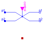
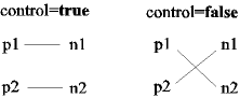
The intermediate switch has four switching contact pins p1, p2, n1, and n2. The switching behaviour is controlled by the input signal control. If control is true, the pin p1 is connected to pin n2, and the pin p2 is connected to the pin n2. Otherwise, the pin p1 is connected to n1, and p2 is connected to n2.
In order to prevent singularities during switching, the opened switch has a (very low) conductance Goff and the closed switch has a (very low) resistance Ron.
The limiting case is also allowed, i.e., the resistance Ron of the
closed switch could be exactly zero and the conductance Goff of the
open switch could be also exactly zero. Note, there are circuits,
where a description with zero Ron or zero Goff is not possible.
Please note:
In case of useHeatPort=true the temperature dependence of the electrical
behavior is not modelled. The parameters are not temperature dependent.
Extends from Modelica.Electrical.Analog.Interfaces.ConditionalHeatPort (Partial model to include a conditional HeatPort in order to describe the power loss via a thermal network).
| Type | Name | Default | Description |
|---|---|---|---|
| Resistance | Ron | 1.E-5 | Closed switch resistance [Ohm] |
| Conductance | Goff | 1.E-5 | Opened switch conductance [S] |
| Boolean | useHeatPort | false | =true, if HeatPort is enabled |
| Temperature | T | 293.15 | Fixed device temperature if useHeatPort = false [K] |
| Type | Name | Description |
|---|---|---|
| HeatPort_a | heatPort | |
| PositivePin | p1 | |
| PositivePin | p2 | |
| NegativePin | n1 | |
| NegativePin | n2 | |
| input BooleanInput | control | true => p1--n2, p2--n1 connected, otherwise p1--n1, p2--n2 connected |
model IdealIntermediateSwitch "Ideal intermediate switch"
  parameter SI.Resistance Ron(final min=0) = 1.E-5 "Closed switch resistance";
  parameter SI.Conductance Goff(final min=0) = 1.E-5
    "Opened switch conductance";
  extends Modelica.Electrical.Analog.Interfaces.ConditionalHeatPort(final T=293.15);
  Interfaces.PositivePin p1;
  Interfaces.PositivePin p2;
  Interfaces.NegativePin n1;
  Interfaces.NegativePin n2;
  Modelica.Blocks.Interfaces.BooleanInput control
    "true => p1--n2, p2--n1 connected, otherwise p1--n1, p2--n2  connected";
protected
  Real s1(final unit="1");
  Real s2(final unit="1");
  Real s3(final unit="1");
  Real s4(final unit="1") "Auxiliary variables";
  constant Modelica.SIunits.Voltage unitVoltage= 1;
  constant Modelica.SIunits.Current unitCurrent= 1;
equation
  p1.v - n1.v = (s1*unitCurrent)*(if (control) then 1 else Ron);
  p2.v - n2.v = (s2*unitCurrent)*(if (control) then 1 else Ron);
  p1.v - n2.v = (s3*unitCurrent)*(if (control) then Ron else 1);
  p2.v - n1.v = (s4*unitCurrent)*(if (control) then Ron else 1);

  p1.i = if control then s1*unitVoltage*Goff + s3*unitCurrent else s1*unitCurrent + s3*unitVoltage*Goff;
  p2.i = if control then s2*unitVoltage*Goff + s4*unitCurrent else s2*unitCurrent + s4*unitVoltage*Goff;
  n1.i = if control then -s1*unitVoltage*Goff - s4*unitCurrent else -s1*unitCurrent - s4*unitVoltage*Goff;
  n2.i = if control then -s2*unitVoltage*Goff - s3*unitCurrent else -s2*unitCurrent - s3*unitVoltage*Goff;

  LossPower = p1.i * p1.v + p2.i * p2.v + n1.i *n1.v + n2.i * n2.v;
end IdealIntermediateSwitch;
 Modelica.Electrical.Analog.Ideal.ControlledIdealCommutingSwitch
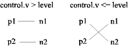
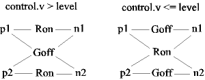
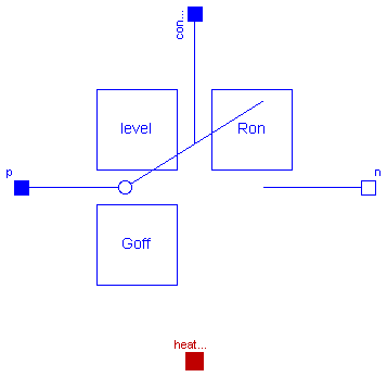
The commuting switch has a positive pin p and two negative pins n1 and n2. The switching behaviour is controlled by the control pin. If its voltage exceeds the value of the parameter level, the pin p is connected with the negative pin n2. Otherwise, the pin p is connected the negative pin n1.
In order to prevent singularities during switching, the opened
switch has a (very low) conductance Goff
and the closed switch has a (very low) resistance Ron.
The limiting case is also allowed, i.e., the resistance Ron of the
closed switch could be exactly zero and the conductance Goff of the
open switch could be also exactly zero. Note, there are circuits,
where a description with zero Ron or zero Goff is not possible.
Please note:
In case of useHeatPort=true the temperature dependence of the electrical
behavior is not modelled. The parameters are not temperature dependent.
Extends from Modelica.Electrical.Analog.Interfaces.ConditionalHeatPort (Partial model to include a conditional HeatPort in order to describe the power loss via a thermal network).
| Type | Name | Default | Description |
|---|---|---|---|
| Voltage | level | 0.5 | Switch level [V] |
| Resistance | Ron | 1.E-5 | Closed switch resistance [Ohm] |
| Conductance | Goff | 1.E-5 | Opened switch conductance [S] |
| Boolean | useHeatPort | false | =true, if HeatPort is enabled |
| Temperature | T | 293.15 | Fixed device temperature if useHeatPort = false [K] |
| Type | Name | Description |
|---|---|---|
| HeatPort_a | heatPort | |
| PositivePin | p | |
| NegativePin | n2 | |
| NegativePin | n1 | |
| Pin | control | Control pin: if control.v > level p--n2 connected, otherwise p--n1 connected |
model ControlledIdealCommutingSwitch
  "Controlled ideal commuting switch"
  parameter SI.Voltage level=0.5 "Switch level";
  parameter SI.Resistance Ron(final min=0) = 1.E-5 "Closed switch resistance";
  parameter SI.Conductance Goff(final min=0) = 1.E-5
    "Opened switch conductance";
  extends Modelica.Electrical.Analog.Interfaces.ConditionalHeatPort(final T=293.15);
  Interfaces.PositivePin p;
  Interfaces.NegativePin n2;
  Interfaces.NegativePin n1;
  Interfaces.Pin control
    "Control pin: if control.v > level p--n2 connected, otherwise p--n1 connected";
protected
  Real s1(final unit="1");
  Real s2(final unit="1") "Auxiliary variables";
  constant Modelica.SIunits.Voltage unitVoltage= 1;
  constant Modelica.SIunits.Current unitCurrent= 1;
equation
  control.i = 0;
  0 = p.i + n2.i + n1.i;

  p.v - n1.v = (s1*unitCurrent)*(if (control.v > level) then 1 else Ron);
  n1.i = -(s1*unitVoltage)*(if (control.v > level) then Goff else 1);
  p.v - n2.v = (s2*unitCurrent)*(if (control.v > level) then Ron else 1);
  n2.i = -(s2*unitVoltage)*(if (control.v > level) then 1 else Goff);
  LossPower = p.i * p.v + n1.i *n1.v + n2.i * n2.v;
end ControlledIdealCommutingSwitch;
 Modelica.Electrical.Analog.Ideal.ControlledIdealIntermediateSwitch
The intermediate switch has four switching contact pins p1, p2, n1, and n2. The switching behaviour is controlled by the control pin. If its voltage exceeds the value of the parameter level, the pin p1 is connected to pin n2, and the pin p2 is connected to the pin n2. Otherwise, the pin p1 is connected to n1, and p2 is connected to n2.
In order to prevent singularities during switching, the opened switch has a (very low) conductance Goff and the closed switch has a (very low) resistance Ron.
The limiting case is also allowed, i.e., the resistance Ron of the
closed switch could be exactly zero and the conductance Goff of the
open switch could be also exactly zero. Note, there are circuits,
where a description with zero Ron or zero Goff is not possible.
Please note:
In case of useHeatPort=true the temperature dependence of the electrical
behavior is not modelled. The parameters are not temperature dependent.
Extends from Modelica.Electrical.Analog.Interfaces.ConditionalHeatPort (Partial model to include a conditional HeatPort in order to describe the power loss via a thermal network).
| Type | Name | Default | Description |
|---|---|---|---|
| Voltage | level | 0.5 | Switch level [V] |
| Resistance | Ron | 1.E-5 | Closed switch resistance [Ohm] |
| Conductance | Goff | 1.E-5 | Opened switch conductance [S] |
| Boolean | useHeatPort | false | =true, if HeatPort is enabled |
| Temperature | T | 293.15 | Fixed device temperature if useHeatPort = false [K] |
| Type | Name | Description |
|---|---|---|
| HeatPort_a | heatPort | |
| PositivePin | p1 | |
| PositivePin | p2 | |
| NegativePin | n1 | |
| NegativePin | n2 | |
| Pin | control | Control pin: if control.v > level p1--n2, p2--n1 connected, otherwise p1--n1, p2--n2 connected |
model ControlledIdealIntermediateSwitch
  "Controlled ideal intermediate switch"
  parameter SI.Voltage level=0.5 "Switch level";
  parameter SI.Resistance Ron(final min=0) = 1.E-5 "Closed switch resistance";
  parameter SI.Conductance Goff(final min=0) = 1.E-5
    "Opened switch conductance";
  extends Modelica.Electrical.Analog.Interfaces.ConditionalHeatPort(final T=293.15);
  Interfaces.PositivePin p1;
  Interfaces.PositivePin p2;
  Interfaces.NegativePin n1;
  Interfaces.NegativePin n2;
  Interfaces.Pin control "Control pin: if control.v > level p1--n2, p2--n1 connected,
         otherwise p1--n1, p2--n2  connected";
protected
  Real s1(final unit="1");
  Real s2(final unit="1");
  Real s3(final unit="1");
  Real s4(final unit="1") "Auxiliary variables";
  constant Modelica.SIunits.Voltage unitVoltage= 1;
  constant Modelica.SIunits.Current unitCurrent= 1;
equation
  control.i = 0;

  p1.v - n1.v = (s1*unitCurrent)*(if (control.v > level) then 1 else Ron);
  p2.v - n2.v = (s2*unitCurrent)*(if (control.v > level) then 1 else Ron);
  p1.v - n2.v = (s3*unitCurrent)*(if (control.v > level) then Ron else 1);
  p2.v - n1.v = (s4*unitCurrent)*(if (control.v > level) then Ron else 1);

  p1.i = if control.v > level then s1*unitVoltage*Goff + s3*unitCurrent else s1*unitCurrent + s3*unitVoltage*Goff;
  p2.i = if control.v > level then s2*unitVoltage*Goff + s4*unitCurrent else s2*unitCurrent + s4*unitVoltage*Goff;
  n1.i = if control.v > level then -s1*unitVoltage*Goff - s4*unitCurrent else -s1*unitCurrent - s4*unitVoltage*Goff;
  n2.i = if control.v > level then -s2*unitVoltage*Goff - s3*unitCurrent else -s2*unitCurrent - s3*unitVoltage*Goff;

  LossPower = p1.i * p1.v + p2.i * p2.v + n1.i *n1.v + n2.i * n2.v;
end ControlledIdealIntermediateSwitch;
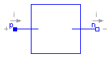
 Modelica.Electrical.Analog.Ideal.IdealOpAmp
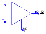
The ideal OpAmp is a two-port. The left port is fixed to v1=0 and i1=0 (nullator). At the right port both any voltage v2 and any current i2 are possible (norator).
| Type | Name | Description |
|---|---|---|
| PositivePin | p1 | Positive pin of the left port |
| NegativePin | n1 | Negative pin of the left port |
| PositivePin | p2 | Positive pin of the right port |
| NegativePin | n2 | Negative pin of the right port |
model IdealOpAmp "Ideal operational amplifier (norator-nullator pair)" SI.Voltage v1 "Voltage drop over the left port"; SI.Voltage v2 "Voltage drop over the right port"; SI.Current i1 "Current flowing from pos. to neg. pin of the left port"; SI.Current i2 "Current flowing from pos. to neg. pin of the right port";Interfaces.PositivePin p1 "Positive pin of the left port"; Interfaces.NegativePin n1 "Negative pin of the left port"; Interfaces.PositivePin p2 "Positive pin of the right port"; Interfaces.NegativePin n2 "Negative pin of the right port"; equation v1 = p1.v - n1.v; v2 = p2.v - n2.v; 0 = p1.i + n1.i; 0 = p2.i + n2.i; i1 = p1.i; i2 = p2.i; v1 = 0; i1 = 0;end IdealOpAmp;
 Modelica.Electrical.Analog.Ideal.IdealOpAmp3Pin
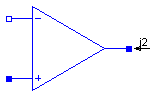
The ideal OpAmp with three pins is of exactly the same behaviour as the ideal OpAmp with four pins. Only the negative output pin is left out. Both the input voltage and current are fixed to zero (nullator). At the output pin both any voltage v2 and any current i2 are possible.
| Type | Name | Description |
|---|---|---|
| PositivePin | in_p | Positive pin of the input port |
| NegativePin | in_n | Negative pin of the input port |
| PositivePin | out | Output pin |
model IdealOpAmp3Pin "Ideal operational amplifier (norator-nullator pair), but 3 pins"Interfaces.PositivePin in_p "Positive pin of the input port"; Interfaces.NegativePin in_n "Negative pin of the input port"; Interfaces.PositivePin out "Output pin"; equation in_p.v = in_n.v; in_p.i = 0; in_n.i = 0;end IdealOpAmp3Pin;
 Modelica.Electrical.Analog.Ideal.IdealOpAmpLimited
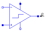
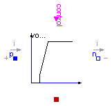
The ideal OpAmp with limitation behaves like an ideal OpAmp without limitation, if the output voltage is within the limits (VMin < out.v < VMax). In this case the input voltage vin=in_p.v - in_n.v is zero. If the input voltage is vin < 0, the output voltage is out.v = VMin. If the input voltage is vin > 0, the output voltage is out.v = VMax.
| Type | Name | Description |
|---|---|---|
| PositivePin | in_p | Positive pin of the input port |
| NegativePin | in_n | Negative pin of the input port |
| PositivePin | out | Output pin |
| PositivePin | VMax | Positive output voltage limitation |
| NegativePin | VMin | Negative output voltage limitation |
model IdealOpAmpLimited "Ideal operational amplifier with limitation"Interfaces.PositivePin in_p "Positive pin of the input port"; Interfaces.NegativePin in_n "Negative pin of the input port"; Interfaces.PositivePin out "Output pin"; Interfaces.PositivePin VMax "Positive output voltage limitation"; Interfaces.NegativePin VMin "Negative output voltage limitation"; SI.Voltage vin "input voltage"; protected Real s(final unit="1") "Auxiliary variable"; constant Modelica.SIunits.Voltage unitVoltage= 1; equation in_p.i = 0; in_n.i = 0; VMax.i = 0; VMin.i = 0; vin = in_p.v - in_n.v; in_p.v - in_n.v = unitVoltage*smooth(0,(if s < -1 then s + 1 else if s > 1 then s - 1 else 0)); out.v = smooth(0,if s < -1 then VMin.v else if s > 1 then VMax.v else (VMax.v - VMin.v)*s/2 + (VMax.v + VMin.v)/2);end IdealOpAmpLimited;
 Modelica.Electrical.Analog.Ideal.IdealDiode
This is an ideal switch which is
open (off), if it is reversed biased (voltage drop less than 0)
closed (on), if it is conducting (current > 0).
This is the behaviour if all parameters are exactly zero.
Note, there are circuits, where this ideal description
with zero resistance and zero cinductance is not possible.
In order to prevent singularities during switching, the opened
diode has a small conductance Gon and the closed diode has a low
resistance Roff which is default.
The parameter Vknee which is the forward threshold voltage, allows to displace
the knee point
along the Gon-characteristic until v = Vknee.
Please note:
In case of useHeatPort=true the temperature dependence of the electrical
behavior is not modelled.
Extends from Modelica.Electrical.Analog.Interfaces.OnePort (Component with two electrical pins p and n and current i from p to n), Modelica.Electrical.Analog.Interfaces.ConditionalHeatPort (Partial model to include a conditional HeatPort in order to describe the power loss via a thermal network).
| Type | Name | Default | Description |
|---|---|---|---|
| Resistance | Ron | 1.E-5 | Forward state-on differential resistance (closed diode resistance) [Ohm] |
| Conductance | Goff | 1.E-5 | Backward state-off conductance (opened diode conductance) [S] |
| Voltage | Vknee | Forward threshold voltage [V] | |
| Boolean | useHeatPort | false | =true, if HeatPort is enabled |
| Temperature | T | 293.15 | Fixed device temperature if useHeatPort = false [K] |
| Type | Name | Description |
|---|---|---|
| PositivePin | p | Positive pin (potential p.v > n.v for positive voltage drop v) |
| NegativePin | n | Negative pin |
| HeatPort_a | heatPort |
model IdealDiode "Ideal diode"
  extends Modelica.Electrical.Analog.Interfaces.OnePort;
  parameter Modelica.SIunits.Resistance Ron(final min=0) = 1.E-5
    "Forward state-on differential resistance (closed diode resistance)";
  parameter Modelica.SIunits.Conductance Goff(final min=0) = 1.E-5
    "Backward state-off conductance (opened diode conductance)";
  parameter Modelica.SIunits.Voltage Vknee(final min=0, start=0)
    "Forward threshold voltage";
  extends Modelica.Electrical.Analog.Interfaces.ConditionalHeatPort;
  Boolean off(start=true) "Switching state";
protected
  Real s(final unit="1")
    "Auxiliary variable: if on then current, if opened then voltage";
  constant Modelica.SIunits.Voltage unitVoltage= 1;
  constant Modelica.SIunits.Current unitCurrent= 1;
equation
  off = s < 0;
  v = (s*unitCurrent)*(if off then 1 else Ron) + Vknee;
  i = (s*unitVoltage)*(if off then Goff else 1) + Goff*Vknee;

  LossPower = v*i;
end IdealDiode;
 Modelica.Electrical.Analog.Ideal.IdealTransformer
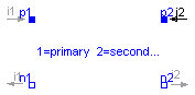
The ideal transformer is a two-port circuit element;
in case of Boolean parameter considerMagnetization = false it is characterized by the following equations:
 i2 = -i1*n;
 v2 =  v1/n;
where n is a real number called the turns ratio.
Due to this equations, also DC voltages and currents are transformed - which is not the case for technical transformers.
In case of Boolean parameter considerMagnetization = true it is characterized by the following equations:
 im1  = i1 + i2/n "Magnetizing current w.r.t. primary side";
 psim1= Lm1*im1   "Magnetic flux w.r.t. primary side";
 v1 = der(psim1)  "Primary voltage";
 v2 = v1/n        "Secondary voltage";
where Lm denotes the magnetizing inductance.
Due to this equations, the DC offset of secondary voltages and currents decrement according to the time constant defined by the connected circuit.
Taking primary L1sigma and secondary L2ssigma leakage inductances into account,
compared with the basic transformer
the following parameter conversion can be applied (which leads to identical results):
  L1 = L1sigma + M*n "Primary inductance at secondary no-load";
  L2 = L2sigma + M/n "Secondary inductance at primary no-load";
  M  = Lm1/n         "Mutual inductance";
For the backward conversion, one has to decide about the partitioning of the leakage to primary and secondary side.
Extends from Modelica.Electrical.Analog.Interfaces.TwoPort (Component with two electrical ports, including current).
| Type | Name | Default | Description |
|---|---|---|---|
| Real | n | Turns ratio primary:secondary voltage | |
| Boolean | considerMagnetization | false | |
| Inductance | Lm1 | Magnetization inductance w.r.t. primary side [H] |
| Type | Name | Description |
|---|---|---|
| PositivePin | p1 | Positive pin of the left port (potential p1.v > n1.v for positive voltage drop v1) |
| NegativePin | n1 | Negative pin of the left port |
| PositivePin | p2 | Positive pin of the right port (potential p2.v > n2.v for positive voltage drop v2) |
| NegativePin | n2 | Negative pin of the right port |
model IdealTransformer
  "Ideal transformer core with or without magnetization"
  extends Modelica.Electrical.Analog.Interfaces.TwoPort;
  parameter Real n(start=1) "Turns ratio primary:secondary voltage";
  parameter Boolean considerMagnetization=false;
  parameter Modelica.SIunits.Inductance Lm1(start=1)
    "Magnetization inductance w.r.t. primary side";
protected
  Modelica.SIunits.Current im1 "Magnetization current w.r.t. primary side";
  Modelica.SIunits.MagneticFlux psim1 "Magnetic flux w.r.t primary side";
equation
  im1 = i1 + i2/n;
  if considerMagnetization then
    psim1 = Lm1*im1;
    v1 = der(psim1);
  else
    psim1= 0;
    im1 = 0;
  end if;
  v1 =  n*v2;
end IdealTransformer;
 Modelica.Electrical.Analog.Ideal.IdealGyrator
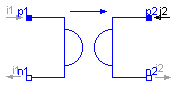
A gyrator is an ideal two-port element defined by the following equations:
    i1 =  G * v2
    i2 = -G * v1
where the constant G is called the gyration conductance.
Extends from Interfaces.TwoPort (Component with two electrical ports, including current).
| Type | Name | Default | Description |
|---|---|---|---|
| Conductance | G | Gyration conductance [S] |
| Type | Name | Description |
|---|---|---|
| PositivePin | p1 | Positive pin of the left port (potential p1.v > n1.v for positive voltage drop v1) |
| NegativePin | n1 | Negative pin of the left port |
| PositivePin | p2 | Positive pin of the right port (potential p2.v > n2.v for positive voltage drop v2) |
| NegativePin | n2 | Negative pin of the right port |
model IdealGyrator "Ideal gyrator" extends Interfaces.TwoPort; parameter SI.Conductance G(start=1) "Gyration conductance"; equation i1 = G*v2; i2 = -G*v1;end IdealGyrator;
 Modelica.Electrical.Analog.Ideal.Idle
The model Idle is a simple idle running branch.
Extends from Interfaces.OnePort (Component with two electrical pins p and n and current i from p to n).
| Type | Name | Description |
|---|---|---|
| PositivePin | p | Positive pin (potential p.v > n.v for positive voltage drop v) |
| NegativePin | n | Negative pin |
model Idle "Idle branch" extends Interfaces.OnePort; equation i = 0;end Idle;
 Modelica.Electrical.Analog.Ideal.Short
The model Short is a simple short cut branch.
Extends from Interfaces.OnePort (Component with two electrical pins p and n and current i from p to n).
| Type | Name | Description |
|---|---|---|
| PositivePin | p | Positive pin (potential p.v > n.v for positive voltage drop v) |
| NegativePin | n | Negative pin |
model Short "Short cut branch" extends Interfaces.OnePort; equation v = 0;end Short;
 Modelica.Electrical.Analog.Ideal.IdealOpeningSwitch
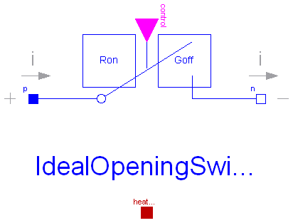
The ideal opening switch has a positive pin p and a negative pin n. The switching behaviour is controlled by the input signal control. If control is true, pin p is not connected with negative pin n. Otherwise, pin p is connected with negative pin n.
In order to prevent singularities during switching, the opened
switch has a (very low) conductance Goff
and the closed switch has a (very low) resistance Ron.
The limiting case is also allowed, i.e., the resistance Ron of the
closed switch could be exactly zero and the conductance Goff of the
open switch could be also exactly zero. Note, there are circuits,
where a description with zero Ron or zero Goff is not possible.
Please note:
In case of useHeatPort=true the temperature dependence of the electrical
behavior is not modelled. The parameters are not temperature dependent.
Extends from Modelica.Electrical.Analog.Interfaces.OnePort (Component with two electrical pins p and n and current i from p to n), Modelica.Electrical.Analog.Interfaces.ConditionalHeatPort (Partial model to include a conditional HeatPort in order to describe the power loss via a thermal network).
| Type | Name | Default | Description |
|---|---|---|---|
| Resistance | Ron | 1.E-5 | Closed switch resistance [Ohm] |
| Conductance | Goff | 1.E-5 | Opened switch conductance [S] |
| Boolean | useHeatPort | false | =true, if HeatPort is enabled |
| Temperature | T | 293.15 | Fixed device temperature if useHeatPort = false [K] |
| Type | Name | Description |
|---|---|---|
| PositivePin | p | Positive pin (potential p.v > n.v for positive voltage drop v) |
| NegativePin | n | Negative pin |
| HeatPort_a | heatPort | |
| input BooleanInput | control | true => switch open, false => p--n connected |
model IdealOpeningSwitch "Ideal electrical opener" extends Modelica.Electrical.Analog.Interfaces.OnePort;parameter SI.Resistance Ron(final min=0) = 1.E-5 "Closed switch resistance"; parameter SI.Conductance Goff(final min=0) = 1.E-5 "Opened switch conductance"; extends Modelica.Electrical.Analog.Interfaces.ConditionalHeatPort(final T=293.15);Modelica.Blocks.Interfaces.BooleanInput control "true => switch open, false => p--n connected"; protected Real s(final unit="1") "Auxiliary variable"; constant Modelica.SIunits.Voltage unitVoltage= 1; constant Modelica.SIunits.Current unitCurrent= 1; equation v = (s*unitCurrent)*(if control then 1 else Ron); i = (s*unitVoltage)*(if control then Goff else 1); LossPower = v*i;end IdealOpeningSwitch;
 Modelica.Electrical.Analog.Ideal.IdealClosingSwitch
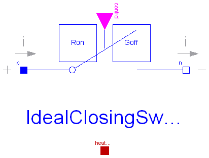
The ideal closing switch has a positive pin p and a negative pin n. The switching behaviour is controlled by input signal control. If control is true, pin p is connected with negative pin n. Otherwise, pin p is not connected with negative pin n.
In order to prevent singularities during switching, the opened
switch has a (very low) conductance Goff
and the closed switch has a (very low) resistance Ron.
The limiting case is also allowed, i.e., the resistance Ron of the
closed switch could be exactly zero and the conductance Goff of the
open switch could be also exactly zero. Note, there are circuits,
where a description with zero Ron or zero Goff is not possible.
Please note:
In case of useHeatPort=true the temperature dependence of the electrical
behavior is not modelled. The parameters are not temperature dependent.
Extends from Modelica.Electrical.Analog.Interfaces.OnePort (Component with two electrical pins p and n and current i from p to n), Modelica.Electrical.Analog.Interfaces.ConditionalHeatPort (Partial model to include a conditional HeatPort in order to describe the power loss via a thermal network).
| Type | Name | Default | Description |
|---|---|---|---|
| Resistance | Ron | 1.E-5 | Closed switch resistance [Ohm] |
| Conductance | Goff | 1.E-5 | Opened switch conductance [S] |
| Boolean | useHeatPort | false | =true, if HeatPort is enabled |
| Temperature | T | 293.15 | Fixed device temperature if useHeatPort = false [K] |
| Type | Name | Description |
|---|---|---|
| PositivePin | p | Positive pin (potential p.v > n.v for positive voltage drop v) |
| NegativePin | n | Negative pin |
| HeatPort_a | heatPort | |
| input BooleanInput | control | true => p--n connected, false => switch open |
model IdealClosingSwitch "Ideal electrical closer" extends Modelica.Electrical.Analog.Interfaces.OnePort;parameter SI.Resistance Ron(final min=0) = 1.E-5 "Closed switch resistance"; parameter SI.Conductance Goff(final min=0) = 1.E-5 "Opened switch conductance"; extends Modelica.Electrical.Analog.Interfaces.ConditionalHeatPort(final T=293.15);Modelica.Blocks.Interfaces.BooleanInput control "true => p--n connected, false => switch open"; protected Real s(final unit="1") "Auxiliary variable"; constant Modelica.SIunits.Voltage unitVoltage= 1; constant Modelica.SIunits.Current unitCurrent= 1; equation v = (s*unitCurrent)*(if control then Ron else 1); i = (s*unitVoltage)*(if control then 1 else Goff); LossPower = v*i;end IdealClosingSwitch;
 Modelica.Electrical.Analog.Ideal.ControlledIdealOpeningSwitch
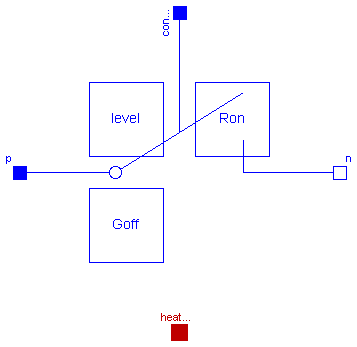
The ideal switch has a positive pin p and a negative pin n. The switching behaviour is controlled by the control pin. If its voltage exceeds the voltage of the parameter level, pin p is not connected with negative pin n. Otherwise, pin p is connected with negative pin n.
In order to prevent singularities during switching, the opened
switch has a (very low) conductance Goff
and the closed switch has a (very low) resistance Ron.
The limiting case is also allowed, i.e., the resistance Ron of the
closed switch could be exactly zero and the conductance Goff of the
open switch could be also exactly zero. Note, there are circuits,
where a description with zero Ron or zero Goff is not possible.
Please note:
In case of useHeatPort=true the temperature dependence of the electrical
behavior is not modelled. The parameters are not temperature dependent.
Extends from Modelica.Electrical.Analog.Interfaces.ConditionalHeatPort (Partial model to include a conditional HeatPort in order to describe the power loss via a thermal network).
| Type | Name | Default | Description |
|---|---|---|---|
| Voltage | level | 0.5 | Switch level [V] |
| Resistance | Ron | 1.E-5 | Closed switch resistance [Ohm] |
| Conductance | Goff | 1.E-5 | Opened switch conductance [S] |
| Boolean | useHeatPort | false | =true, if HeatPort is enabled |
| Temperature | T | 293.15 | Fixed device temperature if useHeatPort = false [K] |
| Type | Name | Description |
|---|---|---|
| HeatPort_a | heatPort | |
| PositivePin | p | |
| NegativePin | n | |
| Pin | control | Control pin: control.v > level switch open, otherwise p--n connected |
model ControlledIdealOpeningSwitch "Controlled ideal electrical opener"parameter SI.Voltage level=0.5 "Switch level"; parameter SI.Resistance Ron(final min=0) = 1.E-5 "Closed switch resistance"; parameter SI.Conductance Goff(final min=0) = 1.E-5 "Opened switch conductance"; extends Modelica.Electrical.Analog.Interfaces.ConditionalHeatPort(final T=293.15);Interfaces.PositivePin p; Interfaces.NegativePin n; Interfaces.Pin control "Control pin: control.v > level switch open, otherwise p--n connected"; protected Real s(final unit="1") "Auxiliary variable"; constant Modelica.SIunits.Voltage unitVoltage= 1; constant Modelica.SIunits.Current unitCurrent= 1; equation control.i = 0; 0 = p.i + n.i; p.v - n.v = (s*unitCurrent)*(if (control.v > level) then 1 else Ron); p.i = (s*unitVoltage)*(if (control.v > level) then Goff else 1); LossPower = (p.v - n.v)*p.i;end ControlledIdealOpeningSwitch;
 Modelica.Electrical.Analog.Ideal.ControlledIdealClosingSwitch
The closing ideal switch has a positive pin p and a negative pin n. The switching behaviour is controlled by the control pin. If its voltage exceeds the voltage of the parameter level, pin p is connected with negative pin n. Otherwise, pin p is not connected with negative pin n.
In order to prevent singularities during switching, the opened
switch has a (very low) conductance Goff
and the closed switch has a (very low) resistance Ron.
The limiting case is also allowed, i.e., the resistance Ron of the
closed switch could be exactly zero and the conductance Goff of the
open switch could be also exactly zero. Note, there are circuits,
where a description with zero Ron or zero Goff is not possible.
Please note:
In case of useHeatPort=true the temperature dependence of the electrical
behavior is not modelled. The parameters are not temperature dependent.
Extends from Modelica.Electrical.Analog.Interfaces.ConditionalHeatPort (Partial model to include a conditional HeatPort in order to describe the power loss via a thermal network).
| Type | Name | Default | Description |
|---|---|---|---|
| Voltage | level | 0.5 | Switch level [V] |
| Resistance | Ron | 1.E-5 | Closed switch resistance [Ohm] |
| Conductance | Goff | 1.E-5 | Opened switch conductance [S] |
| Boolean | useHeatPort | false | =true, if HeatPort is enabled |
| Temperature | T | 293.15 | Fixed device temperature if useHeatPort = false [K] |
| Type | Name | Description |
|---|---|---|
| HeatPort_a | heatPort | |
| PositivePin | p | |
| NegativePin | n | |
| Pin | control | Control pin: control.v > level switch closed, otherwise switch open |
model ControlledIdealClosingSwitch "Controlled ideal electrical closer"parameter SI.Voltage level=0.5 "Switch level"; parameter SI.Resistance Ron(final min=0) = 1.E-5 "Closed switch resistance"; parameter SI.Conductance Goff(final min=0) = 1.E-5 "Opened switch conductance"; extends Modelica.Electrical.Analog.Interfaces.ConditionalHeatPort(final T=293.15);Modelica.Electrical.Analog.Interfaces.PositivePin p; Modelica.Electrical.Analog.Interfaces.NegativePin n; Modelica.Electrical.Analog.Interfaces.Pin control "Control pin: control.v > level switch closed, otherwise switch open"; protected Real s(final unit="1") "Auxiliary variable"; constant Modelica.SIunits.Voltage unitVoltage= 1; constant Modelica.SIunits.Current unitCurrent= 1; equation control.i = 0; 0 = p.i + n.i; p.v - n.v = (s*unitCurrent)*(if (control.v > level) then Ron else 1); p.i = (s*unitVoltage)*(if (control.v > level) then 1 else Goff); LossPower = (p.v - n.v)*p.i;end ControlledIdealClosingSwitch;
 Modelica.Electrical.Analog.Ideal.OpenerWithArc
This model is an extension to the IdealOpeningSwitch.
The basic model interupts the current through the switch in an infinitesimal time span. If an inductive circuit is connected, the voltage across the swicth is limited only by numerics. In order to give a better idea for the voltage across the switch, a simple arc model is added:
When the Boolean input control signals to open the switch, a voltage across the opened switch is impressed.
This voltage starts with V0 (simulating the voltage drop of the arc roots), then rising with slope dVdt
(simulating the rising voltage of an extending arc) until a maximum voltage Vmax is reached.
     | voltage
Vmax |      +-----
     |     /
     |    /
V0   |   +
     |   |
     +---+-------- time
This arc voltage tends to lower the current following through the switch; it depends on the connected circuit, when the arc is quenched.
Once the arc is quenched, i.e. the current flowing through the switch gets zero, the equation for the off-state is activated
i=Goff*v.
When the Boolean input control signals to close the switch again, the switch is closed immediately,
i.e. the equation for the on-state is activated v=Ron*i.
Please note: In an AC circuit, at least the arc quenches when the next natural zero-crossing of the current occurs.
In a DC circuit, the arc will not quench if the arc voltage is not sufficient that a zero-crossing of the current occurs.
Please note:
In case of useHeatPort=true the temperature dependence of the electrical
behavior is not modelled. The parameters are not temperature dependent.
Extends from Modelica.Electrical.Analog.Interfaces.OnePort (Component with two electrical pins p and n and current i from p to n), Modelica.Electrical.Analog.Interfaces.ConditionalHeatPort (Partial model to include a conditional HeatPort in order to describe the power loss via a thermal network).
| Type | Name | Default | Description |
|---|---|---|---|
| Resistance | Ron | 1E-5 | Closed switch resistance [Ohm] |
| Conductance | Goff | 1E-5 | Opened switch conductance [S] |
| Voltage | V0 | 30 | Initial arc voltage [V] |
| VoltageSlope | dVdt | 10E3 | Arc voltage slope [V/s] |
| Voltage | Vmax | 60 | Max. arc voltage [V] |
| Boolean | useHeatPort | false | =true, if HeatPort is enabled |
| Temperature | T | 293.15 | Fixed device temperature if useHeatPort = false [K] |
| Type | Name | Description |
|---|---|---|
| PositivePin | p | Positive pin (potential p.v > n.v for positive voltage drop v) |
| NegativePin | n | Negative pin |
| HeatPort_a | heatPort | |
| input BooleanInput | control | false => p--n connected, true => switch open |
model OpenerWithArc "Ideal opening switch with simple arc model" extends Modelica.Electrical.Analog.Interfaces.OnePort; parameter Modelica.SIunits.Resistance Ron= 1E-5 "Closed switch resistance"; parameter Modelica.SIunits.Conductance Goff=1E-5 "Opened switch conductance"; parameter Modelica.SIunits.Voltage V0=30 "Initial arc voltage"; parameter Modelica.SIunits.VoltageSlope dVdt=10E3 "Arc voltage slope"; parameter Modelica.SIunits.Voltage Vmax=60 "Max. arc voltage"; extends Modelica.Electrical.Analog.Interfaces.ConditionalHeatPort(final T=293.15);Modelica.Blocks.Interfaces.BooleanInput control "false => p--n connected, true => switch open"; protected Boolean off=control; Boolean on=not off; discrete Modelica.SIunits.Time tSwitch; Boolean quenched; equation when edge(off) then tSwitch=time; end when; quenched=off and (abs(i)<=abs(v)*Goff or pre(quenched)); if on then v=Ron*i; else if quenched then i=Goff*v; else v=min(Vmax, V0 + dVdt*(time - tSwitch))*sign(i); end if; end if; LossPower = v*i;end OpenerWithArc;
 Modelica.Electrical.Analog.Ideal.CloserWithArc
This model is an extension to the IdealClosingSwitch.
The basic model interupts the current through the switch in an infinitesimal time span. If an inductive circuit is connected, the voltage across the swicth is limited only by numerics. In order to give a better idea for the voltage across the switch, a simple arc model is added:
When the Boolean input control signals to open the switch, a voltage across the opened switch is impressed.
This voltage starts with V0 (simulating the voltage drop of the arc roots), then rising with slope dVdt
(simulating the rising voltage of an extending arc) until a maximum voltage Vmax is reached.
     | voltage
Vmax |      +-----
     |     /
     |    /
V0   |   +
     |   |
     +---+-------- time
This arc voltage tends to lower the current following through the switch; it depends on the connected circuit, when the arc is quenched.
Once the arc is quenched, i.e. the current flowing through the switch gets zero, the equation for the off-state is activated
i=Goff*v.
When the Boolean input control signals to close the switch again, the switch is closed immediately,
i.e. the equation for the on-state is activated v=Ron*i.
Please note: In an AC circuit, at least the arc quenches when the next natural zero-crossing of the current occurs.
In a DC circuit, the arc will not quench if the arc voltage is not sufficient that a zero-crossing of the current occurs.
Please note:
In case of useHeatPort=true the temperature dependence of the electrical
behavior is not modelled. The parameters are not temperature dependent.
Extends from Modelica.Electrical.Analog.Interfaces.OnePort (Component with two electrical pins p and n and current i from p to n), Modelica.Electrical.Analog.Interfaces.ConditionalHeatPort (Partial model to include a conditional HeatPort in order to describe the power loss via a thermal network).
| Type | Name | Default | Description |
|---|---|---|---|
| Resistance | Ron | 1E-5 | Closed switch resistance [Ohm] |
| Conductance | Goff | 1E-5 | Opened switch conductance [S] |
| Voltage | V0 | 30 | Initial arc voltage [V] |
| VoltageSlope | dVdt | 10E3 | Arc voltage slope [V/s] |
| Voltage | Vmax | 60 | Max. arc voltage [V] |
| Boolean | useHeatPort | false | =true, if HeatPort is enabled |
| Temperature | T | 293.15 | Fixed device temperature if useHeatPort = false [K] |
| Type | Name | Description |
|---|---|---|
| PositivePin | p | Positive pin (potential p.v > n.v for positive voltage drop v) |
| NegativePin | n | Negative pin |
| HeatPort_a | heatPort | |
| input BooleanInput | control | true => p--n connected, false => switch open |
model CloserWithArc "Ideal closing switch with simple arc model" extends Modelica.Electrical.Analog.Interfaces.OnePort; parameter Modelica.SIunits.Resistance Ron= 1E-5 "Closed switch resistance"; parameter Modelica.SIunits.Conductance Goff=1E-5 "Opened switch conductance"; parameter Modelica.SIunits.Voltage V0=30 "Initial arc voltage"; parameter Modelica.SIunits.VoltageSlope dVdt=10E3 "Arc voltage slope"; parameter Modelica.SIunits.Voltage Vmax=60 "Max. arc voltage"; extends Modelica.Electrical.Analog.Interfaces.ConditionalHeatPort(final T=293.15);Modelica.Blocks.Interfaces.BooleanInput control "true => p--n connected, false => switch open"; protected Boolean on=control; Boolean off=not on; discrete Modelica.SIunits.Time tSwitch; Boolean quenched; equation when edge(off) then tSwitch=time; end when; quenched=off and (abs(i)<=abs(v)*Goff or pre(quenched)); if on then v=Ron*i; else if quenched then i=Goff*v; else v=min(Vmax, V0 + dVdt*(time - tSwitch))*sign(i); end if; end if; LossPower = v*i;end CloserWithArc;
 Modelica.Electrical.Analog.Ideal.ControlledOpenerWithArc

This model is an extension to the IdealOpeningSwitch.
The basic model interupts the current through the switch in an infinitesimal time span. If an inductive circuit is connected, the voltage across the swicth is limited only by numerics. In order to give a better idea for the voltage across the switch, a simple arc model is added:
When the control pin voltage control.v signals to open the switch, a voltage across the opened switch is impressed.
This voltage starts with V0 (simulating the voltage drop of the arc roots), then rising with slope dVdt
(simulating the rising voltage of an extending arc) until a maximum voltage Vmax is reached.
     | voltage
Vmax |      +-----
     |     /
     |    /
V0   |   +
     |   |
     +---+-------- time
This arc voltage tends to lower the current following through the switch; it depends on the connected circuit, when the arc is quenched.
Once the arc is quenched, i.e. the current flowing through the switch gets zero, the equation for the off-state is activated
i=Goff*v.
When the control pin control.v signals to close the switch again, the switch is closed immediately,
i.e. the equation for the on-state is activated v=Ron*i.
Please note: In an AC circuit, at least the arc quenches when the next natural zero-crossing of the current occurs.
In a DC circuit, the arc will not quench if the arc voltage is not sufficient that a zero-crossing of the current occurs.
Please note:
In case of useHeatPort=true the temperature dependence of the electrical
behavior is not modelled. The parameters are not temperature dependent.
Extends from Modelica.Electrical.Analog.Interfaces.ConditionalHeatPort (Partial model to include a conditional HeatPort in order to describe the power loss via a thermal network).
| Type | Name | Default | Description |
|---|---|---|---|
| Voltage | level | 0.5 | Switch level [V] |
| Resistance | Ron | 1.E-5 | Closed switch resistance [Ohm] |
| Conductance | Goff | 1.E-5 | Opened switch conductance [S] |
| Voltage | V0 | 30 | Initial arc voltage [V] |
| VoltageSlope | dVdt | 10E3 | Arc voltage slope [V/s] |
| Voltage | Vmax | 60 | Max. arc voltage [V] |
| Boolean | useHeatPort | false | =true, if HeatPort is enabled |
| Temperature | T | 293.15 | Fixed device temperature if useHeatPort = false [K] |
| Type | Name | Description |
|---|---|---|
| HeatPort_a | heatPort | |
| PositivePin | p | |
| NegativePin | n | |
| Pin | control | Control pin: control.v > level switch open, otherwise p--n connected |
model ControlledOpenerWithArc "Controlled ideal electrical opener with simple arc model"parameter Modelica.SIunits.Voltage level=0.5 "Switch level"; parameter Modelica.SIunits.Resistance Ron(final min=0)=1.E-5 "Closed switch resistance"; parameter Modelica.SIunits.Conductance Goff(final min=0)=1.E-5 "Opened switch conductance"; parameter Modelica.SIunits.Voltage V0=30 "Initial arc voltage"; parameter Modelica.SIunits.VoltageSlope dVdt=10E3 "Arc voltage slope"; parameter Modelica.SIunits.Voltage Vmax=60 "Max. arc voltage"; extends Modelica.Electrical.Analog.Interfaces.ConditionalHeatPort(final T=293.15);Modelica.Electrical.Analog.Interfaces.PositivePin p; Modelica.Electrical.Analog.Interfaces.NegativePin n; Modelica.Electrical.Analog.Interfaces.Pin control "Control pin: control.v > level switch open, otherwise p--n connected"; Modelica.SIunits.Current i; Modelica.SIunits.Voltage v; protected constant Modelica.SIunits.Voltage unitVoltage= 1; constant Modelica.SIunits.Current unitCurrent= 1; Boolean off=(control.v > level); Boolean on=not off; discrete Modelica.SIunits.Time tSwitch; Boolean quenched; equation control.i = 0; 0 = p.i + n.i; i = p.i; p.v - n.v = v; when edge(off) then tSwitch=time; end when; quenched=off and (abs(i)<=abs(v)*Goff or pre(quenched)); if on then v=Ron*i; else if quenched then i=Goff*v; else v=min(Vmax, V0 + dVdt*(time - tSwitch))*sign(i); end if; end if; LossPower = v*i;end ControlledOpenerWithArc;
 Modelica.Electrical.Analog.Ideal.ControlledCloserWithArc

This model is an extension to the IdealClosingSwitch.
The basic model interupts the current through the switch in an infinitesimal time span. If an inductive circuit is connected, the voltage across the swicth is limited only by numerics. In order to give a better idea for the voltage across the switch, a simple arc model is added:
When the control pin voltage control.v signals to open the switch, a voltage across the opened switch is impressed.
This voltage starts with V0 (simulating the voltage drop of the arc roots), then rising with slope dVdt
(simulating the rising voltage of an extending arc) until a maximum voltage Vmax is reached.
     | voltage
Vmax |      +-----
     |     /
     |    /
V0   |   +
     |   |
     +---+-------- time
This arc voltage tends to lower the current following through the switch; it depends on the connected circuit, when the arc is quenched.
Once the arc is quenched, i.e. the current flowing through the switch gets zero, the equation for the off-state is activated
i=Goff*v.
When the control pin control.v signals to close the switch again, the switch is closed immediately,
i.e. the equation for the on-state is activated v=Ron*i.
Please note: In an AC circuit, at least the arc quenches when the next natural zero-crossing of the current occurs.
In a DC circuit, the arc will not quench if the arc voltage is not sufficient that a zero-crossing of the current occurs.
Please note:
In case of useHeatPort=true the temperature dependence of the electrical
behavior is not modelled. The parameters are not temperature dependent.
Extends from Modelica.Electrical.Analog.Interfaces.ConditionalHeatPort (Partial model to include a conditional HeatPort in order to describe the power loss via a thermal network).
| Type | Name | Default | Description |
|---|---|---|---|
| Voltage | level | 0.5 | Switch level [V] |
| Resistance | Ron | 1.E-5 | Closed switch resistance [Ohm] |
| Conductance | Goff | 1.E-5 | Opened switch conductance [S] |
| Voltage | V0 | 30 | Initial arc voltage [V] |
| VoltageSlope | dVdt | 10E3 | Arc voltage slope [V/s] |
| Voltage | Vmax | 60 | Max. arc voltage [V] |
| Boolean | useHeatPort | false | =true, if HeatPort is enabled |
| Temperature | T | 293.15 | Fixed device temperature if useHeatPort = false [K] |
| Type | Name | Description |
|---|---|---|
| HeatPort_a | heatPort | |
| PositivePin | p | |
| NegativePin | n | |
| Pin | control | Control pin: control.v > level switch closed, otherwise switch open |
model ControlledCloserWithArc "Controlled ideal electrical closer with simple arc model"parameter Modelica.SIunits.Voltage level=0.5 "Switch level"; parameter Modelica.SIunits.Resistance Ron(final min=0)=1.E-5 "Closed switch resistance"; parameter Modelica.SIunits.Conductance Goff(final min=0)=1.E-5 "Opened switch conductance"; parameter Modelica.SIunits.Voltage V0=30 "Initial arc voltage"; parameter Modelica.SIunits.VoltageSlope dVdt=10E3 "Arc voltage slope"; parameter Modelica.SIunits.Voltage Vmax=60 "Max. arc voltage"; extends Modelica.Electrical.Analog.Interfaces.ConditionalHeatPort(final T=293.15);Modelica.Electrical.Analog.Interfaces.PositivePin p; Modelica.Electrical.Analog.Interfaces.NegativePin n; Modelica.Electrical.Analog.Interfaces.Pin control "Control pin: control.v > level switch closed, otherwise switch open"; Modelica.SIunits.Current i; Modelica.SIunits.Voltage v; protected constant Modelica.SIunits.Voltage unitVoltage= 1; constant Modelica.SIunits.Current unitCurrent= 1; Boolean off=(control.v < level); Boolean on=not off; discrete Modelica.SIunits.Time tSwitch; Boolean quenched; equation control.i = 0; 0 = p.i + n.i; i = p.i; p.v - n.v = v; when edge(off) then tSwitch=time; end when; quenched=off and (abs(i)<=abs(v)*Goff or pre(quenched)); if on then v=Ron*i; else if quenched then i=Goff*v; else v=min(Vmax, V0 + dVdt*(time - tSwitch))*sign(i); end if; end if; LossPower = v*i;end ControlledCloserWithArc;