This package contains connectors and interfaces (partial models) for analog electrical components.
Extends from Modelica.Icons.Library (Icon for library).
| Name | Description |
|---|---|
| Pin of an electrical component | |
| Positive pin of an electric component | |
| Negative pin of an electric component | |
| Component with one electrical port | |
| Component with two electrical pins p and n and current i from p to n | |
| Component with two electrical ports, including current | |
| Partial model to include a conditional HeatPort in order to describe the power loss via a thermal network | |
| Base class to measure the absolute value of a pin variable | |
| Base class to measure a relative variable between two pins | |
| Interface for voltage sources | |
| Interface for current sources |
 Modelica.Electrical.Analog.Interfaces.Pin

| Type | Name | Description |
|---|---|---|
| Voltage | v | Potential at the pin [V] |
| flow Current | i | Current flowing into the pin [A] |
connector Pin "Pin of an electrical component" Modelica.SIunits.Voltage v "Potential at the pin"; flow Modelica.SIunits.Current i "Current flowing into the pin";end Pin;
Modelica.Electrical.Analog.Interfaces.PositivePin
Connectors PositivePin and NegativePin are nearly identical. The only difference is that the icons are different in order to identify more easily the pins of a component. Usually, connector PositivePin is used for the positive and connector NegativePin for the negative pin of an electrical component.
| Type | Name | Description |
|---|---|---|
| Voltage | v | Potential at the pin [V] |
| flow Current | i | Current flowing into the pin [A] |
connector PositivePin "Positive pin of an electric component" Modelica.SIunits.Voltage v "Potential at the pin"; flow Modelica.SIunits.Current i "Current flowing into the pin";end PositivePin;
 Modelica.Electrical.Analog.Interfaces.NegativePin
Connectors PositivePin and NegativePin are nearly identical. The only difference is that the icons are different in order to identify more easily the pins of a component. Usually, connector PositivePin is used for the positive and connector NegativePin for the negative pin of an electrical component.
| Type | Name | Description |
|---|---|---|
| Voltage | v | Potential at the pin [V] |
| flow Current | i | Current flowing into the pin [A] |
connector NegativePin "Negative pin of an electric component" Modelica.SIunits.Voltage v "Potential at the pin"; flow Modelica.SIunits.Current i "Current flowing into the pin";end NegativePin;
 Modelica.Electrical.Analog.Interfaces.TwoPin
| Type | Name | Description |
|---|---|---|
| PositivePin | p | Positive pin Positive pin (potential p.v > n.v for positive voltage drop v) |
| NegativePin | n | Negative pin |
partial model TwoPin "Component with one electrical port" SI.Voltage v "Voltage drop between the two pins (= p.v - n.v)";PositivePin p "Positive pin Positive pin (potential p.v > n.v for positive voltage drop v)"; NegativePin n "Negative pin"; equation v = p.v - n.v;end TwoPin;
Modelica.Electrical.Analog.Interfaces.OnePort
Superclass of elements which have two electrical pins: the positive pin connector p, and the negative pin connector n. It is assumed that the current flowing into pin p is identical to the current flowing out of pin n. This current is provided explicitly as current i.
| Type | Name | Description |
|---|---|---|
| PositivePin | p | Positive pin (potential p.v > n.v for positive voltage drop v) |
| NegativePin | n | Negative pin |
partial model OnePort "Component with two electrical pins p and n and current i from p to n" SI.Voltage v "Voltage drop between the two pins (= p.v - n.v)"; SI.Current i "Current flowing from pin p to pin n";PositivePin p "Positive pin (potential p.v > n.v for positive voltage drop v)"; NegativePin n "Negative pin"; equation v = p.v - n.v; 0 = p.i + n.i; i = p.i;end OnePort;
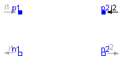
 Modelica.Electrical.Analog.Interfaces.TwoPort
| Type | Name | Description |
|---|---|---|
| PositivePin | p1 | Positive pin of the left port (potential p1.v > n1.v for positive voltage drop v1) |
| NegativePin | n1 | Negative pin of the left port |
| PositivePin | p2 | Positive pin of the right port (potential p2.v > n2.v for positive voltage drop v2) |
| NegativePin | n2 | Negative pin of the right port |
partial model TwoPort "Component with two electrical ports, including current" SI.Voltage v1 "Voltage drop over the left port"; SI.Voltage v2 "Voltage drop over the right port"; SI.Current i1 "Current flowing from pos. to neg. pin of the left port"; SI.Current i2 "Current flowing from pos. to neg. pin of the right port";PositivePin p1 "Positive pin of the left port (potential p1.v > n1.v for positive voltage drop v1)"; NegativePin n1 "Negative pin of the left port"; PositivePin p2 "Positive pin of the right port (potential p2.v > n2.v for positive voltage drop v2)"; NegativePin n2 "Negative pin of the right port"; equation v1 = p1.v - n1.v; v2 = p2.v - n2.v; 0 = p1.i + n1.i; 0 = p2.i + n2.i; i1 = p1.i; i2 = p2.i;end TwoPort;
 Modelica.Electrical.Analog.Interfaces.ConditionalHeatPort

This partial model provides a conditional heating port for the connection to a thermal network.
If this model is used, the loss power has to be provided by an equation in the model which inherits from ConditionalHeatingPort model (lossPower = ...). As device temperature T_heatPort can be used to describe the influence of the device temperature on the model behaviour.
| Type | Name | Default | Description |
|---|---|---|---|
| Boolean | useHeatPort | false | =true, if HeatPort is enabled |
| Temperature | T | 293.15 | Fixed device temperature if useHeatPort = false [K] |
| Type | Name | Description |
|---|---|---|
| HeatPort_a | heatPort |
partial model ConditionalHeatPort
  "Partial model to include a conditional HeatPort in order to describe the power loss via a thermal network"

  parameter Boolean useHeatPort = false "=true, if HeatPort is enabled";
  parameter Modelica.SIunits.Temperature T=293.15
    "Fixed device temperature if useHeatPort = false";
  Modelica.Thermal.HeatTransfer.Interfaces.HeatPort_a heatPort(T(start=T)=T_heatPort, Q_flow=-LossPower) if useHeatPort;
  Modelica.SIunits.Power LossPower "Loss power leaving component via HeatPort";
  Modelica.SIunits.Temperature T_heatPort "Temperature of HeatPort";
equation
  if not useHeatPort then
     T_heatPort = T;
  end if;

end ConditionalHeatPort;
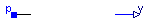
 Modelica.Electrical.Analog.Interfaces.AbsoluteSensor
| Type | Name | Description |
|---|---|---|
| PositivePin | p | Pin to be measured |
| output RealOutput | y | Measured quantity as Real output signal |
partial model AbsoluteSensor "Base class to measure the absolute value of a pin variable" extends Modelica.Icons.RotationalSensor;Interfaces.PositivePin p "Pin to be measured"; Modelica.Blocks.Interfaces.RealOutput y "Measured quantity as Real output signal"; end AbsoluteSensor;
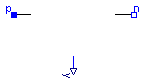
 Modelica.Electrical.Analog.Interfaces.RelativeSensor
| Type | Name | Description |
|---|---|---|
| PositivePin | p | Positive pin |
| NegativePin | n | Negative pin |
| output RealOutput | y | Measured quantity as Real output signal |
partial model RelativeSensor "Base class to measure a relative variable between two pins" extends Modelica.Icons.RotationalSensor;Interfaces.PositivePin p "Positive pin"; Interfaces.NegativePin n "Negative pin"; Modelica.Blocks.Interfaces.RealOutput y "Measured quantity as Real output signal"; end RelativeSensor;
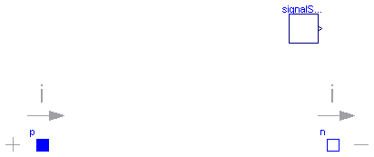
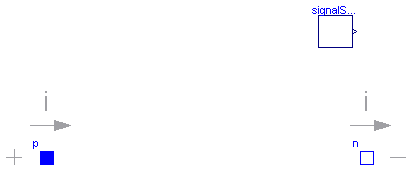
 Modelica.Electrical.Analog.Interfaces.VoltageSource
| Type | Name | Default | Description |
|---|---|---|---|
| Voltage | offset | 0 | Voltage offset [V] |
| Time | startTime | 0 | Time offset [s] |
| SignalSource | signalSource | redeclare Modelica.Blocks.In... |
| Type | Name | Description |
|---|---|---|
| PositivePin | p | Positive pin (potential p.v > n.v for positive voltage drop v) |
| NegativePin | n | Negative pin |
partial model VoltageSource "Interface for voltage sources" extends OnePort; parameter SI.Voltage offset=0 "Voltage offset"; parameter SI.Time startTime=0 "Time offset";replaceable Modelica.Blocks.Interfaces.SignalSource signalSource( final offset = offset, final startTime=startTime); equation v = signalSource.y;end VoltageSource;
 Modelica.Electrical.Analog.Interfaces.CurrentSource
| Type | Name | Default | Description |
|---|---|---|---|
| Current | offset | 0 | Current offset [A] |
| Time | startTime | 0 | Time offset [s] |
| SignalSource | signalSource | redeclare Modelica.Blocks.In... |
| Type | Name | Description |
|---|---|---|
| PositivePin | p | Positive pin (potential p.v > n.v for positive voltage drop v) |
| NegativePin | n | Negative pin |
partial model CurrentSource "Interface for current sources" extends OnePort; parameter SI.Current offset=0 "Current offset"; parameter SI.Time startTime=0 "Time offset";replaceable Modelica.Blocks.Interfaces.SignalSource signalSource( final offset = offset, final startTime=startTime); equation i = signalSource.y;end CurrentSource;