Buildings.Obsolete.Fluid.FixedResistances
Package with models for fixed flow resistances
Information
This package contains component models for fixed flow resistances.
Extends from Modelica.Icons.VariantsPackage (Icon for package containing variants).
Package Content
| Name | Description |
|---|---|
| Pipe model using spatialDistribution for temperature delay | |
 Buildings.Obsolete.Fluid.FixedResistances.PlugFlowPipe
Pipe model using spatialDistribution for temperature delay
Information
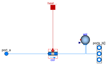
Pipe with heat loss using the time delay based heat losses and transport of the fluid using a plug flow model, applicable for simulation of long pipes such as in district heating and cooling systems.
This model takes into account transport delay along the pipe length idealized as a plug flow. The model also includes thermal inertia of the pipe wall.
Implementation
Heat losses are implemented by Buildings.Fluid.FixedResistances.BaseClasses.PlugFlowHeatLoss at each end of the pipe (see Buildings.Obsolete.Fluid.FixedResistances.BaseClasses.PlugFlowCore). Depending on the flow direction, the temperature difference due to heat losses is subtracted at the right fluid port.
The pressure drop is implemented using Buildings.Fluid.FixedResistances.HydraulicDiameter.
The thermal capacity of the pipe wall is implemented as a mixing volume
of the fluid in the pipe, of which the thermal capacity
is equal to that of the pipe wall material.
In addition, this mixing volume allows the hydraulic separation of subsequent pipes.
Thanks to the vectorized implementation of the (design) outlet port,
splits and junctions of pipes can be handled in a numerically efficient way.
This mixing volume is not present in the
PlugFlowCore model,
which can be used in cases where mixing volumes at pipe junctions need to
be added manually.
Assumptions
- Heat losses are for steady-state operation.
- The axial heat diffusion in the fluid, the pipe wall and the ground are neglected.
- The boundary temperature is uniform.
-
The thermal inertia of the pipe wall material is lumped on the side of the pipe
that is connected to
ports_b.
References
Full details on the model implementation and experimental validation can be found in:
van der Heijde, B., Fuchs, M., Ribas Tugores, C., Schweiger, G., Sartor, K.,
Basciotti, D., Müller, D., Nytsch-Geusen, C., Wetter, M. and Helsen, L.
(2017).
Dynamic equation-based thermo-hydraulic pipe model for district heating and
cooling systems.
Energy Conversion and Management, vol. 151, p. 158-169.
doi:
10.1016/j.enconman.2017.08.072.
Extends from Buildings.Obsolete.BaseClasses.ObsoleteModel (Icon for classes that are obsolete and will be removed in later versions), Buildings.Fluid.Interfaces.PartialTwoPortVector (Partial component with two ports, one of which being vectorized).
Parameters
| Type | Name | Default | Description |
|---|---|---|---|
| replaceable package Medium | PartialMedium | Medium in the component | |
| Real | ReC | 4000 | Reynolds number where transition to turbulence starts |
| Real | fac | 1 | Factor to take into account flow resistance of bends etc., fac=dp_nominal/dpStraightPipe_nominal |
| Material | |||
| Length | dh | sqrt(4*m_flow_nominal/rho_de... | Hydraulic diameter (assuming a round cross section area) [m] |
| Height | roughness | 2.5e-5 | Average height of surface asperities (default: smooth steel pipe) [m] |
| Length | length | Pipe length [m] | |
| SpecificHeatCapacity | cPip | 2300 | Specific heat of pipe wall material. 2300 for PE, 500 for steel [J/(kg.K)] |
| Density | rhoPip | 930 | Density of pipe wall material. 930 for PE, 8000 for steel [kg/m3] |
| Length | thickness | 0.0035 | Pipe wall thickness [m] |
| Nominal condition | |||
| Velocity | v_nominal | 1.5 | Velocity at m_flow_nominal (used to compute default value for hydraulic diameter dh) [m/s] |
| MassFlowRate | m_flow_nominal | Nominal mass flow rate [kg/s] | |
| Thermal resistance | |||
| Length | dIns | Thickness of pipe insulation, used to compute R [m] | |
| ThermalConductivity | kIns | Heat conductivity of pipe insulation, used to compute R [W/(m.K)] | |
| Real | R | 1/(kIns*2*Modelica.Constants... | Thermal resistance per unit length from fluid to boundary temperature [(m.K)/W] |
| Assumptions | |||
| Boolean | allowFlowReversal | true | = true to allow flow reversal, false restricts to design direction (port_a -> port_b) |
| Advanced | |||
| Diagnostics | |||
| Boolean | show_T | false | = true, if actual temperature at port is computed |
| Boolean | from_dp | false | = true, use m_flow = f(dp) else dp = f(m_flow) |
| MassFlowRate | m_flow_small | 1E-4*abs(m_flow_nominal) | Small mass flow rate for regularization of zero flow [kg/s] |
| Boolean | linearized | false | = true, use linear relation between m_flow and dp for any flow rate |
| Initialization | |||
| Temperature | T_start_in | Medium.T_default | Initialization temperature at pipe inlet [K] |
| Temperature | T_start_out | T_start_in | Initialization temperature at pipe outlet [K] |
| Boolean | initDelay | false | Initialize delay for a constant mass flow rate if true, otherwise start from 0 |
| MassFlowRate | m_flow_start | 0 | Initial value of mass flow rate through pipe [kg/s] |
Connectors
| Type | Name | Description |
|---|---|---|
| FluidPort_a | port_a | Fluid connector a (positive design flow direction is from port_a to ports_b) |
| FluidPorts_b | ports_b[nPorts] | Fluid connectors b (positive design flow direction is from port_a to ports_b) |
| HeatPort_a | heatPort | Heat transfer to or from surroundings (heat loss from pipe results in a positive heat flow) |