Buildings.Fluid.HeatExchangers.BaseClasses
Package with base classes for Buildings.Fluid.HeatExchangers
Information
This package contains base classes that are used to construct the models in Buildings.Fluid.HeatExchangers.
Extends from Modelica.Icons.BasesPackage (Icon for packages containing base classes).
Package Content
| Name | Description |
|---|---|
| Header for a heat exchanger register | |
| Register for a heat exchanger | |
| Manifold for a heat exchanger air duct connection | |
| Manifold for duct inlet that distributes the mass flow rate equally | |
| Duct manifold without resistance | |
| Calculates the hA value for water inside a coil | |
| Sensible convective heat transfer model for air to water coil | |
| Calculates an hA value for natural convection around a cylinder | |
| Element of a heat exchanger with humidity condensation of fluid 2 | |
| Element of a heat exchanger with no humidity condensation | |
| Block to compute the latent heat transfer based on the Lewis number | |
| Partial manifold for heat exchanger duct connection | |
| Partial heat exchanger duct and pipe manifold | |
| Partial model to implement heat exchangers based on effectiveness model | |
| Partial model for heat exchanger with effectiveness - NTU relation and no moisture condensation | |
| Element of a heat exchanger 2 | |
| Partial pipe manifold for a heat exchanger | |
| Ideal heater, cooler, humidifier or dehumidifier with prescribed outlet conditions | |
| Pipe manifold for a heat exchanger connection | |
| Manifold for heat exchanger register that distributes the mass flow rate equally | |
| Manifold for heat exchanger register | |
| Calculates the Rayleigh number for a given fluid and characteristic length | |
| Fully dry coil model | |
| Model implementing the switching algorithm of the TK-fuzzy model for cooling coil application | |
| Model that calculates the UA-value from cooling coil data at rated conditions. | |
| Fully wet coil model using esilon_C.mo function | |
| Determine the index of water in a 2-component medium model | |
| Returns the dynamic viscosity for water | |
| Computes heat exchanger effectiveness for given capacity flow rates and heat exchanger flow regime | |
| Computes heat exchanger effectiveness for given number of transfer units and heat exchanger flow regime | |
| Returns the isobaric expansion coefficient for water | |
| Log-mean temperature difference | |
| Computes number of transfer units for given heat exchanger effectiveness and heat exchanger flow regime | |
| Returns the Prandtl number for water | |
| Collection of models that illustrate model use and test models |
 Buildings.Fluid.HeatExchangers.BaseClasses.CoilHeader
Header for a heat exchanger register
Information
Header for a heat exchanger coil.
This model connects the flow between its ports without modeling flow friction. Currently, the ports are connected without redistributing the flow. In latter versions, the model may be changed to define different flow reroutings in the coil header.
Extends from Buildings.BaseClasses.BaseIcon (Base icon).
Parameters
| Type | Name | Default | Description |
|---|---|---|---|
| replaceable package Medium | Modelica.Media.Interfaces.Pa... | Medium in the component | |
| Integer | nPipPar | Number of parallel pipes in each register | |
| Initialization | |||
| MassFlowRate | mStart_flow_a | Guess value for mass flow rate at port_a [kg/s] | |
| Assumptions | |||
| Boolean | allowFlowReversal | true | = true to allow flow reversal, false restricts to design direction (port_a -> port_b) |
Connectors
| Type | Name | Description |
|---|---|---|
| replaceable package Medium | Medium in the component | |
| FluidPort_a | port_a[nPipPar] | Fluid connector a for medium (positive design flow direction is from port_a to port_b) |
| FluidPort_b | port_b[nPipPar] | Fluid connector b for medium (positive design flow direction is from port_a to port_b) |
Modelica definition
 Buildings.Fluid.HeatExchangers.BaseClasses.CoilRegister
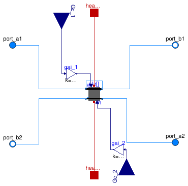
Register for a heat exchanger
Information
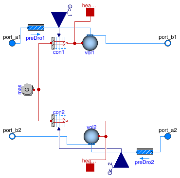
Register of a heat exchanger with dynamics on the fluids and the solid. The register represents one array of pipes that are perpendicular to the air stream. The hA value for both fluids is an input. The driving force for the heat transfer is the temperature difference between the fluid volumes and the solid in each heat exchanger element.
Extends from Buildings.Fluid.Interfaces.FourPortFlowResistanceParameters (Parameters for flow resistance for models with four ports).
Parameters
| Type | Name | Default | Description |
|---|---|---|---|
| replaceable package Medium1 | Modelica.Media.Interfaces.Pa... | Medium 1 in the component | |
| replaceable package Medium2 | Modelica.Media.Interfaces.Pa... | Medium 2 in the component | |
| Integer | nPipPar | 2 | Number of parallel pipes in each register |
| Integer | nPipSeg | 3 | Number of pipe segments per register used for discretization |
| HexElementSensible | ele[nPipPar, nPipSeg] | redeclare Buildings.Fluid.He... | Element of a heat exchanger |
| Nominal condition | |||
| PressureDifference | dp1_nominal | Pressure difference [Pa] | |
| PressureDifference | dp2_nominal | Pressure difference [Pa] | |
| ThermalConductance | UA_nominal | Thermal conductance at nominal flow, used to compute time constant [W/K] | |
| MassFlowRate | m1_flow_nominal | Mass flow rate medim 1 [kg/s] | |
| MassFlowRate | m2_flow_nominal | Mass flow rate medium 2 [kg/s] | |
| Time | tau1 | 20 | Time constant at nominal flow for medium 1 [s] |
| Time | tau2 | 1 | Time constant at nominal flow for medium 2 [s] |
| Time | tau_m | 60 | Time constant of metal at nominal UA value [s] |
| Flow resistance | |||
| Medium 1 | |||
| Boolean | computeFlowResistance1 | true | =true, compute flow resistance. Set to false to assume no friction |
| Boolean | from_dp1 | false | = true, use m_flow = f(dp) else dp = f(m_flow) |
| Boolean | linearizeFlowResistance1 | false | = true, use linear relation between m_flow and dp for any flow rate |
| Real | deltaM1 | 0.1 | Fraction of nominal flow rate where flow transitions to laminar |
| Medium 2 | |||
| Boolean | computeFlowResistance2 | true | =true, compute flow resistance. Set to false to assume no friction |
| Boolean | from_dp2 | false | = true, use m_flow = f(dp) else dp = f(m_flow) |
| Boolean | linearizeFlowResistance2 | false | = true, use linear relation between m_flow and dp for any flow rate |
| Real | deltaM2 | 0.1 | Fraction of nominal flow rate where flow transitions to laminar |
| Advanced | |||
| Boolean | initialize_p1 | not Medium1.singleState | Set to true to initialize the pressure of volume 1 |
| Boolean | initialize_p2 | not Medium2.singleState | Set to true to initialize the pressure of volume 2 |
| Assumptions | |||
| Boolean | allowFlowReversal1 | true | = true to allow flow reversal in medium 1, false restricts to design direction (port_a -> port_b) |
| Boolean | allowFlowReversal2 | true | = true to allow flow reversal in medium 2, false restricts to design direction (port_a -> port_b) |
| Dynamics | |||
| Conservation equations | |||
| Dynamics | energyDynamics | Modelica.Fluid.Types.Dynamic... | Default formulation of energy balances |
Connectors
| Type | Name | Description |
|---|---|---|
| replaceable package Medium1 | Medium 1 in the component | |
| replaceable package Medium2 | Medium 2 in the component | |
| FluidPort_a | port_a1[nPipPar] | Fluid connector a for medium 1 (positive design flow direction is from port_a1 to port_b1) |
| FluidPort_b | port_b1[nPipPar] | Fluid connector b for medium 1 (positive design flow direction is from port_a to port_b) |
| FluidPort_a | port_a2[nPipPar, nPipSeg] | Fluid connector a for medium 2 (positive design flow direction is from port_a2 to port_b2) |
| FluidPort_b | port_b2[nPipPar, nPipSeg] | Fluid connector b for medium 2 (positive design flow direction is from port_a to port_b) |
| HeatPort_a | heaPor1[nPipPar, nPipSeg] | Heat port for heat exchange with the control volume 1 |
| HeatPort_a | heaPor2[nPipPar, nPipSeg] | Heat port for heat exchange with the control volume 2 |
| input RealInput | Gc_2 | Signal representing the convective thermal conductance medium 2 in [W/K] |
| input RealInput | Gc_1 | Signal representing the convective thermal conductance medium 1 in [W/K] |
Modelica definition
 Buildings.Fluid.HeatExchangers.BaseClasses.DuctManifoldFixedResistance
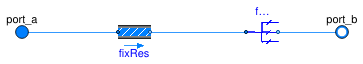
Manifold for a heat exchanger air duct connection
Information
Duct manifold with a fixed flow resistance.
This model is composed of a pressure drop calculation, and
a flow distributor. The flow distributor distributes the
mass flow rate equally to each instance of port_b,
without having to compute a pressure drop in each flow leg.
Note: It is important that there is an equal pressure drop in each flow leg between this model, and the model that collects the flows. Otherwise, no solution may exist, and therefore the simulation may stop with an error.
Extends from PartialDuctManifold (Partial manifold for heat exchanger duct connection).
Parameters
| Type | Name | Default | Description |
|---|---|---|---|
| replaceable package Medium | PartialMedium | Medium in the component | |
| Integer | nPipPar | Number of parallel pipes in each register | |
| Integer | nPipSeg | Number of pipe segments per register used for discretization | |
| Boolean | use_dh | false | Set to true to specify hydraulic diameter |
| Length | dh | 1 | Hydraulic diameter of duct [m] |
| Real | ReC | 4000 | Reynolds number where transition to turbulence starts |
| Real | deltaM | 0.3 | Fraction of nominal mass flow rate where transition to turbulent occurs |
| Initialization | |||
| MassFlowRate | mStart_flow_a | Guess value for mass flow rate at port_a [kg/s] | |
| Nominal Condition | |||
| MassFlowRate | m_flow_nominal | Mass flow rate at port_a [kg/s] | |
| PressureDifference | dp_nominal | Pressure drop [Pa] | |
| Assumptions | |||
| Boolean | allowFlowReversal | true | = true to allow flow reversal, false restricts to design direction (port_a -> port_b) |
| Advanced | |||
| Boolean | linearized | false | = true, use linear relation between m_flow and dp for any flow rate |
| Boolean | from_dp | false | = true, use m_flow = f(dp) else dp = f(m_flow) |
Connectors
| Type | Name | Description |
|---|---|---|
| FluidPort_a | port_a | Fluid connector a for medium (positive design flow direction is from port_a to port_b) |
| FluidPort_b | port_b[nPipPar, nPipSeg] | Fluid connector b for medium (positive design flow direction is from port_a to port_b) |
Modelica definition
 Buildings.Fluid.HeatExchangers.BaseClasses.DuctManifoldFlowDistributor
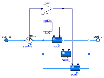
Manifold for duct inlet that distributes the mass flow rate equally
Information
This model distributes the mass flow rates equally between all instances
of port_b.
The model connects the flows between the ports without modeling flow friction. The model is used in conjunction with a manifold that is added to the other side of the heat exchanger registers.
Note: It is important that there is an equal pressure drop in each flow leg between this model, and the model that collects the flows. Otherwise, no solution may exist. Hence, only use this model if you know what you are doing.
Extends from PartialDuctManifold (Partial manifold for heat exchanger duct connection).
Parameters
| Type | Name | Default | Description |
|---|---|---|---|
| replaceable package Medium | PartialMedium | Medium in the component | |
| Integer | nPipPar | Number of parallel pipes in each register | |
| Integer | nPipSeg | Number of pipe segments per register used for discretization | |
| Initialization | |||
| MassFlowRate | mStart_flow_a | Guess value for mass flow rate at port_a [kg/s] | |
| Nominal Condition | |||
| MassFlowRate | m_flow_nominal | Mass flow rate at port_a [kg/s] | |
| Assumptions | |||
| Boolean | allowFlowReversal | true | = true to allow flow reversal, false restricts to design direction (port_a -> port_b) |
Connectors
| Type | Name | Description |
|---|---|---|
| FluidPort_a | port_a | Fluid connector a for medium (positive design flow direction is from port_a to port_b) |
| FluidPort_b | port_b[nPipPar, nPipSeg] | Fluid connector b for medium (positive design flow direction is from port_a to port_b) |
Modelica definition
 Buildings.Fluid.HeatExchangers.BaseClasses.DuctManifoldNoResistance
Duct manifold without resistance
Information
Duct manifold without flow resistance.
This model connects the flows between the ports without modeling flow friction. The model is used in conjunction with a manifold which contains pressure drop elements and that is added to the other side of the heat exchanger registers.
Extends from PartialDuctManifold (Partial manifold for heat exchanger duct connection).
Parameters
| Type | Name | Default | Description |
|---|---|---|---|
| replaceable package Medium | PartialMedium | Medium in the component | |
| Integer | nPipPar | Number of parallel pipes in each register | |
| Integer | nPipSeg | Number of pipe segments per register used for discretization | |
| Initialization | |||
| MassFlowRate | mStart_flow_a | Guess value for mass flow rate at port_a [kg/s] | |
| Assumptions | |||
| Boolean | allowFlowReversal | true | = true to allow flow reversal, false restricts to design direction (port_a -> port_b) |
Connectors
| Type | Name | Description |
|---|---|---|
| FluidPort_a | port_a | Fluid connector a for medium (positive design flow direction is from port_a to port_b) |
| FluidPort_b | port_b[nPipPar, nPipSeg] | Fluid connector b for medium (positive design flow direction is from port_a to port_b) |
Modelica definition
 Buildings.Fluid.HeatExchangers.BaseClasses.HACoilInside
Calculates the hA value for water inside a coil
Information
Model for convective heat transfer coefficients inside a coil. Optionally, the convective heat transfer coefficient can be computed as a function of temperature and mass flow rate.
Extends from Modelica.Blocks.Icons.Block (Basic graphical layout of input/output block).
Parameters
| Type | Name | Default | Description |
|---|---|---|---|
| Real | n | 0.85 | Water-side exponent for convective heat transfer coefficient, h proportional to m_flow^n |
| Nominal condition | |||
| MassFlowRate | m_flow_nominal | Water mass flow rate [kg/s] | |
| ThermalConductance | hA_nominal | Convective heat transfer coefficient [W/K] | |
| Temperature | T_nominal | Modelica.Units.Conversions.f... | Nominal water temperature [K] |
| Advanced | |||
| Modeling detail | |||
| Boolean | flowDependent | true | Set to false to make hA independent of mass flow rate |
| Boolean | temperatureDependent | true | Set to false to make hA independent of temperature |
Connectors
| Type | Name | Description |
|---|---|---|
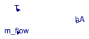
| input RealInput | m_flow | Mass flow rate [kg/s] |
| input RealInput | T | Temperature [K] |
| output RealOutput | hA | Inside convective heat transfer [W/K] |
Modelica definition
 Buildings.Fluid.HeatExchangers.BaseClasses.HADryCoil
Sensible convective heat transfer model for air to water coil
Information
Model for sensible convective heat transfer coefficients for an air to water coil.
This model computes the convective heat transfer coefficient for an air to water coil. The parameters allow a user to enable or disable, individually for each medium, the mass flow and/or the temperature dependence of the convective heat transfer coefficients. For a detailed explanation of the equation, see the references below.
References
- Wetter Michael, Simulation model finned water-air-coil without condensation, LBNL-42355, Lawrence Berkeley National Laboratory, Berkeley, CA, 1999.
- Wetter Michael, Simulation model air-to-air plate heat exchanger, LBNL-42354, Lawrence Berkeley National Laboratory, Berkeley, CA, 1999.
Extends from Modelica.Blocks.Icons.Block (Basic graphical layout of input/output block).
Parameters
| Type | Name | Default | Description |
|---|---|---|---|
| Real | n_w | 0.85 | Water-side exponent for convective heat transfer coefficient, h~m_flow^n |
| Real | n_a | 0.8 | Air-side exponent for convective heat transfer coefficient, h~m_flow^n |
| Nominal condition | |||
| ThermalConductance | UA_nominal | Thermal conductance at nominal flow [W/K] | |
| MassFlowRate | m_flow_nominal_w | Water mass flow rate [kg/s] | |
| MassFlowRate | m_flow_nominal_a | Air mass flow rate [kg/s] | |
| Real | r_nominal | 0.5 | Ratio between air-side and water-side convective heat transfer coefficient |
| ThermalConductance | hA_nominal_w | UA_nominal*(r_nominal + 1)/r... | Water side convective heat transfer coefficient [W/K] |
| ThermalConductance | hA_nominal_a | r_nominal*hA_nominal_w | Air side convective heat transfer coefficient, including fin resistance [W/K] |
| Temperature | T0_w | Modelica.Units.Conversions.f... | Water temperature [K] |
| Temperature | T0_a | Modelica.Units.Conversions.f... | Air temperature [K] |
| Advanced | |||
| Modeling detail | |||
| Boolean | waterSideFlowDependent | true | Set to false to make water-side hA independent of mass flow rate |
| Boolean | airSideFlowDependent | true | Set to false to make air-side hA independent of mass flow rate |
| Boolean | waterSideTemperatureDependent | true | Set to false to make water-side hA independent of temperature |
| Boolean | airSideTemperatureDependent | true | Set to false to make air-side hA independent of temperature |
Connectors
| Type | Name | Description |
|---|---|---|
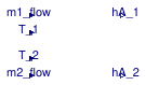
| input RealInput | m1_flow | Mass flow rate medium 1 [kg/s] |
| input RealInput | m2_flow | Mass flow rate medium 2 [kg/s] |
| input RealInput | T_1 | Temperature medium 1 [K] |
| input RealInput | T_2 | Temperature medium 2 [K] |
| output RealOutput | hA_1 | Convective heat transfer medium 1 [W/K] |
| output RealOutput | hA_2 | Convective heat transfer medium 2 [W/K] |
Modelica definition
 Buildings.Fluid.HeatExchangers.BaseClasses.HANaturalCylinder
Calculates an hA value for natural convection around a cylinder
Information
This model calculates the convection coefficient h for natural convection from a cylinder submerged in fluid. h is calcualted using Eq 9.34 from Incropera and DeWitt (1996). Output of the block is the hA value.
The Nusselt number is computed as
NuD = (0.6 + (0.387 RaD(1/6))/(1+(0.559 Pr) (9/16))(8/27))2);
where NuD is the Nusselt number, RaD is the
Rayleigh number and
Pr is the Prandtl number.
This correclation is accurate for RaD less than 1012.
h is then calculated from the Nusselt number. The equation is
h = NuD k/D
where k is the thermal conductivity of the fluid and D is the diameter of the submerged cylinder.
References
Fundamentals of Heat and Mass Transfer (Fourth Edition), Frank Incropera and David DeWitt, John Wiley and Sons, 1996
Extends from Modelica.Blocks.Icons.Block (Basic graphical layout of input/output block).
Parameters
| Type | Name | Default | Description |
|---|---|---|---|
| replaceable package Medium | Modelica.Media.Interfaces.Pa... | Medium inside the tank | |
| Diameter | ChaLen | Characteristic length of the cylinder [m] | |
| Nominal condition | |||
| ThermalConductance | hA_nominal | Convective heat transfer coefficient [W/K] | |
| Temperature | TFlu_nominal | Fluid temperature at hA_nominal [K] | |
| Temperature | TSur_nominal | Surface temperature at hA_nominal [K] | |
Connectors
| Type | Name | Description |
|---|---|---|
| replaceable package Medium | Medium inside the tank | |
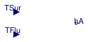
| input RealInput | TSur | Temperature of the external surface of the heat exchanger [K] |
| input RealInput | TFlu | Temperature of the fluid in the heat exchanger [K] |
| output RealOutput | hA | hA-value of the heat exchanger [W/K] |
Modelica definition
 Buildings.Fluid.HeatExchangers.BaseClasses.HexElementLatent
Element of a heat exchanger with humidity condensation of fluid 2
Information
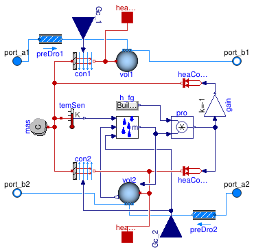
Element of a heat exchanger with humidity condensation of fluid 2 and with dynamics of the fluids and the solid.
See
Buildings.Fluid.HeatExchangers.BaseClasses.PartialHexElement
for a description of the physics of the sensible heat exchange.
For the latent heat exchange, this model removes water vapor from the air stream, as
computed by the instance masExc, and deposits it on the coil.
Hence, the latent heat is treated such that it transfers to the coil surface.
The latent heat is removed from the air stream using heat flow source heaConVapAir
and deposited on the coil surface using heat flow source heaConVapCoi.
Note that the driving potential for latent heat transfer is the temperature of the instance mas.
This is an approximation as it neglects the thermal resistance of the water film that builds up on the coil.
Extends from Buildings.Fluid.HeatExchangers.BaseClasses.PartialHexElement (Element of a heat exchanger 2).
Parameters
| Type | Name | Default | Description |
|---|---|---|---|
| replaceable package Medium1 | PartialMedium | Medium 1 in the component | |
| replaceable package Medium2 | PartialMedium | Medium 2 in the component | |
| HeatCapacity | C | 2*UA_nominal*tau_m | Heat capacity of metal (= cp*m) [J/K] |
| Nominal condition | |||
| MassFlowRate | m1_flow_nominal | Nominal mass flow rate [kg/s] | |
| MassFlowRate | m2_flow_nominal | Nominal mass flow rate [kg/s] | |
| PressureDifference | dp1_nominal | Pressure difference [Pa] | |
| PressureDifference | dp2_nominal | Pressure difference [Pa] | |
| ThermalConductance | UA_nominal | Thermal conductance at nominal flow, used to compute time constant [W/K] | |
| Time | tau_m | 60 | Time constant of metal at nominal UA value [s] |
| Assumptions | |||
| Boolean | allowFlowReversal1 | true | = false to simplify equations, assuming, but not enforcing, no flow reversal for medium 1 |
| Boolean | allowFlowReversal2 | true | = false to simplify equations, assuming, but not enforcing, no flow reversal for medium 2 |
| Advanced | |||
| MassFlowRate | m1_flow_small | 1E-4*abs(m1_flow_nominal) | Small mass flow rate for regularization of zero flow [kg/s] |
| MassFlowRate | m2_flow_small | 1E-4*abs(m2_flow_nominal) | Small mass flow rate for regularization of zero flow [kg/s] |
| Boolean | initialize_p1 | not Medium1.singleState | Set to true to initialize the pressure of volume 1 |
| Boolean | initialize_p2 | not Medium2.singleState | Set to true to initialize the pressure of volume 2 |
| Diagnostics | |||
| Boolean | show_T | false | = true, if actual temperature at port is computed |
| Flow resistance | |||
| Medium 1 | |||
| Boolean | from_dp1 | false | = true, use m_flow = f(dp) else dp = f(m_flow) |
| Boolean | linearizeFlowResistance1 | false | = true, use linear relation between m_flow and dp for any flow rate |
| Real | deltaM1 | 0.1 | Fraction of nominal flow rate where flow transitions to laminar |
| Medium 2 | |||
| Boolean | from_dp2 | false | = true, use m_flow = f(dp) else dp = f(m_flow) |
| Boolean | linearizeFlowResistance2 | false | = true, use linear relation between m_flow and dp for any flow rate |
| Real | deltaM2 | 0.1 | Fraction of nominal flow rate where flow transitions to laminar |
| Dynamics | |||
| Nominal condition | |||
| Time | tau1 | 30 | Time constant at nominal flow [s] |
| Time | tau2 | 30 | Time constant at nominal flow [s] |
| Conservation equations | |||
| Dynamics | energyDynamics | Modelica.Fluid.Types.Dynamic... | Type of energy balance: dynamic (3 initialization options) or steady state |
| Initialization | |||
| Medium 1 | |||
| AbsolutePressure | p1_start | Medium1.p_default | Start value of pressure [Pa] |
| Temperature | T1_start | Medium1.T_default | Start value of temperature [K] |
| MassFraction | X1_start[Medium1.nX] | Medium1.X_default | Start value of mass fractions m_i/m [kg/kg] |
| ExtraProperty | C1_start[Medium1.nC] | fill(0, Medium1.nC) | Start value of trace substances |
| ExtraProperty | C1_nominal[Medium1.nC] | fill(1E-2, Medium1.nC) | Nominal value of trace substances. (Set to typical order of magnitude.) |
| Medium 2 | |||
| AbsolutePressure | p2_start | Medium2.p_default | Start value of pressure [Pa] |
| Temperature | T2_start | Medium2.T_default | Start value of temperature [K] |
| MassFraction | X2_start[Medium2.nX] | Medium2.X_default | Start value of mass fractions m_i/m [kg/kg] |
| ExtraProperty | C2_start[Medium2.nC] | fill(0, Medium2.nC) | Start value of trace substances |
| ExtraProperty | C2_nominal[Medium2.nC] | fill(1E-2, Medium2.nC) | Nominal value of trace substances. (Set to typical order of magnitude.) |
Connectors
| Type | Name | Description |
|---|---|---|
| FluidPort_a | port_a1 | Fluid connector a1 (positive design flow direction is from port_a1 to port_b1) |
| FluidPort_b | port_b1 | Fluid connector b1 (positive design flow direction is from port_a1 to port_b1) |
| FluidPort_a | port_a2 | Fluid connector a2 (positive design flow direction is from port_a2 to port_b2) |
| FluidPort_b | port_b2 | Fluid connector b2 (positive design flow direction is from port_a2 to port_b2) |
| input RealInput | Gc_1 | Signal representing the convective thermal conductance medium 1 in [W/K] |
| input RealInput | Gc_2 | Signal representing the convective thermal conductance medium 2 in [W/K] |
| HeatPort_a | heaPor1 | Heat port for heat exchange with the control volume 1 |
| HeatPort_a | heaPor2 | Heat port for heat exchange with the control volume 2 |
Modelica definition
 Buildings.Fluid.HeatExchangers.BaseClasses.HexElementSensible
Element of a heat exchanger with no humidity condensation
Information
Element of a heat exchanger with humidity condensation and with dynamics of the fluids and the solid.
See Buildings.Fluid.HeatExchangers.BaseClasses.PartialHexElement for a description of the physics.
Extends from Buildings.Fluid.HeatExchangers.BaseClasses.PartialHexElement (Element of a heat exchanger 2).
Parameters
| Type | Name | Default | Description |
|---|---|---|---|
| replaceable package Medium1 | PartialMedium | Medium 1 in the component | |
| replaceable package Medium2 | PartialMedium | Medium 2 in the component | |
| HeatCapacity | C | 2*UA_nominal*tau_m | Heat capacity of metal (= cp*m) [J/K] |
| Nominal condition | |||
| MassFlowRate | m1_flow_nominal | Nominal mass flow rate [kg/s] | |
| MassFlowRate | m2_flow_nominal | Nominal mass flow rate [kg/s] | |
| PressureDifference | dp1_nominal | Pressure difference [Pa] | |
| PressureDifference | dp2_nominal | Pressure difference [Pa] | |
| ThermalConductance | UA_nominal | Thermal conductance at nominal flow, used to compute time constant [W/K] | |
| Time | tau_m | 60 | Time constant of metal at nominal UA value [s] |
| Assumptions | |||
| Boolean | allowFlowReversal1 | true | = false to simplify equations, assuming, but not enforcing, no flow reversal for medium 1 |
| Boolean | allowFlowReversal2 | true | = false to simplify equations, assuming, but not enforcing, no flow reversal for medium 2 |
| Advanced | |||
| MassFlowRate | m1_flow_small | 1E-4*abs(m1_flow_nominal) | Small mass flow rate for regularization of zero flow [kg/s] |
| MassFlowRate | m2_flow_small | 1E-4*abs(m2_flow_nominal) | Small mass flow rate for regularization of zero flow [kg/s] |
| Boolean | initialize_p1 | not Medium1.singleState | Set to true to initialize the pressure of volume 1 |
| Boolean | initialize_p2 | not Medium2.singleState | Set to true to initialize the pressure of volume 2 |
| Diagnostics | |||
| Boolean | show_T | false | = true, if actual temperature at port is computed |
| Flow resistance | |||
| Medium 1 | |||
| Boolean | from_dp1 | false | = true, use m_flow = f(dp) else dp = f(m_flow) |
| Boolean | linearizeFlowResistance1 | false | = true, use linear relation between m_flow and dp for any flow rate |
| Real | deltaM1 | 0.1 | Fraction of nominal flow rate where flow transitions to laminar |
| Medium 2 | |||
| Boolean | from_dp2 | false | = true, use m_flow = f(dp) else dp = f(m_flow) |
| Boolean | linearizeFlowResistance2 | false | = true, use linear relation between m_flow and dp for any flow rate |
| Real | deltaM2 | 0.1 | Fraction of nominal flow rate where flow transitions to laminar |
| Dynamics | |||
| Nominal condition | |||
| Time | tau1 | 30 | Time constant at nominal flow [s] |
| Time | tau2 | 30 | Time constant at nominal flow [s] |
| Conservation equations | |||
| Dynamics | energyDynamics | Modelica.Fluid.Types.Dynamic... | Type of energy balance: dynamic (3 initialization options) or steady state |
| Initialization | |||
| Medium 1 | |||
| AbsolutePressure | p1_start | Medium1.p_default | Start value of pressure [Pa] |
| Temperature | T1_start | Medium1.T_default | Start value of temperature [K] |
| MassFraction | X1_start[Medium1.nX] | Medium1.X_default | Start value of mass fractions m_i/m [kg/kg] |
| ExtraProperty | C1_start[Medium1.nC] | fill(0, Medium1.nC) | Start value of trace substances |
| ExtraProperty | C1_nominal[Medium1.nC] | fill(1E-2, Medium1.nC) | Nominal value of trace substances. (Set to typical order of magnitude.) |
| Medium 2 | |||
| AbsolutePressure | p2_start | Medium2.p_default | Start value of pressure [Pa] |
| Temperature | T2_start | Medium2.T_default | Start value of temperature [K] |
| MassFraction | X2_start[Medium2.nX] | Medium2.X_default | Start value of mass fractions m_i/m [kg/kg] |
| ExtraProperty | C2_start[Medium2.nC] | fill(0, Medium2.nC) | Start value of trace substances |
| ExtraProperty | C2_nominal[Medium2.nC] | fill(1E-2, Medium2.nC) | Nominal value of trace substances. (Set to typical order of magnitude.) |
Connectors
| Type | Name | Description |
|---|---|---|
| FluidPort_a | port_a1 | Fluid connector a1 (positive design flow direction is from port_a1 to port_b1) |
| FluidPort_b | port_b1 | Fluid connector b1 (positive design flow direction is from port_a1 to port_b1) |
| FluidPort_a | port_a2 | Fluid connector a2 (positive design flow direction is from port_a2 to port_b2) |
| FluidPort_b | port_b2 | Fluid connector b2 (positive design flow direction is from port_a2 to port_b2) |
| input RealInput | Gc_1 | Signal representing the convective thermal conductance medium 1 in [W/K] |
| input RealInput | Gc_2 | Signal representing the convective thermal conductance medium 2 in [W/K] |
| HeatPort_a | heaPor1 | Heat port for heat exchange with the control volume 1 |
| HeatPort_a | heaPor2 | Heat port for heat exchange with the control volume 2 |
Modelica definition
 Buildings.Fluid.HeatExchangers.BaseClasses.MassExchange
Block to compute the latent heat transfer based on the Lewis number
Information
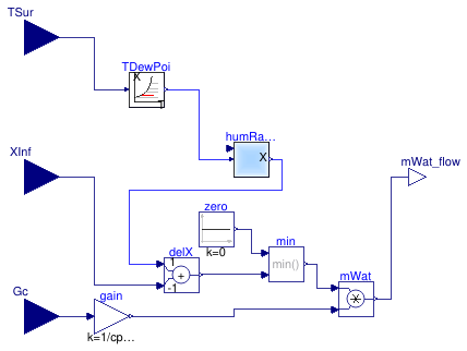
This model computes the mass transfer based on similarity laws between the convective sensible heat transfer coefficient and the mass transfer coefficient.
Using the Lewis number which is defined as the ratio between the heat and mass diffusion coefficients, one can obtain the ratio between convection heat transfer coefficient h in (W/(m^2*K)) and mass transfer coefficient hm in (m/s) as follows:
h ⁄ hm = ρ cp Le(1-n) ⁄ hm
where ρ is the mass density, cp is the specific heat capacity of the bulk medium and n is a coefficient from the boundary layer analysis, which is typically n=1/3. From this equation, we can compute the water vapor mass flow rate nA in (kg/s) as
nA = Gc ⁄ (cp Le(1-n)) (Xs - X∞),
where Gc is the sensible heat conductivity in (W/K) and Xs and X∞ are the water vapor mass per unit volume in the boundary layer and in the bulk of the medium. In this model, Xs is the saturation water vapor pressure corresponding to the temperature Tsur which is an input.
Extends from Buildings.BaseClasses.BaseIcon (Base icon).
Parameters
| Type | Name | Default | Description |
|---|---|---|---|
| replaceable package Medium | Modelica.Media.Interfaces.Pa... | Fluid medium model | |
| Real | Le | 1 | Lewis number (around 1 for water vapor in air) |
| Real | n | 1/3 | Exponent in bondary layer ratio, delta/delta_t = Pr^n |
Connectors
| Type | Name | Description |
|---|---|---|
| replaceable package Medium | Fluid medium model | |
| input RealInput | XInf | Water mass fraction of medium |
| input RealInput | TSur | Surface temperature [K] |
| output RealOutput | mWat_flow | Water flow rate [kg/s] |
| input RealInput | Gc | Signal representing the convective (sensible) thermal conductance in [W/K] |
Modelica definition
Buildings.Fluid.HeatExchangers.BaseClasses.PartialDuctManifold
Partial manifold for heat exchanger duct connection

Information
Partial duct manifold for a heat exchanger.
This model defines the duct connection to a heat exchanger. It is extended by other models that model the flow connection between the ports with and without flow friction.
Extends from PartialDuctPipeManifold (Partial heat exchanger duct and pipe manifold).
Parameters
| Type | Name | Default | Description |
|---|---|---|---|
| replaceable package Medium | PartialMedium | Medium in the component | |
| Integer | nPipPar | Number of parallel pipes in each register | |
| Integer | nPipSeg | Number of pipe segments per register used for discretization | |
| Initialization | |||
| MassFlowRate | mStart_flow_a | Guess value for mass flow rate at port_a [kg/s] | |
| Assumptions | |||
| Boolean | allowFlowReversal | true | = true to allow flow reversal, false restricts to design direction (port_a -> port_b) |
Connectors
| Type | Name | Description |
|---|---|---|
| FluidPort_a | port_a | Fluid connector a for medium (positive design flow direction is from port_a to port_b) |
| FluidPort_b | port_b[nPipPar, nPipSeg] | Fluid connector b for medium (positive design flow direction is from port_a to port_b) |
Modelica definition
 Buildings.Fluid.HeatExchangers.BaseClasses.PartialDuctPipeManifold
Partial heat exchanger duct and pipe manifold

Information
Partial heat exchanger manifold. This partial model defines ports and parameters that are used for air-side and water-side heat exchanger manifolds.
Extends from Buildings.BaseClasses.BaseIcon (Base icon).
Parameters
| Type | Name | Default | Description |
|---|---|---|---|
| replaceable package Medium | Modelica.Media.Interfaces.Pa... | Medium in the component | |
| Integer | nPipPar | Number of parallel pipes in each register | |
| Initialization | |||
| MassFlowRate | mStart_flow_a | Guess value for mass flow rate at port_a [kg/s] | |
| Assumptions | |||
| Boolean | allowFlowReversal | true | = true to allow flow reversal, false restricts to design direction (port_a -> port_b) |
Connectors
| Type | Name | Description |
|---|---|---|
| replaceable package Medium | Medium in the component | |
| FluidPort_a | port_a | Fluid connector a for medium (positive design flow direction is from port_a to port_b) |
Modelica definition
 Buildings.Fluid.HeatExchangers.BaseClasses.PartialEffectiveness
Partial model to implement heat exchangers based on effectiveness model

Information
Partial model to implement heat exchanger models.
Classes that extend this model need to implement heat and mass balance equations in a form like
  // transferred heat
  Q1_flow = eps * QMax_flow;
  // no heat loss to ambient
  0 = Q1_flow + Q2_flow;
  // no mass exchange
  mXi1_flow = zeros(Medium1.nXi);
  mXi2_flow = zeros(Medium2.nXi);
Thus, if medium 1 is heated in this device, then Q1_flow > 0
and QMax_flow > 0.
Extends from Fluid.Interfaces.StaticFourPortHeatMassExchanger (Partial model transporting two fluid streams between four ports without storing mass or energy).
Parameters
| Type | Name | Default | Description |
|---|---|---|---|
| replaceable package Medium1 | PartialMedium | Medium 1 in the component | |
| replaceable package Medium2 | PartialMedium | Medium 2 in the component | |
| Boolean | sensibleOnly1 | Set to true if sensible exchange only for medium 1 | |
| Boolean | sensibleOnly2 | Set to true if sensible exchange only for medium 2 | |
| Nominal condition | |||
| MassFlowRate | m1_flow_nominal | Nominal mass flow rate [kg/s] | |
| MassFlowRate | m2_flow_nominal | Nominal mass flow rate [kg/s] | |
| PressureDifference | dp1_nominal | Pressure difference [Pa] | |
| PressureDifference | dp2_nominal | Pressure difference [Pa] | |
| Assumptions | |||
| Boolean | allowFlowReversal1 | true | = false to simplify equations, assuming, but not enforcing, no flow reversal for medium 1 |
| Boolean | allowFlowReversal2 | true | = false to simplify equations, assuming, but not enforcing, no flow reversal for medium 2 |
| Advanced | |||
| MassFlowRate | m1_flow_small | 1E-4*abs(m1_flow_nominal) | Small mass flow rate for regularization of zero flow [kg/s] |
| MassFlowRate | m2_flow_small | 1E-4*abs(m2_flow_nominal) | Small mass flow rate for regularization of zero flow [kg/s] |
| Diagnostics | |||
| Boolean | show_T | false | = true, if actual temperature at port is computed |
| Flow resistance | |||
| Medium 1 | |||
| Boolean | from_dp1 | false | = true, use m_flow = f(dp) else dp = f(m_flow) |
| Boolean | linearizeFlowResistance1 | false | = true, use linear relation between m_flow and dp for any flow rate |
| Real | deltaM1 | 0.1 | Fraction of nominal flow rate where flow transitions to laminar |
| Medium 2 | |||
| Boolean | from_dp2 | false | = true, use m_flow = f(dp) else dp = f(m_flow) |
| Boolean | linearizeFlowResistance2 | false | = true, use linear relation between m_flow and dp for any flow rate |
| Real | deltaM2 | 0.1 | Fraction of nominal flow rate where flow transitions to laminar |
Connectors
| Type | Name | Description |
|---|---|---|
| FluidPort_a | port_a1 | Fluid connector a1 (positive design flow direction is from port_a1 to port_b1) |
| FluidPort_b | port_b1 | Fluid connector b1 (positive design flow direction is from port_a1 to port_b1) |
| FluidPort_a | port_a2 | Fluid connector a2 (positive design flow direction is from port_a2 to port_b2) |
| FluidPort_b | port_b2 | Fluid connector b2 (positive design flow direction is from port_a2 to port_b2) |
Modelica definition
 Buildings.Fluid.HeatExchangers.BaseClasses.PartialEffectivenessNTU
Partial model for heat exchanger with effectiveness - NTU relation and no moisture condensation
Information
Partial model of a heat exchanger without humidity condensation. This model transfers heat in the amount of
Q = Qmax ε
ε = f(NTU, Z, flowRegime),
where Qmax is the maximum heat that can be transferred, ε is the heat transfer effectiveness, NTU is the Number of Transfer Units, Z is the ratio of minimum to maximum capacity flow rate and flowRegime is the heat exchanger flow regime. such as parallel flow, cross flow or counter flow.
The flow regimes depend on the heat exchanger configuration. All configurations defined in Buildings.Fluid.Types.HeatExchangerConfiguration are supported.
By default, the flow regime, such as counter flow or parallel flow,
is kept constant based on the parameter value configuration.
If a flow reverses direction, it is not changed, e.g.,
a heat exchanger does not change from counter flow to parallel flow
if one flow changes direction.
To dynamically change the flow regime,
set the constant use_dynamicFlowRegime to
true.
However, use_dynamicFlowRegime=true
can cause slower simulation due to events.
Models that extend from this partial model need to provide an assignment
for UA.
Extends from Buildings.Fluid.HeatExchangers.BaseClasses.PartialEffectiveness (Partial model to implement heat exchangers based on effectiveness model).
Parameters
| Type | Name | Default | Description |
|---|---|---|---|
| replaceable package Medium1 | PartialMedium | Medium 1 in the component | |
| replaceable package Medium2 | PartialMedium | Medium 2 in the component | |
| HeatFlowRate | Q1_flow | eps*QMax_flow | Heat transferred into the medium 1 [W] |
| MassFlowRate | mWat1_flow | 0 | Moisture mass flow rate added to the medium 1 [kg/s] |
| HeatFlowRate | Q2_flow | -Q1_flow | Heat transferred into the medium 2 [W] |
| MassFlowRate | mWat2_flow | 0 | Moisture mass flow rate added to the medium 2 [kg/s] |
| Boolean | sensibleOnly1 | true | Set to true if sensible exchange only for medium 1 |
| Boolean | sensibleOnly2 | true | Set to true if sensible exchange only for medium 2 |
| HeatExchangerConfiguration | configuration | Heat exchanger configuration | |
| Nominal condition | |||
| MassFlowRate | m1_flow_nominal | Nominal mass flow rate [kg/s] | |
| MassFlowRate | m2_flow_nominal | Nominal mass flow rate [kg/s] | |
| PressureDifference | dp1_nominal | Pressure difference [Pa] | |
| PressureDifference | dp2_nominal | Pressure difference [Pa] | |
| Nominal thermal performance | |||
| Boolean | use_Q_flow_nominal | true | Set to true to specify Q_flow_nominal and temperatures, or to false to specify effectiveness |
| HeatFlowRate | Q_flow_nominal | Nominal heat flow rate (positive for heat transfer from 1 to 2) [W] | |
| Temperature | T_a1_nominal | Nominal temperature at port a1 [K] | |
| Temperature | T_a2_nominal | Nominal temperature at port a2 [K] | |
| Real | eps_nominal | Nominal heat transfer effectiveness | |
| Assumptions | |||
| Boolean | allowFlowReversal1 | true | = false to simplify equations, assuming, but not enforcing, no flow reversal for medium 1 |
| Boolean | allowFlowReversal2 | true | = false to simplify equations, assuming, but not enforcing, no flow reversal for medium 2 |
| Advanced | |||
| MassFlowRate | m1_flow_small | 1E-4*abs(m1_flow_nominal) | Small mass flow rate for regularization of zero flow [kg/s] |
| MassFlowRate | m2_flow_small | 1E-4*abs(m2_flow_nominal) | Small mass flow rate for regularization of zero flow [kg/s] |
| Diagnostics | |||
| Boolean | show_T | false | = true, if actual temperature at port is computed |
| Flow resistance | |||
| Medium 1 | |||
| Boolean | from_dp1 | false | = true, use m_flow = f(dp) else dp = f(m_flow) |
| Boolean | linearizeFlowResistance1 | false | = true, use linear relation between m_flow and dp for any flow rate |
| Real | deltaM1 | 0.1 | Fraction of nominal flow rate where flow transitions to laminar |
| Medium 2 | |||
| Boolean | from_dp2 | false | = true, use m_flow = f(dp) else dp = f(m_flow) |
| Boolean | linearizeFlowResistance2 | false | = true, use linear relation between m_flow and dp for any flow rate |
| Real | deltaM2 | 0.1 | Fraction of nominal flow rate where flow transitions to laminar |
Connectors
| Type | Name | Description |
|---|---|---|
| FluidPort_a | port_a1 | Fluid connector a1 (positive design flow direction is from port_a1 to port_b1) |
| FluidPort_b | port_b1 | Fluid connector b1 (positive design flow direction is from port_a1 to port_b1) |
| FluidPort_a | port_a2 | Fluid connector a2 (positive design flow direction is from port_a2 to port_b2) |
| FluidPort_b | port_b2 | Fluid connector b2 (positive design flow direction is from port_a2 to port_b2) |
Modelica definition
Buildings.Fluid.HeatExchangers.BaseClasses.PartialHexElement
Element of a heat exchanger 2
Information
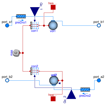
Element of a heat exchanger with dynamics of the fluids and the solid. The hA value for both fluids is an input. The driving force for the heat transfer is the temperature difference between the fluid volumes and the solid.
The heat capacity C of the metal is assigned as follows. Suppose the metal temperature is governed by
C dT ⁄ dt = (hA)1 (T1 - T) + (hA)2 (T2 - T)
where hA are the convective heat transfer coefficients times heat transfer area that also take into account heat conduction in the heat exchanger fins and T1 and T2 are the medium temperatures. Assuming (hA)1=(hA)2, this equation can be rewritten as
C dT ⁄ dt = 2 (UA)0 ( (T1 - T) + (T2 - T) )
where (UA)0 is the UA value at nominal conditions. Hence we set the heat capacity of the metal to
C = 2 (UA)0 τm
where τm is the time constant that the metal of the heat exchanger has if the metal is approximated by a lumped thermal mass.
Note: This model is introduced to allow the instances
Buildings.Fluid.HeatExchangers.BaseClasses.HexElementLatent
and
Buildings.Fluid.HeatExchangers.BaseClasses.HexElementSensible
to redeclare the volume as final, thereby avoiding
that a GUI displays the volume as a replaceable component.
Extends from Buildings.Fluid.Interfaces.FourPortHeatMassExchanger (Model transporting two fluid streams between four ports with storing mass or energy).
Parameters
| Type | Name | Default | Description |
|---|---|---|---|
| replaceable package Medium1 | PartialMedium | Medium 1 in the component | |
| replaceable package Medium2 | PartialMedium | Medium 2 in the component | |
| MixingVolumeHeatPort | vol1 | redeclare Buildings.Fluid.Mi... | Volume for fluid 1 |
| MixingVolume | vol2 | redeclare Buildings.Fluid.Mi... | Volume for fluid 2 |
| HeatCapacity | C | 2*UA_nominal*tau_m | Heat capacity of metal (= cp*m) [J/K] |
| Nominal condition | |||
| MassFlowRate | m1_flow_nominal | Nominal mass flow rate [kg/s] | |
| MassFlowRate | m2_flow_nominal | Nominal mass flow rate [kg/s] | |
| PressureDifference | dp1_nominal | Pressure difference [Pa] | |
| PressureDifference | dp2_nominal | Pressure difference [Pa] | |
| ThermalConductance | UA_nominal | Thermal conductance at nominal flow, used to compute time constant [W/K] | |
| Time | tau_m | 60 | Time constant of metal at nominal UA value [s] |
| Assumptions | |||
| Boolean | allowFlowReversal1 | true | = false to simplify equations, assuming, but not enforcing, no flow reversal for medium 1 |
| Boolean | allowFlowReversal2 | true | = false to simplify equations, assuming, but not enforcing, no flow reversal for medium 2 |
| Advanced | |||
| MassFlowRate | m1_flow_small | 1E-4*abs(m1_flow_nominal) | Small mass flow rate for regularization of zero flow [kg/s] |
| MassFlowRate | m2_flow_small | 1E-4*abs(m2_flow_nominal) | Small mass flow rate for regularization of zero flow [kg/s] |
| Boolean | initialize_p1 | not Medium1.singleState | Set to true to initialize the pressure of volume 1 |
| Boolean | initialize_p2 | not Medium2.singleState | Set to true to initialize the pressure of volume 2 |
| Diagnostics | |||
| Boolean | show_T | false | = true, if actual temperature at port is computed |
| Flow resistance | |||
| Medium 1 | |||
| Boolean | from_dp1 | false | = true, use m_flow = f(dp) else dp = f(m_flow) |
| Boolean | linearizeFlowResistance1 | false | = true, use linear relation between m_flow and dp for any flow rate |
| Real | deltaM1 | 0.1 | Fraction of nominal flow rate where flow transitions to laminar |
| Medium 2 | |||
| Boolean | from_dp2 | false | = true, use m_flow = f(dp) else dp = f(m_flow) |
| Boolean | linearizeFlowResistance2 | false | = true, use linear relation between m_flow and dp for any flow rate |
| Real | deltaM2 | 0.1 | Fraction of nominal flow rate where flow transitions to laminar |
| Dynamics | |||
| Nominal condition | |||
| Time | tau1 | 30 | Time constant at nominal flow [s] |
| Time | tau2 | 30 | Time constant at nominal flow [s] |
| Conservation equations | |||
| Dynamics | energyDynamics | Modelica.Fluid.Types.Dynamic... | Type of energy balance: dynamic (3 initialization options) or steady state |
| Initialization | |||
| Medium 1 | |||
| AbsolutePressure | p1_start | Medium1.p_default | Start value of pressure [Pa] |
| Temperature | T1_start | Medium1.T_default | Start value of temperature [K] |
| MassFraction | X1_start[Medium1.nX] | Medium1.X_default | Start value of mass fractions m_i/m [kg/kg] |
| ExtraProperty | C1_start[Medium1.nC] | fill(0, Medium1.nC) | Start value of trace substances |
| ExtraProperty | C1_nominal[Medium1.nC] | fill(1E-2, Medium1.nC) | Nominal value of trace substances. (Set to typical order of magnitude.) |
| Medium 2 | |||
| AbsolutePressure | p2_start | Medium2.p_default | Start value of pressure [Pa] |
| Temperature | T2_start | Medium2.T_default | Start value of temperature [K] |
| MassFraction | X2_start[Medium2.nX] | Medium2.X_default | Start value of mass fractions m_i/m [kg/kg] |
| ExtraProperty | C2_start[Medium2.nC] | fill(0, Medium2.nC) | Start value of trace substances |
| ExtraProperty | C2_nominal[Medium2.nC] | fill(1E-2, Medium2.nC) | Nominal value of trace substances. (Set to typical order of magnitude.) |
Connectors
| Type | Name | Description |
|---|---|---|
| FluidPort_a | port_a1 | Fluid connector a1 (positive design flow direction is from port_a1 to port_b1) |
| FluidPort_b | port_b1 | Fluid connector b1 (positive design flow direction is from port_a1 to port_b1) |
| FluidPort_a | port_a2 | Fluid connector a2 (positive design flow direction is from port_a2 to port_b2) |
| FluidPort_b | port_b2 | Fluid connector b2 (positive design flow direction is from port_a2 to port_b2) |
| input RealInput | Gc_1 | Signal representing the convective thermal conductance medium 1 in [W/K] |
| input RealInput | Gc_2 | Signal representing the convective thermal conductance medium 2 in [W/K] |
| HeatPort_a | heaPor1 | Heat port for heat exchange with the control volume 1 |
| HeatPort_a | heaPor2 | Heat port for heat exchange with the control volume 2 |
Modelica definition
Buildings.Fluid.HeatExchangers.BaseClasses.PartialPipeManifold
Partial pipe manifold for a heat exchanger
Information
Partial pipe manifold for a heat exchanger.
This model defines the pipe connection to a heat exchanger. It is extended by other models that model the flow connection between the ports with and without flow friction.
Extends from PartialDuctPipeManifold (Partial heat exchanger duct and pipe manifold).
Parameters
| Type | Name | Default | Description |
|---|---|---|---|
| replaceable package Medium | PartialMedium | Medium in the component | |
| Integer | nPipPar | Number of parallel pipes in each register | |
| Initialization | |||
| MassFlowRate | mStart_flow_a | Guess value for mass flow rate at port_a [kg/s] | |
| Assumptions | |||
| Boolean | allowFlowReversal | true | = true to allow flow reversal, false restricts to design direction (port_a -> port_b) |
Connectors
| Type | Name | Description |
|---|---|---|
| FluidPort_a | port_a | Fluid connector a for medium (positive design flow direction is from port_a to port_b) |
| FluidPort_b | port_b[nPipPar] | Fluid connector b for medium (positive design flow direction is from port_a to port_b) |
Modelica definition
 Buildings.Fluid.HeatExchangers.BaseClasses.PartialPrescribedOutlet
Ideal heater, cooler, humidifier or dehumidifier with prescribed outlet conditions
Information
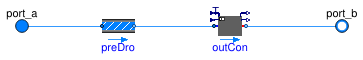
Base class for model for an ideal heater, cooler, humidifier or dehumidifier with a prescribed outlet conditions.
Models that extend this model need to configure the instance outCon
and connect its input signals, in they are enabled.
Extends from Buildings.Fluid.Interfaces.PartialTwoPortInterface (Partial model with two ports and declaration of quantities that are used by many models), Buildings.Fluid.Interfaces.TwoPortFlowResistanceParameters (Parameters for flow resistance for models with two ports).
Parameters
| Type | Name | Default | Description |
|---|---|---|---|
| replaceable package Medium | PartialMedium | Medium in the component | |
| Nominal condition | |||
| MassFlowRate | m_flow_nominal | Nominal mass flow rate [kg/s] | |
| PressureDifference | dp_nominal | Pressure difference [Pa] | |
| Assumptions | |||
| Boolean | allowFlowReversal | true | = false to simplify equations, assuming, but not enforcing, no flow reversal |
| Advanced | |||
| MassFlowRate | m_flow_small | 1E-4*abs(m_flow_nominal) | Small mass flow rate for regularization of zero flow [kg/s] |
| Diagnostics | |||
| Boolean | show_T | false | = true, if actual temperature at port is computed |
| Flow resistance | |||
| Boolean | computeFlowResistance | (abs(dp_nominal) > Modelica.... | =true, compute flow resistance. Set to false to assume no friction |
| Boolean | from_dp | false | = true, use m_flow = f(dp) else dp = f(m_flow) |
| Boolean | linearizeFlowResistance | false | = true, use linear relation between m_flow and dp for any flow rate |
| Real | deltaM | 0.1 | Fraction of nominal flow rate where flow transitions to laminar |
| Dynamics | |||
| Conservation equations | |||
| Dynamics | energyDynamics | Modelica.Fluid.Types.Dynamic... | Type of energy balance: dynamic (3 initialization options) or steady state |
| Time | tau | 10 | Time constant at nominal flow rate (used if energyDynamics not equal Modelica.Fluid.Types.Dynamics.SteadyState) [s] |
Connectors
| Type | Name | Description |
|---|---|---|
| FluidPort_a | port_a | Fluid connector a (positive design flow direction is from port_a to port_b) |
| FluidPort_b | port_b | Fluid connector b (positive design flow direction is from port_a to port_b) |
Modelica definition
 Buildings.Fluid.HeatExchangers.BaseClasses.PipeManifoldFixedResistance
Pipe manifold for a heat exchanger connection
Information
Pipe manifold with a fixed flow resistance.
This model is composed of a pressure drop calculation, and
a flow distributor. The flow distributor distributes the
mass flow rate equally to each instance of port_b,
without having to compute a pressure drop in each flow leg.
Note: It is important that there is an equal pressure drop in each flow leg between this model, and the model that collects the flows. Otherwise, no solution may exist, and therefore the simulation may stop with an error.
Extends from PartialPipeManifold (Partial pipe manifold for a heat exchanger).
Parameters
| Type | Name | Default | Description |
|---|---|---|---|
| replaceable package Medium | PartialMedium | Medium in the component | |
| Integer | nPipPar | Number of parallel pipes in each register | |
| Boolean | use_dh | false | Set to true to specify hydraulic diameter |
| Length | dh | 0.025 | Hydraulic diameter for each pipe [m] |
| Real | ReC | 4000 | Reynolds number where transition to turbulence starts |
| Real | deltaM | 0.3 | Fraction of nominal mass flow rate where transition to turbulent occurs |
| Initialization | |||
| MassFlowRate | mStart_flow_a | Guess value for mass flow rate at port_a [kg/s] | |
| Nominal Condition | |||
| MassFlowRate | m_flow_nominal | Mass flow rate at port_a [kg/s] | |
| PressureDifference | dp_nominal | Pressure drop [Pa] | |
| Assumptions | |||
| Boolean | allowFlowReversal | true | = true to allow flow reversal, false restricts to design direction (port_a -> port_b) |
| Advanced | |||
| Boolean | linearized | false | = true, use linear relation between m_flow and dp for any flow rate |
| Boolean | from_dp | false | = true, use m_flow = f(dp) else dp = f(m_flow) |
Connectors
| Type | Name | Description |
|---|---|---|
| FluidPort_a | port_a | Fluid connector a for medium (positive design flow direction is from port_a to port_b) |
| FluidPort_b | port_b[nPipPar] | Fluid connector b for medium (positive design flow direction is from port_a to port_b) |
Modelica definition
Buildings.Fluid.HeatExchangers.BaseClasses.PipeManifoldFlowDistributor
Manifold for heat exchanger register that distributes the mass flow rate equally
Information
This model distributes the mass flow rates equally between all instances
of port_b.
This model connects the flows between the ports without
modeling flow friction.
The model assigns an equal mass flow rate to each element of
port_b.
The model is used in conjunction with
a manifold that
is added to the other side of the heat exchanger registers.
Note: It is important that there is an equal pressure drop in each flow leg between this model, and the model that collects the flows. Otherwise, no solution may exist, and therefore the simulation may stop with an error.
Extends from PartialPipeManifold (Partial pipe manifold for a heat exchanger).
Parameters
| Type | Name | Default | Description |
|---|---|---|---|
| replaceable package Medium | PartialMedium | Medium in the component | |
| Integer | nPipPar | Number of parallel pipes in each register | |
| Initialization | |||
| MassFlowRate | mStart_flow_a | Guess value for mass flow rate at port_a [kg/s] | |
| Assumptions | |||
| Boolean | allowFlowReversal | true | = true to allow flow reversal, false restricts to design direction (port_a -> port_b) |
Connectors
| Type | Name | Description |
|---|---|---|
| FluidPort_a | port_a | Fluid connector a for medium (positive design flow direction is from port_a to port_b) |
| FluidPort_b | port_b[nPipPar] | Fluid connector b for medium (positive design flow direction is from port_a to port_b) |
Modelica definition
Buildings.Fluid.HeatExchangers.BaseClasses.PipeManifoldNoResistance
Manifold for heat exchanger register
Information
Pipe manifold without flow resistance.
This model connects the flows between the ports without modeling flow friction. The model is used in conjunction with a manifold which contains pressure drop elements and that is added to the other side of the heat exchanger registers.
Extends from PartialPipeManifold (Partial pipe manifold for a heat exchanger).
Parameters
| Type | Name | Default | Description |
|---|---|---|---|
| replaceable package Medium | PartialMedium | Medium in the component | |
| Integer | nPipPar | Number of parallel pipes in each register | |
| Boolean | connectAllPressures | true | |
| Initialization | |||
| MassFlowRate | mStart_flow_a | Guess value for mass flow rate at port_a [kg/s] | |
| Assumptions | |||
| Boolean | allowFlowReversal | true | = true to allow flow reversal, false restricts to design direction (port_a -> port_b) |
Connectors
| Type | Name | Description |
|---|---|---|
| FluidPort_a | port_a | Fluid connector a for medium (positive design flow direction is from port_a to port_b) |
| FluidPort_b | port_b[nPipPar] | Fluid connector b for medium (positive design flow direction is from port_a to port_b) |
Modelica definition
 Buildings.Fluid.HeatExchangers.BaseClasses.RayleighNumber
Calculates the Rayleigh number for a given fluid and characteristic length
Information
This model calculates the rayleigh number for a given fluid and characteristic length. It is calculated using Eq 9.25 in Incropera and DeWitt (1996). The equation is:
RaL = GrL Pr (g B (TS - TF) L3) /(ν*α)
where:
RaL is the Rayleigh number, GrL is the Grashof number, Pr
is the Prandtl number, g is gravity, B is the isobaric expansion coefficient,
TS is the temperature of the surface, TF is the temperature of the
fluid, L is the characteristic length, ν is the kinematic viscosity and α
is the thermal diffusivity.
This model is currently only used in natural convection calculations for water. As a result, the calculations reference functions to identify properties of water instead of a medium model.
References
Fundamentals of Heat and Mass Transfer (Fourth Edition), Frank Incropera and David DeWitt, John Wiley and Sons, 1996
Extends from Modelica.Blocks.Icons.Block (Basic graphical layout of input/output block).
Parameters
| Type | Name | Default | Description |
|---|---|---|---|
| replaceable package Medium | Modelica.Media.Interfaces.Pa... | Fluid medium model | |
| Diameter | ChaLen | Characteristic length [m] | |
Connectors
| Type | Name | Description |
|---|---|---|
| replaceable package Medium | Fluid medium model | |
| input RealInput | TSur | Surface temperature of the HX [K] |
| output RealOutput | Ra | Rayleigh number |
| output RealOutput | Pr | Prandlt number |
| input RealInput | TFlu | Temperature of the surrounding fluid [K] |
Modelica definition
 Buildings.Fluid.HeatExchangers.BaseClasses.WetCoilDryRegime
Fully dry coil model
Information
This model implements the calculation for a 100% dry coil.
See Buildings.Fluid.HeatExchangers.DryCoilEffectivenessNTU for documentation.
Parameters
| Type | Name | Default | Description |
|---|---|---|---|
| Real | delta | 1E-3 | Small value used for smoothing |
Modelica definition
 Buildings.Fluid.HeatExchangers.BaseClasses.WetCoilDryWetRegime
Model implementing the switching algorithm of the TK-fuzzy model for cooling coil application
Information
This model implements the switching algorithm for the dry and wet regime.
The switching criteria for (counter-flow) cooling coil modes are as follows.
R1: If the coil surface temperature at the air inlet is lower than the dew-point temperature at the inlet to the coil, then the cooling coil surface is fully-wet.
R2: If the surface temperature at the air outlet section is higher than the dew-point temperature of the air at the inlet, then the cooling coil surface is fully-dry.
At each point of a simulation time step, the fuzzy-modeling approach determines the weights for R1 and R2 respectively (namely μFW and μFD) from the dew-point and coil surface temperatures.
It calculates total and sensible heat transfer rates according to the weights as follows.
Q̇tot=μFD Q̇tot,FD+μFW Qtot,FW
Q̇sen=μFD Q̇sen,FD+μFW Qsen,FW
The fuzzy-modeling ensures μFW + μFD = 1, μFW >=0 and μFD >=0, which means the fuzzy model outcomes of Q̇sen and Q̇tot are always convex combinations of heat transfer rates for fully-dry and fully-wet modes and therefore are always bounded by them.
The modeling approach also results in n-th order differentiable model depending on the selection of the underlying membership functions. This cooling coil model is once continuously differentiable at the mode switches.
Parameters
| Type | Name | Default | Description |
|---|---|---|---|
| Nominal condition | |||
| MassFlowRate | mWat_flow_nominal | Nominal mass flow rate for water [kg/s] | |
| MassFlowRate | mAir_flow_nominal | Nominal mass flow rate for air [kg/s] | |
Connectors
| Type | Name | Description |
|---|---|---|
| input RealInput | UAWat | Product of heat transfer coefficient times area for water side [W/K] |
| input RealInput | mWat_flow | Mass flow rate for water [kg/s] |
| input RealInput | cpWat | Inlet water temperature [J/(kg.K)] |
| input RealInput | TWatIn | Inlet water temperature [K] |
| input RealInput | UAAir | Product of heat transfer coefficient times area for air side [W/K] |
| input RealInput | mAir_flow | Mass flow rate for air [kg/s] |
| input RealInput | cpAir | Inlet specific heat capacity (at constant pressure) [J/(kg.K)] |
| input RealInput | TAirIn | Inlet air temperature [K] |
| input RealInput | hAirIn | Inlet air enthalpy [J/kg] |
| input RealInput | pAir | Inlet air absolute pressure [Pa] |
| input RealInput | X_wAirIn | Mass fraction of water in inlet air (kg water/kg total air) [1] |
| output RealOutput | QTot_flow | Total heat transfer from water into air, negative for cooling [W] |
| output RealOutput | QSen_flow | Sensible heat transfer from water into air, negative for cooling [W] |
| output RealOutput | mCon_flow | Mass flow of the condensate, negative for dehumidification [kg/s] |
Modelica definition
 Buildings.Fluid.HeatExchangers.BaseClasses.WetCoilUARated
Model that calculates the UA-value from cooling coil data at rated conditions.
Information
This model calculates the overall heat transfer coefficient, i.e., UA-value, from cooling coil data at rated conditions.
The main limitation of the current implementation is that the rated conditions should correspond to a fully-dry or a fully-wet coil regime. The modeling uncertainty yielded by partially-wet rated conditions has not been assessed yet.
Parameters
| Type | Name | Default | Description |
|---|---|---|---|
| replaceable package MediumA | Buildings.Media.Air | Air-side medium | |
| replaceable package MediumW | Buildings.Media.Water | Water-side medium | |
| HeatFlowRate | QTot_flow | Nominal heat flow rate (positive for heat transfer from 1 to 2) [W] | |
| Temperature | TAirIn | Air inlet temperature at a rated condition [K] | |
| MassFraction | X_wAirIn | Mass fraction of water in inlet air at a rated condition [1] | |
| Temperature | TWatIn | Water inlet temperature at a rated condition [K] | |
| MassFlowRate | mAir_flow | Air mass flow rate at a rated condition [kg/s] | |
| MassFlowRate | mWat_flow | Water mass flow rate at a rated condition [kg/s] | |
| ThermalConductance | UA | Overall heat transfer coefficient for a fully dry condition [W/K] | |
| Real | r_nominal | Ratio between air-side and water-side convective heat transfer at nominal condition | |
| Nominal thermal performance | |||
| Boolean | use_Q_flow_nominal | false | Set to true to specify Q_flow_nominal and inlet conditions, or to false to specify UA_nominal |
Connectors
| Type | Name | Description |
|---|---|---|
| replaceable package MediumA | Air-side medium | |
| replaceable package MediumW | Water-side medium | |
Modelica definition
 Buildings.Fluid.HeatExchangers.BaseClasses.WetCoilWetRegime
Fully wet coil model using esilon_C.mo function
Information
This model implements the calculation for a 100% wet coil.
The equations from Braun (1988) and Mitchell and Braun (2012a and b), which are essentially the extension of the ε-NTU approach to simultaneous sensible and latent heat transfer, are utilized.
The mathematical equations are analogous to that of the sensible heat exchanger. However, the key distinction is that the heat transfer is driven by an enthalpy difference not by an temperature difference. This change in the driving potential results in re-defining capacitances and heat transfer coefficients accordingly.
The total heat transfer rate is expressed as
Qtot=ε* C*min (hair,in-hsat(Twat,in)),
where ε*=f(Cr*,NTU*) and f is the same ε-NTU relationships (depending on the heat exchanger configuration) for the sensible heat exchanger.
hair,in and hsat(Twat,in) are the specific enthalpies of the incoming moist air and saturated moist air at the water inlet temperature.
The capacitances of water and air streams are defined as
C*air=mair and C*wat=mwatcp,wat/csat,
where csat is an specific heat capacity, which indicates the sensitivity of the enthalpy of the staturated moist air w.r.t. the temperature, and is defined here as csat=(hsat(Twat,out)-hsat(Twat,in)) /(Twat,out-Twat,in).
The capacitance ratio and minimum capacitance are naturally defined as
Cr*=min(C*air,C*wat)/max(C*air,C*wat) and C*min=min(C*air,C*wat).
The number of transfer unit for the wet-coil is defined as NTU*=UA*/C*min, where
UA*=1/(1/(UAair/cp,air)+1/(UAwat/csat).
References
Braun, James E. 1988. "Methodologies for the Design and Control of Central Cooling Plants". PhD Thesis. University of Wisconsin - Madison. Available online.
Mitchell, John W., and James E. Braun. 2012a. Principles of heating, ventilation, and air conditioning in buildings. Hoboken, N.J.: Wiley.
Mitchell, John W., and James E. Braun. 2012b. "Supplementary Material Chapter 2: Heat Exchangers for Cooling Applications". Excerpt from Principles of heating, ventilation, and air conditioning in buildings. Hoboken, N.J.: Wiley. Available online.
Parameters
| Type | Name | Default | Description |
|---|---|---|---|
| Real | delta | 1E-3 | Small value used for smoothing |
| Real | tau | 6*60 | Time constant for state estimation: introduced to avoid the algebraic loop of the wet coil equations |
Modelica definition
Buildings.Fluid.HeatExchangers.BaseClasses.determineWaterIndex
Determine the index of water in a 2-component medium model
Information
Given an array of strings representing substance names, this function returns the integer index of the substance named "water" (case-insensitive).
This function is useful to automate lookup up the index of water within a media so as to avoid hard-coding or guessing what the index will be. Typically, this function would be run once at initialization time.
Inputs
| Type | Name | Default | Description |
|---|---|---|---|
| String | substanceNames[:] | Names of substances of media |
Outputs
| Type | Name | Description |
|---|---|---|
| Integer | idxWat | Index of water |
Modelica definition
Buildings.Fluid.HeatExchangers.BaseClasses.dynamicViscosityWater
Returns the dynamic viscosity for water
Information
This function is used to identify the dynamic viscosity of water at a given temperature. The function used is a fourth order polynomial fit to data from Incropera and Dewitt (1996).
References
Fundamentals of Heat and Mass Transfer (Fourth Edition), Frank Incropera and David P. Dewitt, John Wiley & Sons, 1996
Inputs
| Type | Name | Default | Description |
|---|---|---|---|
| Temperature | T | Thermodynamic state record [K] |
Outputs
| Type | Name | Description |
|---|---|---|
| DynamicViscosity | mu | Dynamic viscosity [Pa.s] |
Modelica definition
Buildings.Fluid.HeatExchangers.BaseClasses.epsilon_C
Computes heat exchanger effectiveness for given capacity flow rates and heat exchanger flow regime
Information
This function computes the heat exchanger effectiveness, the Number of Transfer Units, and the capacity flow ratio for given capacity flow rates.
The implementation allows for zero flow rate.
As CMin_flow crosses delta*CMin_flow_nominal from above,
the Number of Transfer Units and the heat exchanger effectiveness go to zero.
The different options for the flow regime are declared in Buildings.Fluid.Types.HeatExchangerFlowRegime.
Inputs
| Type | Name | Default | Description |
|---|---|---|---|
| ThermalConductance | UA | UA value [W/K] | |
| ThermalConductance | C1_flow | Enthalpy flow rate medium 1 [W/K] | |
| ThermalConductance | C2_flow | Enthalpy flow rate medium 2 [W/K] | |
| Integer | flowRegime | Heat exchanger flow regime, see Buildings.Fluid.Types.HeatExchangerFlowRegime | |
| ThermalConductance | CMin_flow_nominal | Minimum enthalpy flow rate at nominal condition [W/K] | |
| ThermalConductance | CMax_flow_nominal | Maximum enthalpy flow rate at nominal condition [W/K] | |
| Real | delta | 1E-3 | Small value used for smoothing |
Outputs
| Type | Name | Description |
|---|---|---|
| Real | eps | Heat exchanger effectiveness |
Modelica definition
Buildings.Fluid.HeatExchangers.BaseClasses.epsilon_ntuZ
Computes heat exchanger effectiveness for given number of transfer units and heat exchanger flow regime
Information
This function computes the heat exchanger effectiveness for a given number of transfer units, capacity flow ratio and heat exchanger flow regime. The different options for the flow regime are declared in Buildings.Fluid.Types.HeatExchangerFlowRegime.
Inputs
| Type | Name | Default | Description |
|---|---|---|---|
| Real | NTU | Number of transfer units | |
| Real | Z | Ratio of capacity flow rate (CMin/CMax) | |
| Integer | flowRegime | Heat exchanger flow regime, see Buildings.Fluid.Types.HeatExchangerFlowRegime |
Outputs
| Type | Name | Description |
|---|---|---|
| Real | eps | Heat exchanger effectiveness |
Modelica definition
Buildings.Fluid.HeatExchangers.BaseClasses.isobaricExpansionCoefficientWater
Returns the isobaric expansion coefficient for water
Information
This function is used to identify the isobaric expansion coefficient of water at a given temperature. The function used is a fourth order polynomial fit to data from Incropera and Dewitt (1996).
References
Fundamentals of Heat and Mass Transfer (Fourth Edition), Frank Incropera and David P. Dewitt, John Wiley & Sons, 1996
Inputs
| Type | Name | Default | Description |
|---|---|---|---|
| Temperature | T | Thermodynamic state record [K] |
Outputs
| Type | Name | Description |
|---|---|---|
| Real | beta | Dynamic viscosity [1/K] |
Modelica definition
Buildings.Fluid.HeatExchangers.BaseClasses.lmtd
Log-mean temperature difference
Information
This function computes the log mean temperature difference of a heat exchanger.
Note that the implementation requires the temperature differences Ta1 - Tb2 and Tb1 - Ta2 to be not equal to each other.
Inputs
| Type | Name | Default | Description |
|---|---|---|---|
| Temperature | T_a1 | Temperature at port a1 [K] | |
| Temperature | T_b1 | Temperature at port b1 [K] | |
| Temperature | T_a2 | Temperature at port a2 [K] | |
| Temperature | T_b2 | Temperature at port b2 [K] |
Outputs
| Type | Name | Description |
|---|---|---|
| TemperatureDifference | lmtd | Log-mean temperature difference [K] |
Modelica definition
Buildings.Fluid.HeatExchangers.BaseClasses.ntu_epsilonZ
Computes number of transfer units for given heat exchanger effectiveness and heat exchanger flow regime
Information
This function computes the number of transfer units for a given heat exchanger effectiveness, capacity flow ratio and heat exchanger flow regime. The different options for the flow regime are declared in Buildings.Fluid.Types.HeatExchangerFlowRegime.
Note that for the flow regime CrossFlowUnmixed, computing the
function requires the numerical solution of an equation in one variable.
This is handled internally and not exposed to the global solver.
Inputs
| Type | Name | Default | Description |
|---|---|---|---|
| Real | eps | Heat exchanger effectiveness | |
| Real | Z | Ratio of capacity flow rate (CMin/CMax) | |
| Integer | flowRegime | Heat exchanger flow regime |
Outputs
| Type | Name | Description |
|---|---|---|
| Real | NTU | Number of transfer units |
Modelica definition
Buildings.Fluid.HeatExchangers.BaseClasses.prandtlNumberWater
Returns the Prandtl number for water
Information
This function is used to identify the Prandtl number of water at a given temperature. The function used is a fourth order polynomial fit to data from Incropera and Dewitt (1996).
References
Fundamentals of Heat and Mass Transfer (Fourth Edition), Frank Incropera and David P. Dewitt, John Wiley & Sons, 1996
Inputs
| Type | Name | Default | Description |
|---|---|---|---|
| Temperature | T | Thermodynamic state record [K] |
Outputs
| Type | Name | Description |
|---|---|---|
| Real | Pr | Prandtl number |