
Buildings.Fluid.DataCenters.Racks.Air
Package with models for air-cooled IT racks
Information
This package contains models for air-cooled IT racks. For air-cooled IT racks with rear door heat exchangers, see the package Buildings.Fluid.DataCenters.Racks.Hybrid.
Extends from Modelica.Icons.VariantsPackage (Icon for package containing variants).
Package Content
| Name | Description |
|---|---|
 Rack_P |
Model of an air-cooled rack, and utilization is input |
 Data |
Package with data records for racks |
 Examples |
Collection of models that illustrate model use and test models |
 Buildings.Fluid.DataCenters.Racks.Air.Rack_P
Model of an air-cooled rack, and utilization is input
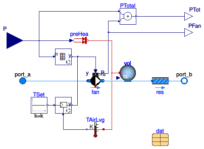
Information
Model of an air-cooled IT rack.
Electrical and fluid characterization
The model takes as a parameter the thermal design power (TDB) P_nominal
and as an input the utilization u.
The heat added to the coolant fluid is then calculated as
Q_flow = u P_nominal.
The fluid outlet temperature is computed using a first order delay to mimic
the transient effect. This first order delay is characterized by the user-configurable
time constant tau, set by default to tau=2 seconds.
For exact transient response, this value should be identified based on measurements.
To compute the pressure drop, the model uses Buildings.Fluid.FixedResistances.PressureDrop. Therefore, the mass flow rate and pressure drop are related as
m_flow ⁄ m_flow_nominal = (dp ⁄ dp_nominal)m,
where
m_flow_nominal is a parameter for the design flow rate,
dp is the pressure difference between inlet and outlet,
dp_nominal is a parameter for the design pressure difference, and
m is a parameter for the flow exponent.
Because the pressure drop of the rack is typically no a known design quantity, the model computes it internally based on the fan power consumption and the fan efficiency.
Fan
The model has a built-in fan which uses a constant total efficiency, specified through the
parameter dat.eta_nominal.
The fan has a PI controller that maintains a temperature difference across
the rack equal to the parameter dTSet.
Implementation
The implementation uses a fan model with prescribed speed, and, as explained above, it computes a flow resistance which is then used in the simulations. This implementation is used to allow use of this model with active rear door heat exchangers. As active rear-door heat exchangers also have a fan, in such a configuration there will be two fans in series. Prescribing the mass flow rate instead of the fan may give in this situation an overspecified system of equations. Thefore, rack model and rear-door heat exchangers use the fan model Buildings.Fluid.DataCenters.Racks.BaseClasses.ControlledFan.
Extends from Buildings.Fluid.DataCenters.Racks.BaseClasses.PartialRack (Partial model of an IT rack, with utilization as input).
Parameters
| Type | Name | Default | Description |
|---|---|---|---|
| replaceable package Medium | PartialMedium | Medium in the component | |
| Fan controller | |||
| Strategy | fanControl | Buildings.Fluid.DataCenters.... | Type of fan control strategy |
| Real | fanSpeed[:, :] | [0.0, 0.0; 1.0, 1.0] | Load and fan speed matrix (1st column normalized IT load, 2nd fan speed), e.g., fanSpeed=[0, 0; 0.5, 0.7; 1, 1]) |
| Temperature | TAirOut_set | dat.TOut_nominal | Set point temperature for rack outlet air [K] |
| Real | k | 1 | Gain of fan PI controller |
| Time | Ti | 60 | Integrator time constant of fan PI controller [s] |
| Assumptions | |||
| Boolean | allowFlowReversal | true | = false to simplify equations, assuming, but not enforcing, no flow reversal |
| Dynamics | |||
| Conservation equations | |||
| Dynamics | energyDynamics | Modelica.Fluid.Types.Dynamic... | Type of energy balance: dynamic (3 initialization options) or steady state |
| Time | tau | 2 | Time constant of fluid outlet temperature at nominal flow [s] |
| Initialization | |||
| Temperature | T_start | Medium.T_default | Start value of temperature [K] |
Connectors
| Type | Name | Description |
|---|---|---|
| FluidPort_a | port_a | Fluid connector a (positive design flow direction is from port_a to port_b) |
| FluidPort_b | port_b | Fluid connector b (positive design flow direction is from port_a to port_b) |
| input RealInput | P | Electrical power consumption [W] |
| output RealOutput | PTot | Electrical power consumed by IT and fan [W] |
| output RealOutput | PFan | Electrical power consumed by fan [W] |