Package with base classes
Information
This package contains base classes that are used to construct
the main plant controller.
Those include an interface class for the controller as well
as blocks that implement the sequence of operation for each
component of the plant.
Extends from Modelica.Icons.BasesPackage (Icon for packages containing base classes).
Package Content
| Name |
Description |
 CoolingTowerLoop CoolingTowerLoop
|
Cooling tower loop control |
 Delay Delay
|
Delay input |
 DirectHeatRecovery DirectHeatRecovery
|
Block controlling HRC in direct heat recovery mode |
 HoursToNextWarmup HoursToNextWarmup
|
Number of hours to next warmup period |
 IntegerArrayHold IntegerArrayHold
|
Block that holds the value of an integer array for a given time |
 ModeCondenserLoop ModeCondenserLoop
|
Block that determines the condenser loop mode |
 ModeHeatRecoveryChiller ModeHeatRecoveryChiller
|
Block that computes the cascading cooling and direct HR switchover signals |
 PartialController PartialController
|
Interface class for plant controller |
 StageIndex StageIndex
|
Block that computes the stage index out of staging signals |
 StagingCapacity StagingCapacity
|
Total capacity at current stages times stage-up PLR limit |
 StagingPlant StagingPlant
|
Block that computes plant stage and command signals for chillers and HRC |
 StagingPump StagingPump
|
Pump staging |
| TankChargeFraction
|
Tank charge fraction |
| TankChargeFractionRate
|
Rate of change of the tank charge fraction |
 TankCycle TankCycle
|
Block that determines the tank cycle flag |
 ValveCondenserEvaporator ValveCondenserEvaporator
|
Controller for chiller and HRC condenser and evaporator valves |
 Validation Validation
|
Package with validation models |
Cooling tower loop control
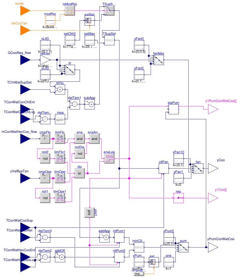
Information
This block implements the control logic for the CT pumps and
CT fans.
CT supply temperature setpoint
When Heat Rejection mode is enabled, the setpoint is equal to
min(25 °C, TChiWatSupSet + dTLif - dTConWat - dTHexCoo_nominal), where
TChiWatSupSet is the CHW supply temperature setpoint,
dTLif is the target chiller lift (see below),
dTConWat is the chiller condenser Delta-T averaged over
a 5-minute moving window, and
dTHexCoo_nominal is the design heat exchanger approach.
The target chiller lift is reset from the minimum chiller lift
to the design chiller lift when the plant required cooling capacity
varies from 10 % to 100 % of the design value.
In any other mode the setpoint is equal to the minimum setpoint value
of the active tank cycle minus the design heat exchanger approach.
CT pumps
The lead pump is enabled whenever the TES tank bypass valve commanded
position is lower than 1 for 1 min and the
CW mass flow rate through the secondary side of the cooling heat exchanger
is higher than 2.5 % of design condition for 1 min.
The lead pump is disabled whenever the TES tank bypass valve commanded
position is equal to 1 for 1 min or the
CW mass flow rate through the secondary side of the cooling heat exchanger
is lower than 2.5 % of design condition for 5 min.
The lag pump is enabled whenever the pump speed command (common to all pumps)
is higher than 80 % for 5 min.
The lag pump is disabled whenever the pump speed command
is lower than 80 % for 5 min or the lead pump
is disabled.
The pump speed command is the lower of that output by two loops, each loop
being enabled whenever any pump is proven on.
The first loop maintains the heat exchanger leaving CW
temperature on plant side at setpoint.
The setpoint is equal to the CT supply temperature setpoint plus
the design HX approach.
The second loop maintains the Delta-T across the primary side (CT loop)
of the HX at a setpoint equal to the Delta-T across the secondary
side (plant side) of the HX minus 1 K.
(This loop keeps the primary and secondary HX flow rates close to each other
and prevents pump speed runaway when target CT supply temperature setpoint
cannot be met.)
The output of each loop is mapped to the minimum pump speed at 80 %
to 100 % at 100 %.
The minimum pump speed is provided as a parameter for each pump stage since
different speeds are required for each stage to maintain minimum tower flow.
CT fans
When any of the CT pumps is commanded On, a control loop maintains the
tower water supply temperature at setpoint by resetting the tower fan speed
from 0 % to a maximum value varying between 70 %
and 100 % when the plant required cooling capacity
varies from 0 % to 50 % of the design value.
Otherwise, the loop is disabled and its output set to 0 %.
Note that the fan cycling On and Off is implicitly modeled
in the cooling tower component which uses a low limit of the control signal
to switch to a free convection regime at zero fan power.
Parameters
| Type | Name | Default | Description |
|---|
| Real | mConWatHexCoo_flow_nominal | | Design total CW mass flow rate through condenser barrels (all units) [kg/s] |
| Integer | nCoo | | Number of cooling tower cells operating at design conditions |
| Integer | nPumConWatCoo | | Number of CW pumps serving cooling towers at design conditions |
| Real | QChiWat_flow_nominal | | Design plant cooling heat flow rate (all units) [W] |
| Real | dTLifChi_min | | Minimum chiller lift at minimum load [K] |
| Real | dTLifChi_nominal | | Design chiller lift [K] |
| Real | TTanSet[2, 2] | | Tank temperature setpoints: 2 cycles with 2 setpoints [K] |
| Real | dTHexCoo_nominal | | Design heat exchanger approach [K] |
| Real | yPumConWatCoo_min[nPumConWatCoo] | {0.2/i for i in 1:nPumConWat... | Tower pump speed needed to maintain minimum tower flow (each pump stage) [1] |
Connectors
| Type | Name | Description |
|---|
| input IntegerInput | mode | Condenser loop operating mode |
| input IntegerInput | idxCycTan | Index of active tank cycle |
| input RealInput | TConWatCooSup | Cooling tower loop CW supply temperature [K] |
| input RealInput | mConWatHexCoo_flow | CW mass flow rate through secondary side of HX [kg/s] |
| input RealInput | QCooReq_flow | Plant required cooling capacity (>0) [W] |
| input RealInput | TConWatConChiEnt | Chiller and HRC entering CW temperature [K] |
| input RealInput | TConWatConChiLvg | Chiller and HRC leaving CW temperature [K] |
| input RealInput | TChiWatSupSet | CHW supply temperature setpoint [K] |
| input RealInput | TConWatCooRet | Cooling tower loop CW return temperature [K] |
| input RealInput | yValBypTan | TES tank bypass valve commanded position [1] |
| input RealInput | TConWatHexCooEnt | HX entering CW temperature [K] |
| input RealInput | TConWatHexCooLvg | HX leaving CW temperature [K] |
| output BooleanOutput | y1PumConWatCoo[nPumConWatCoo] | Cooling tower pump Start command |
| output RealOutput | yCoo | Cooling tower fan speed command |
| output RealOutput | yPumConWatCoo | Cooling tower pump speed command |
| output BooleanOutput | y1Coo[nCoo] | Cooling tower Start command |
Modelica definition
block CoolingTowerLoop
parameter Real mConWatHexCoo_flow_nominal(
final quantity="MassFlowRate",
final unit="kg/s")
;
parameter Integer nCoo(
final min=1, start=1)
;
parameter Integer nPumConWatCoo(
final min=1, start=1)
;
parameter Real QChiWat_flow_nominal(
final quantity="HeatFlowRate",
final unit="W")
;
parameter Real dTLifChi_min(
final quantity="TemperatureDifference",
final unit="K")
;
parameter Real dTLifChi_nominal(
final quantity="TemperatureDifference",
final unit="K")
;
parameter Real TTanSet[2, 2](
each final quantity="ThermodynamicTemperature",
each final unit="K",
each displayUnit="degC")
;
parameter Real dTHexCoo_nominal(
final quantity="TemperatureDifference",
final unit="K")
;
parameter Real yPumConWatCoo_min[nPumConWatCoo](
each final unit="1")= {0.2/i
for i
in 1:nPumConWatCoo}
;
Buildings.Controls.OBC.CDL.Interfaces.IntegerInput mode(
final min=Buildings.DHC.Plants.Combined.Controls.ModeCondenserLoop.tankCharge,
final max=Buildings.DHC.Plants.Combined.Controls.ModeCondenserLoop.heatRejection)
;
Buildings.Controls.OBC.CDL.Interfaces.IntegerInput idxCycTan(
final min=1,
final max=2)
;
Buildings.Controls.OBC.CDL.Interfaces.RealInput TConWatCooSup(
final unit="K",
displayUnit="degC")
;
Buildings.Controls.OBC.CDL.Interfaces.RealInput mConWatHexCoo_flow(
final unit="kg/s")
;
Buildings.Controls.OBC.CDL.Interfaces.RealInput QCooReq_flow(
final unit="W")
;
Buildings.Controls.OBC.CDL.Interfaces.RealInput TConWatConChiEnt(
final unit="K",
displayUnit="degC")
;
Buildings.Controls.OBC.CDL.Interfaces.RealInput TConWatConChiLvg(
final unit="K",
displayUnit="degC")
;
Buildings.Controls.OBC.CDL.Interfaces.RealInput TChiWatSupSet(
final unit="K",
displayUnit="degC")
;
Buildings.Controls.OBC.CDL.Interfaces.RealInput TConWatCooRet(
final unit="K",
displayUnit="degC")
;
Buildings.Controls.OBC.CDL.Interfaces.RealInput yValBypTan(
final unit="1")
;
Buildings.Controls.OBC.CDL.Interfaces.RealInput TConWatHexCooEnt(
final unit="K",
displayUnit="degC")
;
Buildings.Controls.OBC.CDL.Interfaces.RealInput TConWatHexCooLvg(
final unit="K",
displayUnit="degC")
;
Buildings.Controls.OBC.CDL.Interfaces.BooleanOutput y1PumConWatCoo[nPumConWatCoo]
;
Buildings.Controls.OBC.CDL.Interfaces.RealOutput yCoo
;
Buildings.Controls.OBC.CDL.Interfaces.RealOutput yPumConWatCoo
;
Buildings.Controls.OBC.CDL.Interfaces.BooleanOutput y1Coo[nCoo]
;
Buildings.Controls.OBC.CDL.Reals.Subtract delTemCon
;
Buildings.Controls.OBC.CDL.Reals.MovingAverage mea(
delta=5*60)
;
Buildings.Controls.OBC.CDL.Reals.Subtract delTem1
;
Buildings.Controls.OBC.CDL.Reals.Add lifPlu
;
Buildings.Controls.OBC.CDL.Reals.AddParameter subApp(
final p=-dTHexCoo_nominal)
;
Buildings.Controls.OBC.CDL.Reals.Switch TSupSetUnb(
y(unit="K", displayUnit="degC"))
;
Buildings.Controls.OBC.CDL.Integers.Sources.Constant modRej(
final k=Buildings.DHC.Plants.Combined.Controls.ModeCondenserLoop.heatRejection)
;
Buildings.Controls.OBC.CDL.Integers.Equal isModRej
;
Buildings.Controls.OBC.CDL.Routing.RealExtractor extSet(
final nin=2)
;
Buildings.Controls.OBC.CDL.Reals.MultiplyByParameter ratDes(
final k=
abs(1/QChiWat_flow_nominal))
;
Buildings.Controls.OBC.CDL.Reals.Line lif
;
Buildings.Controls.OBC.CDL.Reals.Sources.Constant xLif[2](k={0.1,1})
;
Buildings.Controls.OBC.CDL.Reals.Sources.Constant yLif[2](
final k={dTLifChi_min,dTLifChi_nominal})
;
Buildings.DHC.Plants.Combined.Controls.BaseClasses.StagingPump staPum(
nPum=nPumConWatCoo,
have_flowCriterion=false,
yDow=0.4,
yUp=0.8)
;
Buildings.Controls.OBC.CDL.Reals.GreaterThreshold cmpFlo(
final t=0.025*mConWatHexCoo_flow_nominal,
final h=0.025*mConWatHexCoo_flow_nominal/2)
;
Buildings.Controls.OBC.CDL.Logical.Timer timFlo(
t=60)
;
Buildings.Controls.OBC.CDL.Logical.Timer timFlo1(
t=5*60)
;
Buildings.Controls.OBC.CDL.Reals.LessThreshold cmpOpe(
t=0.99,
h=0.005)
;
Buildings.Controls.OBC.CDL.Logical.Timer timOpe(t=60)
;
Buildings.Controls.OBC.CDL.Logical.Timer timOpe1(t=60)
;
Buildings.Controls.OBC.CDL.Logical.Not not1
;
Buildings.Controls.OBC.CDL.Logical.Or dis ;
Buildings.Controls.OBC.CDL.Logical.And ena ;
Buildings.Controls.OBC.CDL.Logical.Latch enaLea ;
Buildings.Controls.OBC.CDL.Reals.Subtract delTem2 ;
Buildings.Controls.OBC.CDL.Reals.Subtract delTem3 ;
Buildings.Controls.OBC.CDL.Reals.AddParameter addOff(
final p=-1)
;
Buildings.Controls.OBC.CDL.Reals.AddParameter addApp(
final p=dTHexCoo_nominal)
;
Buildings.Controls.OBC.Utilities.PIDWithEnable ctlPum1(
k=0.01,
Ti=60,
final reverseActing=false)
;
Buildings.Controls.OBC.Utilities.PIDWithEnable ctlPum2(
k=0.01,
Ti=60,
final reverseActing=false)
;
Buildings.Controls.OBC.CDL.Reals.Min minCtlPum
;
Buildings.Controls.OBC.CDL.Reals.Line pum
;
Buildings.Controls.OBC.CDL.Reals.Sources.Constant xPum[2](k={0,1})
;
Buildings.Controls.OBC.CDL.Reals.Sources.Constant one(
final k=1)
;
Buildings.Controls.OBC.CDL.Reals.Sources.Constant yPumMin[nPumConWatCoo](
final k=yPumConWatCoo_min)
;
Buildings.Controls.OBC.CDL.Routing.RealExtractor extYPumMin(
final nin=nPumConWatCoo)
;
Buildings.Controls.OBC.CDL.Reals.Line fanMax
;
Buildings.Controls.OBC.CDL.Reals.Sources.Constant xFan[2](k={0,0.5})
;
Buildings.Controls.OBC.CDL.Reals.Sources.Constant yFan[2](
final k={0.7,1.0})
;
Buildings.Controls.OBC.Utilities.PIDWithEnable ctlFan(
k=0.05,
Ti=60,
final reverseActing=false)
;
Buildings.Controls.OBC.CDL.Logical.Pre pre1
;
Buildings.Controls.OBC.CDL.Reals.Sources.Constant setMax(k=25 + 273.15)
;
Buildings.Controls.OBC.CDL.Reals.Min TSupSet(
y(unit="K", displayUnit="degC"))
;
Buildings.Controls.OBC.CDL.Reals.Line fan
;
Buildings.Controls.OBC.CDL.Reals.Sources.Constant xFan1[2](
k={0,1})
;
Buildings.Controls.OBC.CDL.Reals.Sources.Constant yFan1(
final k=0)
;
Buildings.Controls.OBC.CDL.Logical.Not not2
;
Buildings.Controls.OBC.CDL.Routing.BooleanScalarReplicator rep(
final nout=nCoo)
;
Buildings.Controls.OBC.CDL.Logical.Not notDis ;
Buildings.Controls.OBC.CDL.Logical.And enaAndNotDis
;
Buildings.Controls.OBC.CDL.Integers.Max comPum
;
Buildings.Controls.OBC.CDL.Integers.Sources.Constant conInt(
final k=1)
;
Buildings.Controls.OBC.CDL.Reals.Sources.Constant tanSet[2](
final k=TTanSet[:,1])
;
Buildings.Controls.OBC.CDL.Reals.Sources.Constant hexApp[2](
final k=
fill(dTHexCoo_nominal, 2))
;
Buildings.Controls.OBC.CDL.Reals.Subtract setOth3[2]
;
equation
connect(QCooReq_flow, ratDes.u);
connect(ratDes.y, lif.u);
connect(xLif[1].y, lif.x1);
connect(xLif[2].y, lif.x2);
connect(yLif[1].y, lif.f1);
connect(yLif[2].y, lif.f2);
connect(TConWatConChiLvg, delTemCon.u1);
connect(TConWatConChiEnt, delTemCon.u2);
connect(delTemCon.y, mea.u);
connect(lif.y, lifPlu.u1);
connect(TChiWatSupSet, lifPlu.u2);
connect(lifPlu.y, delTem1.u1);
connect(mea.y, delTem1.u2);
connect(delTem1.y,subApp. u);
connect(mode, isModRej.u1);
connect(modRej.y, isModRej.u2);
connect(isModRej.y, TSupSetUnb.u2);
connect(subApp.y, TSupSetUnb.u1);
connect(extSet.y, TSupSetUnb.u3);
connect(mConWatHexCoo_flow, cmpFlo.u);
connect(cmpFlo.y, timFlo.u);
connect(yValBypTan, cmpOpe.u);
connect(not1.y, timOpe1.u);
connect(cmpOpe.y, timOpe.u);
connect(cmpOpe.y, not1.u);
connect(timFlo.passed, ena.u1);
connect(timOpe.passed, ena.u2);
connect(timFlo1.passed, dis.u1);
connect(timOpe1.passed, dis.u2);
connect(dis.y,enaLea. clr);
connect(enaLea.y, staPum.y1Ena);
connect(TConWatCooRet, delTem3.u1);
connect(TConWatCooSup, delTem3.u2);
connect(TConWatHexCooEnt, delTem2.u1);
connect(delTem2.y, addOff.u);
connect(addApp.y, ctlPum1.u_s);
connect(delTem3.y, ctlPum2.u_m);
connect(addOff.y, ctlPum2.u_s);
connect(ctlPum1.y, minCtlPum.u1);
connect(ctlPum2.y, minCtlPum.u2);
connect(xPum[1].y, pum.x1);
connect(xPum[2].y, pum.x2);
connect(pum.y, yPumConWatCoo);
connect(one.y, pum.f2);
connect(minCtlPum.y, pum.u);
connect(idxCycTan,extSet. index);
connect(yPumMin.y, extYPumMin.u);
connect(extYPumMin.y, pum.f1);
connect(xFan[1].y, fanMax.x1);
connect(xFan[2].y, fanMax.x2);
connect(yFan[1].y, fanMax.f1);
connect(yFan[2].y, fanMax.f2);
connect(ratDes.y, fanMax.u);
connect(enaLea.y, pre1.u);
connect(TConWatCooSup, ctlFan.u_m);
connect(pum.y, staPum.y);
connect(pre1.y, ctlPum1.uEna);
connect(pre1.y, ctlPum2.uEna);
connect(staPum.y1, y1PumConWatCoo);
connect(setMax.y, TSupSet.u2);
connect(TSupSetUnb.y, TSupSet.u1);
connect(TSupSet.y, ctlFan.u_s);
connect(TSupSet.y, addApp.u);
connect(TConWatHexCooLvg, delTem2.u2);
connect(TConWatHexCooLvg, ctlPum1.u_m);
connect(xFan1[1].y, fan.x1);
connect(xFan1[2].y, fan.x2);
connect(yFan1.y, fan.f1);
connect(ctlFan.y, fan.u);
connect(fan.y, yCoo);
connect(fanMax.y, fan.f2);
connect(enaLea.y, ctlFan.uEna);
connect(cmpFlo.y, not2.u);
connect(not2.y, timFlo1.u);
connect(rep.y, y1Coo);
connect(enaLea.y, rep.u);
connect(ena.y, enaAndNotDis.u1);
connect(notDis.y, enaAndNotDis.u2);
connect(enaAndNotDis.y, enaLea.u);
connect(dis.y, notDis.u);
connect(comPum.y, extYPumMin.index);
connect(staPum.nPumEna, comPum.u2);
connect(conInt.y, comPum.u1);
connect(tanSet.y, setOth3.u1);
connect(hexApp.y, setOth3.u2);
connect(setOth3.y, extSet.u);
end CoolingTowerLoop;
Delay input

Information
Returns u(time - delayTime) for time > time.start + delayTime
and u(time.start) for time ≤ time.start + delayTime.
Parameters
| Type | Name | Default | Description |
|---|
| Real | delayTime | | Delay time [s] |
| Real | delayMax | delayTime | Maximum delay time [s] |
Connectors
Modelica definition
Block controlling HRC in direct heat recovery mode
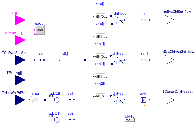
Information
In direct heat recovery mode, the HRC is internally controlled in heating mode
and tracks a HW supply temperature setpoint.
The CHW supply temperature setpoint is maintained by means of supervisory controls
that act on the evaporator flow rate and condenser entering water temperature as
described below.
A direct acting control loop runs for each HRC operating in direct heat recovery
mode.
Each loop is enabled with a bias of 50 % whenever the HRC
is commanded On and in direct heat recovery mode.
The loop is disabled with output set to 50 % otherwise.
The loop output is mapped as follows.
From 0 % to 33 % the evaporator flow setpoint of
cooling-only chillers is reset from 1.2 times its minimum value
to 1.2 times its design value.
From 33 % to 67 % the evaporator flow setpoint of
the HRC is reset from 1.2 times its minimum value
to 1.2 times its design value.
From 67 % to 100 % the HRC condenser entering
temperature setpoint is reset from THeaWatRet + 0.5 °C
to THeaWatRet - 15 °C.
Parameters
| Type | Name | Default | Description |
|---|
| CHW loop and cooling-only chillers |
| Integer | nChi | | Number of units operating at design conditions |
| Real | mChiWatChi_flow_nominal | | Chiller CHW design mass flow rate (value will be used for each unit) [kg/s] |
| Real | mChiWatChi_flow_min | | Chiller CHW minimum mass flow rate (value will be used for each unit) [kg/s] |
| HW loop and heat recovery chillers |
| Integer | nChiHea | | Number of units operating at design conditions |
| Real | mChiWatChiHea_flow_nominal | | HRC CHW design mass flow rate (value will be used for each unit) [kg/s] |
| Real | mChiWatChiHea_flow_min | | HRC CHW minimum mass flow rate (value will be used for each unit) [kg/s] |
| Control parameters |
| Real | k | 0.01 | Gain of controller |
| Real | Ti | 60 | Time constant of integrator block [s] |
| Real | y_reset | 0.5 | Value to which the controller output is reset if the boolean trigger has a rising edge |
| Real | y_neutral | 0.5 | Value to which the controller output is reset when the controller is disabled |
Connectors
| Type | Name | Description |
|---|
| input RealInput | TChiWatSupSet | CHW supply temperature setpoint [K] |
| input RealInput | TEvaLvg[nChiHea] | Evaporator barrel leaving temperature (each HRC) [K] |
| input BooleanInput | y1HeaCoo[nChiHea] | Direct HR command |
| input BooleanInput | y1[nChiHea] | On/Off command |
| output RealOutput | mEvaChiSet_flow | Chiller evaporator flow setpoint [kg/s] |
| output RealOutput | TConEntChiHeaSet | HRC condenser entering temperature setpoint [K] |
| input RealInput | THeaWatPriRet | Primary HW return temperature [K] |
| output RealOutput | mEvaChiHeaSet_flow | HRC evaporator flow setpoint [kg/s] |
Modelica definition
block DirectHeatRecovery
parameter Integer nChi(
final min=1, start=1)
;
parameter Integer nChiHea(
final min=1, start=1)
;
parameter Real mChiWatChi_flow_nominal(
final unit="kg/s",
final quantity="MassFlowRate")
;
parameter Real mChiWatChi_flow_min(
final unit="kg/s",
final quantity="MassFlowRate")
;
parameter Real mChiWatChiHea_flow_nominal(
final unit="kg/s",
final quantity="MassFlowRate")
;
parameter Real mChiWatChiHea_flow_min(
final unit="kg/s",
final quantity="MassFlowRate")
;
parameter Real k(min=0)=0.01
;
parameter Real Ti(
final unit="s",
final quantity="Time")=60
;
parameter Real y_reset=0.5
;
parameter Real y_neutral=0.5
;
Buildings.Controls.OBC.CDL.Interfaces.RealInput TChiWatSupSet(
final unit="K",
displayUnit="degC")
;
Buildings.Controls.OBC.CDL.Interfaces.RealInput TEvaLvg[nChiHea](
each final unit="K",
each displayUnit="degC")
;
Buildings.Controls.OBC.CDL.Interfaces.BooleanInput y1HeaCoo[nChiHea]
;
Buildings.Controls.OBC.CDL.Interfaces.BooleanInput y1[nChiHea]
;
Buildings.Controls.OBC.CDL.Interfaces.RealOutput mEvaChiSet_flow(
final unit="kg/s") ;
Buildings.Controls.OBC.CDL.Interfaces.RealOutput TConEntChiHeaSet(
final unit="K", displayUnit="degC")
;
Buildings.Controls.OBC.CDL.Interfaces.RealInput THeaWatPriRet(
final unit="K",
displayUnit="degC")
;
Buildings.Controls.OBC.CDL.Logical.And heaCooAndOn[nChiHea]
;
Buildings.Controls.OBC.CDL.Routing.RealScalarReplicator rep(
final nout=nChiHea)
;
Buildings.Controls.OBC.Utilities.PIDWithEnable ctl[nChiHea](
each final k=k,
each final Ti=Ti,
each final reverseActing=false,
each final y_reset=y_reset,
each final y_neutral=y_neutral)
;
Buildings.Controls.OBC.CDL.Reals.Line chiFloRes[nChiHea]
;
Buildings.Controls.OBC.CDL.Reals.MultiMin min(nin=nChiHea)
;
Buildings.Controls.OBC.CDL.Reals.Sources.Constant xFlo[nChiHea,2](
final k=
fill({0,0.33}, nChiHea))
;
Buildings.Controls.OBC.CDL.Reals.Sources.Constant yFlo[nChiHea,2](
final k=
fill(1.2 .* {mChiWatChi_flow_min,mChiWatChi_flow_nominal}, nChiHea))
;
Buildings.Controls.OBC.CDL.Reals.Line chiHeaFloRes[nChiHea]
;
Buildings.Controls.OBC.CDL.Reals.MultiMin min1(nin=nChiHea)
;
Buildings.Controls.OBC.CDL.Reals.Sources.Constant xFlo1[nChiHea, 2](
final k=
fill({0.33,0.67}, nChiHea))
;
Buildings.Controls.OBC.CDL.Reals.Sources.Constant yFlo1[nChiHea, 2](
final k=
fill(1.2 .* {mChiWatChiHea_flow_nominal,mChiWatChiHea_flow_min}, nChiHea))
;
Buildings.Controls.OBC.CDL.Interfaces.RealOutput mEvaChiHeaSet_flow(
final unit="kg/s")
;
Buildings.Controls.OBC.CDL.Reals.Line chiHeaConTemRes[nChiHea]
;
Buildings.Controls.OBC.CDL.Reals.Sources.Constant xFlo2[nChiHea, 2](
final k=
fill({0.67,1.0}, nChiHea))
;
Buildings.Controls.OBC.CDL.Reals.AddParameter addOff(
final p=0.5)
;
Buildings.Controls.OBC.CDL.Reals.AddParameter addOff1(
final p=-15)
;
Buildings.Controls.OBC.CDL.Routing.RealScalarReplicator rep1(
final nout=nChiHea)
;
Buildings.Controls.OBC.CDL.Routing.RealScalarReplicator rep2(
final nout=nChiHea)
;
Buildings.Controls.OBC.CDL.Routing.RealExtractor extIndRea(
final nin=nChiHea)
;
Buildings.Controls.OBC.CDL.Reals.MovingAverage mea(delta=5*60)
;
Buildings.Controls.OBC.CDL.Integers.Switch intSwi[nChiHea] ;
Buildings.Controls.OBC.CDL.Integers.Sources.Constant conInt[nChiHea](
final k=
fill(1, nChiHea))
;
Buildings.Controls.OBC.CDL.Conversions.IntegerToReal intToRea[nChiHea]
;
Buildings.Controls.OBC.CDL.Reals.MultiMax mulMax(nin=nChiHea)
;
Buildings.Controls.OBC.CDL.Conversions.RealToInteger reaToInt
;
Buildings.Controls.OBC.CDL.Integers.Sources.Constant idxChiHea[nChiHea](
final k=chiInd)
;
protected
parameter Integer chiInd[nChiHea]={i
for i
in 1:nChiHea}
;
equation
connect(TChiWatSupSet, rep.u);
connect(y1, heaCooAndOn.u1);
connect(y1HeaCoo, heaCooAndOn.u2);
connect(rep.y, ctl.u_s);
connect(TEvaLvg, ctl.u_m);
connect(heaCooAndOn.y, ctl.uEna);
connect(chiFloRes.y, min.u);
connect(yFlo[:, 2].y, chiFloRes.f2);
connect(yFlo[:, 1].y, chiFloRes.f1);
connect(ctl.y, chiFloRes.u);
connect(xFlo[:, 1].y, chiFloRes.x1);
connect(xFlo[:, 2].y, chiFloRes.x2);
connect(min.y, mEvaChiSet_flow);
connect(chiHeaFloRes.y, min1.u);
connect(yFlo1[:, 2].y, chiHeaFloRes.f2);
connect(yFlo1[:, 1].y, chiHeaFloRes.f1);
connect(ctl.y, chiHeaFloRes.u);
connect(xFlo1[:, 1].y, chiHeaFloRes.x1);
connect(xFlo1[:, 2].y, chiHeaFloRes.x2);
connect(min1.y, mEvaChiHeaSet_flow);
connect(ctl.y, chiHeaConTemRes.u);
connect(xFlo2[:, 1].y, chiHeaConTemRes.x1);
connect(xFlo2[:, 2].y, chiHeaConTemRes.x2);
connect(addOff.y, rep1.u);
connect(addOff1.y, rep2.u);
connect(rep2.y, chiHeaConTemRes.f2);
connect(rep1.y, chiHeaConTemRes.f1);
connect(extIndRea.y, TConEntChiHeaSet);
connect(chiHeaConTemRes.y, extIndRea.u);
connect(addOff.u, mea.y);
connect(THeaWatPriRet, mea.u);
connect(mea.y, addOff1.u);
connect(idxChiHea.y, intSwi.u1);
connect(conInt.y, intSwi.u3);
connect(heaCooAndOn.y, intSwi.u2);
connect(intSwi.y, intToRea.u);
connect(mulMax.y, reaToInt.u);
connect(reaToInt.y, extIndRea.index);
connect(intToRea.y, mulMax.u);
end DirectHeatRecovery;
Number of hours to next warmup period
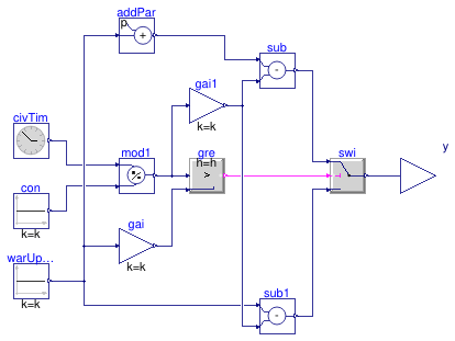
Information
It calculates the total number of hours to next warmup period.
Parameters
| Type | Name | Default | Description |
|---|
| Integer | warUpStaHou | 4 | Warmup period beginning hour |
Connectors
| Type | Name | Description |
|---|
| output RealOutput | y | Hours to next warmup period |
Modelica definition
block HoursToNextWarmup
parameter Integer warUpStaHou=4
;
Buildings.Controls.OBC.CDL.Interfaces.RealOutput y
;
Buildings.Controls.OBC.CDL.Reals.Sources.CivilTime civTim;
Buildings.Controls.OBC.CDL.Reals.Modulo mod1;
Buildings.Controls.OBC.CDL.Reals.Sources.Constant con(
final k=24*3600)
;
Buildings.Controls.OBC.CDL.Reals.Sources.Constant warUpBeg(
final k=warUpStaHou)
;
Buildings.Controls.OBC.CDL.Reals.Greater gre
;
Buildings.Controls.OBC.CDL.Reals.Switch swi;
Buildings.Controls.OBC.CDL.Reals.MultiplyByParameter gai(
final k=3600)
;
Buildings.Controls.OBC.CDL.Reals.AddParameter addPar(
final p=24)
;
Buildings.Controls.OBC.CDL.Reals.MultiplyByParameter gai1(
final k=1/3600)
;
Buildings.Controls.OBC.CDL.Reals.Subtract sub
;
Buildings.Controls.OBC.CDL.Reals.Subtract sub1
;
equation
connect(civTim.y, mod1.u1);
connect(con.y, mod1.u2);
connect(mod1.y, gre.u1);
connect(gre.y, swi.u2);
connect(warUpBeg.y, gai.u);
connect(gai.y, gre.u2);
connect(warUpBeg.y, addPar.u);
connect(mod1.y, gai1.u);
connect(gai1.y, sub.u2);
connect(addPar.y, sub.u1);
connect(warUpBeg.y, sub1.u1);
connect(gai1.y, sub1.u2);
connect(sub.y, swi.u1);
connect(sub1.y, swi.u3);
connect(swi.y, y);
end HoursToNextWarmup;
Block that holds the value of an integer array for a given time

Information
This blocks updates the value of the output array to
match the value of the input array only if the time
since the last update exceeds holdDuration.
Otherwise, the value of the output array is kept equal
to its value at the time of the last update.
At initial time, the value of the output array is set
to the value of the input array, and this is considered
as the first update time.
Parameters
| Type | Name | Default | Description |
|---|
| Real | holdDuration | 1 | Hold duration [s] |
Connectors
| Type | Name | Description |
|---|
| input IntegerInput | u[nin] | Connector of Real input signal |
| output IntegerOutput | y[nout] | Connector of Integer output signal |
Modelica definition
block IntegerArrayHold
parameter Integer nin=0
;
final parameter Integer nout=nin
;
parameter Real holdDuration(
final quantity="Time",
final unit="s")=1
;
Buildings.Controls.OBC.CDL.Interfaces.IntegerInput u[nin]
;
Buildings.Controls.OBC.CDL.Interfaces.IntegerOutput y[nout]
;
protected
Real time_change;
initial algorithm
y := u;
time_change := time;
algorithm
when Modelica.Math.BooleanVectors.anyTrue({
u[i] <>
pre(y[i])
for i
in 1:nin})
and time - time_change > holdDuration
then
y := u;
time_change := time;
end when;
end IntegerArrayHold;
Block that determines the condenser loop mode
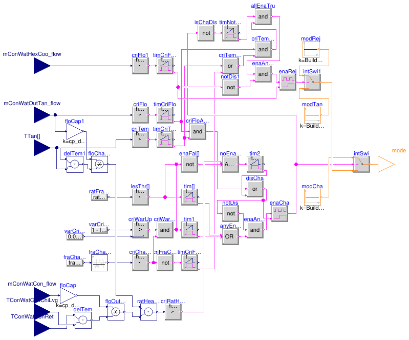
Information
Tank charge fraction and rate of change
The tank charge fraction fraChaTan (-) is computed as the
5-minute moving average of the following expression:
(∑i (TTani - min(TTanSet)) /
(max(TTanSet) - min(TTanSet)) / nTTan - fraUslTan) /
(1 - fraUslTan), where
TTani is the measurement from the i-th temperature sensor
along the vertical axis of the tank,
TTanSet are the tank temperature setpoints (two values for each
tank cycle),
nTTan is the number of temperature sensors along the vertical axis of the tank,
fraUslTan is the useless fraction of the tank which is computed as follows:
fraUslTan = ((max(TTanSet[2]) - min(TTanSet)) / (max(TTanSet) - min(TTanSet)) * hThe + hHee) / hTan,
where hThe is the height of the thermocline (1 m by default)
which is considered useless only during the second tank cycle,
hHee is the upper and lower heel heights above and below the diffusers
(1 m by default), hTan is the tank height (used as an
approximation for the normal operating level of the tank at minimum
temperature). Please see the detailed calculation of the tank charge fraction in
Buildings.DHC.Plants.Combined.Controls.BaseClasses.TankChargeFraction.
The rate of change of the tank charge fraction ratFraChaTan (h-1) is computed
over several time periods (10, 30, 120, 240
and 360 min) as:
ratFraChaTan(Δt) = (fraChaTan(t) - fraChaTan(t - Δt)) / Δt * 3600,
where Δt is the time period in seconds. Please see the detailed calculation
of the rate of change in
Buildings.DHC.Plants.Combined.Controls.BaseClasses.TankChargeFractionRate.
Operating modes
Three operating modes are defined within
Buildings.DHC.Plants.Combined.Controls.ModeCondenserLoop.
Charge Assist
The mode is enabled whenever any of the following conditions
is true for 5 min.
Any of the rates of change exceeds the values specified with the parameter
ratFraChaTanLim.
The tank charge fraction is lower than 97 % and
1 - fraChaTan > 0.08 * abs(nHouToWarUp - 2), where
fraChaTan is the tank charge fraction and
nHouToWarUp is the number
of hours between the present time and the start time of morning warmup (4 AM by default).
The 2-hour offset forces Charge Assist mode two hours before morning warmup
if the tank is not fully charged.
Please see
Buildings.DHC.Plants.Combined.Controls.BaseClasses.HoursToNextWarmup
for the calculation of the number of hours to next warmup period.
The mode is disabled whenever none of the Enable conditions is true for
15 min,
or the flow rate out of the lower port of the tank is positive for 5 min
and the temperature at the bottom of the tank is higher than the maximum tank
temperature setpoint minus 2 K for 5 min.
Heat Rejection
The mode is enabled whenever all of the following conditions are true.
The Charge Assist mode is disabled for 5 min.
The flow rate out of the lower port of the tank is positive for 5 min.
The tank charge fraction is higher than 97 % for 5 min
or the temperature at the bottom of the tank is higher than the maximum tank
temperature setpoint minus 2 K for 5 min.
The mode is disabled whenever there is reverse flow through the cooling
heat exchanger for 1 min.
Tank Charge/Discharge
The mode is enabled whenever neither Charge Assist nor Heat Rejection mode is enabled.
Parameters
| Type | Name | Default | Description |
|---|
| Real | mConWatHexCoo_flow_nominal | | Design total CW mass flow rate through condenser barrels (all units) [kg/s] |
| Real | QHeaPum_flow_nominal | | Design heat flow from heat pumps (all units) [W] |
| Real | ratFraChaTanLim[5] | {-0.3,-0.2,-0.15,-0.10,-0.08} | Rate of change of tank charge fraction (over 10, 30, 120, 240, and 360') that triggers Charge Assist (<0) [1/h] |
| Real | cp_default | Buildings.Utilities.Psychrom... | Specific heat capacity of the fluid [J/(kg.K)] |
| CW loop, TES tank and heat pumps |
| Real | TTanSet[2, 2] | | Tank temperature setpoints: 2 cycles with 2 setpoints [K] |
| Real | fraUslTan | | Useless fraction of TES [1] |
Connectors
| Type | Name | Description |
|---|
| input RealInput | mConWatHexCoo_flow | CW mass flow rate through secondary (plant) side of HX [kg/s] |
| input RealInput | mConWatCon_flow | CW condenser loop mass flow rate [kg/s] |
| input RealInput | TConWatConChiLvg | Chiller and HRC leaving CW temperature [K] |
| input RealInput | TConWatConRet | CWC return temperature [K] |
| input RealInput | mConWatOutTan_flow | Mass flow rate out of lower port of TES tank (>0 when charging) [kg/s] |
| input RealInput | TTan[nTTan] | TES tank temperature [K] |
| output IntegerOutput | mode | Condenser loop operating mode |
Modelica definition
block ModeCondenserLoop
parameter Real mConWatHexCoo_flow_nominal(
final quantity="MassFlowRate",
final unit="kg/s")
;
parameter Real QHeaPum_flow_nominal(
final quantity="HeatFlowRate",
final unit="W")
;
parameter Real TTanSet[2, 2](
each final quantity="ThermodynamicTemperature",
each final unit="K",
each displayUnit="degC")
;
parameter Real fraUslTan(unit="1")
;
parameter Integer nTTan=2
;
parameter Real ratFraChaTanLim[5](
each final unit="1/h")={-0.3, -0.2, -0.15, -0.10, -0.08}
;
parameter Real cp_default(
final quantity="SpecificHeatCapacity",
final unit="J/(kg.K)")=Buildings.Utilities.Psychrometrics.Constants.cpWatLiq
;
Buildings.Controls.OBC.CDL.Interfaces.RealInput mConWatHexCoo_flow(
final unit="kg/s")
;
Buildings.Controls.OBC.CDL.Interfaces.RealInput mConWatCon_flow(
final unit="kg/s")
;
Buildings.Controls.OBC.CDL.Interfaces.RealInput TConWatConChiLvg(
final unit="K",
displayUnit="degC")
;
Buildings.Controls.OBC.CDL.Interfaces.RealInput TConWatConRet(
final unit="K",
displayUnit="degC")
;
Buildings.Controls.OBC.CDL.Interfaces.RealInput mConWatOutTan_flow(
final unit="kg/s")
;
Buildings.Controls.OBC.CDL.Interfaces.RealInput TTan[nTTan](
final unit=
fill("K",nTTan),
displayUnit=
fill("degC", nTTan))
;
Buildings.Controls.OBC.CDL.Interfaces.IntegerOutput mode(
final min=Buildings.DHC.Plants.Combined.Controls.ModeCondenserLoop.tankCharge,
final max=Buildings.DHC.Plants.Combined.Controls.ModeCondenserLoop.heatRejection)
;
Buildings.Controls.OBC.CDL.Reals.LessThreshold lesThr[5](
final t=ratFraChaTanLim,
each h=1E-4)
;
Buildings.Controls.OBC.CDL.Logical.Timer tim[5](
each t=5*60)
;
Buildings.Controls.OBC.CDL.Logical.MultiOr anyEnaTru(
nin=6)
;
Buildings.Controls.OBC.CDL.Reals.Greater criWarUp(
h=1e-3)
;
Buildings.Controls.OBC.CDL.Logical.And criWarUpAndChaLow
;
Buildings.Controls.OBC.CDL.Reals.LessThreshold criChaLow(
t=0.97,
h=1e-3)
;
Buildings.Controls.OBC.CDL.Logical.Not enaFal[6]
;
Buildings.Controls.OBC.CDL.Logical.MultiAnd noEnaTruAndRatCon(
nin=7)
;
Buildings.Controls.OBC.CDL.Logical.Timer tim2(
t=15*60)
;
Buildings.Controls.OBC.CDL.Reals.GreaterThreshold criFlo(
t=1E-3*mConWatHexCoo_flow_nominal,
h=1E-3*mConWatHexCoo_flow_nominal/2)
;
Buildings.Controls.OBC.CDL.Reals.GreaterThreshold criTem(
t=
max(TTanSet)- 2,
h=1e-3)
;
Buildings.Controls.OBC.CDL.Logical.And criFloAndTem
;
Buildings.Controls.OBC.CDL.Logical.Timer timCriFlo(
t=5*60)
;
Buildings.Controls.OBC.CDL.Logical.Or disCha
;
Buildings.Controls.OBC.CDL.Logical.Latch enaCha
;
Buildings.Controls.OBC.CDL.Logical.Timer timNotCha(t=5*60);
Buildings.Controls.OBC.CDL.Logical.Timer timCriTem(t=5*60)
;
Buildings.Controls.OBC.CDL.Logical.Not criFraChaHig
;
Buildings.Controls.OBC.CDL.Logical.And allEnaTru
;
Buildings.Controls.OBC.CDL.Logical.And criTemOrCriChaHigAndTimCriFlo
;
Buildings.Controls.OBC.CDL.Logical.Timer timCriFraChaHig(
t=5*60);
Buildings.Controls.OBC.CDL.Logical.Or criTemOrCriChaHig
;
Buildings.Controls.OBC.CDL.Reals.LessThreshold criFlo1(
t=-1E-3*mConWatHexCoo_flow_nominal,
h=1E-3*mConWatHexCoo_flow_nominal/2);
Buildings.Controls.OBC.CDL.Logical.Timer timCriFlo1(t=60)
;
Buildings.Controls.OBC.CDL.Logical.Latch enaRej
;
Buildings.Controls.OBC.CDL.Integers.Sources.Constant modTan(
final k=Buildings.DHC.Plants.Combined.Controls.ModeCondenserLoop.tankCharge)
;
Buildings.Controls.OBC.CDL.Integers.Sources.Constant modRej(
final k=Buildings.DHC.Plants.Combined.Controls.ModeCondenserLoop.heatRejection)
;
Buildings.Controls.OBC.CDL.Integers.Sources.Constant modCha(
final k=Buildings.DHC.Plants.Combined.Controls.ModeCondenserLoop.chargeAssist)
;
Buildings.Controls.OBC.CDL.Integers.Switch intSwi;
Buildings.Controls.OBC.CDL.Integers.Switch intSwi1;
Buildings.Controls.OBC.CDL.Logical.Not isChaDis
;
Buildings.Controls.OBC.CDL.Logical.And enaAndNotDis
;
Buildings.Controls.OBC.CDL.Logical.Not notDis ;
Buildings.Controls.OBC.CDL.Logical.And enaAndNotDis1
;
Buildings.Controls.OBC.CDL.Logical.Not notDis1
;
Buildings.Controls.OBC.CDL.Logical.Timer tim1(
t=5*60)
;
Buildings.Controls.OBC.CDL.Reals.Subtract delTem
;
Buildings.Controls.OBC.CDL.Reals.Multiply floOutHeaPum
;
Buildings.Controls.OBC.CDL.Reals.MultiplyByParameter floCap(
final k=cp_default)
;
Buildings.Controls.OBC.CDL.Reals.Subtract delTem1
;
Buildings.Controls.OBC.CDL.Reals.MultiplyByParameter floCap1(
final k=cp_default)
;
Buildings.Controls.OBC.CDL.Reals.Multiply floChaTan
;
Buildings.Controls.OBC.CDL.Reals.Subtract ratHeaRec
;
Buildings.Controls.OBC.CDL.Reals.GreaterThreshold criRatHeaRec(
final t=1E-4*(mConWatHexCoo_flow_nominal*(TTanSet[1, 2] - TTanSet[1, 1])*4184 - QHeaPum_flow_nominal),
final h=1E-4*(mConWatHexCoo_flow_nominal*(TTanSet[1, 2] - TTanSet[1, 1])*4184 - QHeaPum_flow_nominal)/2)
;
Buildings.DHC.Plants.Combined.Controls.BaseClasses.TankChargeFraction tanChaFra(
final TTanSet=TTanSet,
final fraUslTan=fraUslTan,
nTTan=nTTan)
;
Buildings.DHC.Plants.Combined.Controls.BaseClasses.TankChargeFractionRate tanChaFraRat
;
Buildings.Controls.OBC.CDL.Reals.Sources.Constant one(
final k=1)
;
Buildings.Controls.OBC.CDL.Reals.Subtract sub3
;
Buildings.DHC.Plants.Combined.Controls.BaseClasses.HoursToNextWarmup nexWarHou
;
Buildings.Controls.OBC.CDL.Reals.Subtract sub
;
Buildings.Controls.OBC.CDL.Reals.Sources.Constant con(
final k=2) ;
Buildings.Controls.OBC.CDL.Reals.Abs abs1
;
Buildings.Controls.OBC.CDL.Reals.MultiplyByParameter gai(
final k=0.08)
;
equation
connect(criWarUp.y, criWarUpAndChaLow.u1);
connect(criChaLow.y, criWarUpAndChaLow.u2);
connect(noEnaTruAndRatCon.y, tim2.u);
connect(disCha.y, enaCha.clr);
connect(criTem.y, timCriTem.u);
connect(criFlo.y, timCriFlo.u);
connect(timCriFlo.passed, criFloAndTem.u1);
connect(timCriTem.passed, criFloAndTem.u2);
connect(criChaLow.y, criFraChaHig.u);
connect(criFloAndTem.y, disCha.u1);
connect(timNotCha.passed, allEnaTru.u1);
connect(criFraChaHig.y, timCriFraChaHig.u);
connect(timCriTem.passed, criTemOrCriChaHig.u1);
connect(timCriFraChaHig.passed, criTemOrCriChaHig.u2);
connect(criFlo1.y, timCriFlo1.u);
connect(timCriFlo1.passed,enaRej. clr);
connect(enaRej.y, intSwi1.u2);
connect(modRej.y, intSwi1.u1);
connect(modTan.y, intSwi1.u3);
connect(intSwi.y, mode);
connect(enaCha.y, intSwi.u2);
connect(modCha.y, intSwi.u1);
connect(intSwi1.y, intSwi.u3);
connect(TTan[nTTan], criTem.u);
connect(isChaDis.y, timNotCha.u);
connect(enaCha.y, isChaDis.u);
connect(mConWatHexCoo_flow, criFlo1.u);
connect(mConWatOutTan_flow, criFlo.u);
connect(disCha.y, notDis.u);
connect(notDis.y, enaAndNotDis.u1);
connect(enaAndNotDis.y, enaCha.u);
connect(enaAndNotDis1.y, enaRej.u);
connect(allEnaTru.y, enaAndNotDis1.u1);
connect(notDis1.y, enaAndNotDis1.u2);
connect(timCriFlo1.passed, notDis1.u);
connect(lesThr.y, tim.u);
connect(criWarUpAndChaLow.y, tim1.u);
connect(enaAndNotDis.u2, anyEnaTru.y);
connect(tim.passed, anyEnaTru.u[1:5]);
connect(tim1.passed, anyEnaTru.u[6]);
connect(lesThr.y, enaFal[1:5].u);
connect(criWarUpAndChaLow.y, enaFal[6].u);
connect(enaFal.y, noEnaTruAndRatCon.u[1:6]);
connect(TConWatConRet, delTem.u1);
connect(TConWatConChiLvg, delTem.u2);
connect(mConWatCon_flow, floCap.u);
connect(floCap.y, floOutHeaPum.u1);
connect(delTem.y, floOutHeaPum.u2);
connect(mConWatOutTan_flow, floCap1.u);
connect(floCap1.y,floChaTan. u1);
connect(delTem1.y,floChaTan. u2);
connect(TTan[1], delTem1.u1);
connect(TTan[nTTan], delTem1.u2);
connect(floOutHeaPum.y, ratHeaRec.u2);
connect(floChaTan.y, ratHeaRec.u1);
connect(criRatHeaRec.y, noEnaTruAndRatCon.u[7]);
connect(tim2.passed, disCha.u2);
connect(ratHeaRec.y, criRatHeaRec.u);
connect(criTemOrCriChaHig.y, criTemOrCriChaHigAndTimCriFlo.u2);
connect(timCriFlo.passed, criTemOrCriChaHigAndTimCriFlo.u1);
connect(criTemOrCriChaHigAndTimCriFlo.y, allEnaTru.u2);
connect(tanChaFra.y, criChaLow.u);
connect(one.y, sub3.u1);
connect(tanChaFra.y, sub3.u2);
connect(sub3.y, criWarUp.u1);
connect(tanChaFra.y, tanChaFraRat.uChaFra);
connect(tanChaFraRat.y, lesThr.u);
connect(TTan, tanChaFra.TTan);
connect(con.y, sub.u2);
connect(nexWarHou.y, sub.u1);
connect(sub.y, abs1.u);
connect(abs1.y, gai.u);
connect(gai.y, criWarUp.u2);
end ModeCondenserLoop;
Block that computes the cascading cooling and direct HR switchover signals
Information
This block computes the command signals to the HRCs to initiate
the switchover into either cascading cooling mode (with the evaporator
indexed to the CHW loop and the condenser indexed to the CW loop)
or direct heat recovery mode (with the evaporator
indexed to the CHW loop and the condenser indexed to the HW loop).
Switching a HRC to cascading cooling mode is done starting from the unit nearest
to the CW interconnection, that is the unit with the highest index.
Switching a HRC to direct heat recovery mode is done starting from the unit nearest
to the CW interconnection and that is not operating in cascading cooling,
that is the unit with the highest index below the lowest index of HRCs operating
in cascading cooling mode.
Parameters
| Type | Name | Default | Description |
|---|
| Integer | nChiHea | | Number of HRC |
Connectors
| Type | Name | Description |
|---|
| input IntegerInput | nCasCoo | Number of units required to be operating in cascading cooling mode |
| input IntegerInput | nHeaCoo | Number of HRC required to be operating in direct HR mode |
| output BooleanOutput | y1Coo[nChiHea] | Command signal for cascading cooling mode |
| output BooleanOutput | y1HeaCoo[nChiHea] | Command signal for direct HR mode |
Modelica definition
Interface class for plant controller
Information
This block serves as an interface class for the plant controller.
Parameters
| Type | Name | Default | Description |
|---|
| Real | PLRStaTra | 0.85 | Part load ratio triggering stage transition [1] |
| Real | cp_default | Buildings.Utilities.Psychrom... | Specific heat capacity of the fluid [J/(kg.K)] |
| CHW loop and cooling-only chillers |
| Integer | nChi | | Number of units operating at design conditions |
| Integer | nPumChiWat | | Number of CHW pumps operating at design conditions |
| Real | TChiWatSup_nominal | | Design (minimum) CHW supply temperature [K] |
| Real | QChiWatChi_flow_nominal | | Cooling design heat flow rate of cooling-only chillers (all units) [W] |
| Real | mChiWat_flow_nominal | | CHW design mass flow rate (all units) [kg/s] |
| Real | dpChiWatSet_max | | Design (maximum) CHW differential pressure setpoint [Pa] |
| Real | mChiWatChi_flow_nominal | | Chiller CHW design mass flow rate (each unit) [kg/s] |
| Real | mChiWatChi_flow_min | | Chiller CHW minimum mass flow rate (each unit) [kg/s] |
| Real | mConWatChi_flow_nominal | | Chiller CW design mass flow rate (each unit) [kg/s] |
| Real | dpEvaChi_nominal | | Chiller evaporator design pressure drop (each unit) [Pa] |
| Real | dpValEvaChi_nominal | | Chiller evaporator isolation valve design pressure drop (each unit) [Pa] |
| Real | dTLifChi_min | | Minimum chiller lift at minimum load [K] |
| Real | dTLifChi_nominal | | Design chiller lift [K] |
| HW loop and heat recovery chillers |
| Integer | nChiHea | | Number of units operating at design conditions |
| Integer | nPumHeaWat | | Number of HW pumps operating at design conditions |
| Real | THeaWatSup_nominal | | Design (maximum) HW supply temperature [K] |
| Real | QChiWatCasCoo_flow_nominal | | Cooling design heat flow rate of HRC in cascading cooling mode (all units) [W] |
| Real | QChiWatCasCoo_flow_nominal_approx | | Cooling design heat flow rate of HRC in cascading cooling mode (all units), approximate for scaling [W] |
| Real | QHeaWat_flow_nominal | | Heating design heat flow rate (all units) [W] |
| Real | mHeaWat_flow_nominal | | HW design mass flow rate (all units) [kg/s] |
| Real | dpHeaWatSet_max | | Design (maximum) HW differential pressure setpoint [Pa] |
| Real | mChiWatChiHea_flow_nominal | | HRC CHW design mass flow rate (each unit) [kg/s] |
| Real | mChiWatChiHea_flow_min | | HRC CHW minimum mass flow rate (each unit) [kg/s] |
| Real | mConWatChiHea_flow_nominal | | HRC CW design mass flow rate (each unit) [kg/s] |
| Real | mHeaWatChiHea_flow_min | | Chiller HW minimum mass flow rate (each unit) [kg/s] |
| Real | dpEvaChiHea_nominal | | Design chiller evaporator pressure drop (each unit) [Pa] |
| Real | dpValEvaChiHea_nominal | | HRC evaporator isolation valve design pressure drop (each unit) [Pa] |
| CW loop, TES tank and heat pumps |
| Integer | nHeaPum | | Number of heat pumps operating at design conditions |
| Integer | nPumConWatCon | | Number of CW pumps serving condenser barrels at design conditions |
| Integer | nPumConWatEva | | Number of CW pumps serving evaporator barrels at design conditions |
| Real | QHeaPum_flow_nominal | | Heating design heat flow rate of heat pumps (all units) [W] |
| Real | mConWatCon_flow_nominal | | Design total CW mass flow rate through condenser barrels (all units) [kg/s] |
| Real | mConWatEva_flow_nominal | | Design total CW mass flow rate through evaporator barrels (all units) [kg/s] |
| Real | dpConWatConSet_max | | Design (maximum) CW condenser loop differential pressure setpoint [Pa] |
| Real | dpConWatEvaSet_max | | Design (maximum) CW evaporator loop differential pressure setpoint [Pa] |
| Real | TTanSet[2, 2] | | Tank temperature setpoints: 2 cycles with 2 setpoints [K] |
| Real | fraUslTan | | Useless fraction of TES [1] |
| Real | ratFraChaTanLim[5] | {-0.3,-0.2,-0.15,-0.10,-0.08} | Rate of change of tank charge fraction (over 10, 30, 120, 240, and 360') that triggers Charge Assist (<0) [1/h] |
| Cooling tower loop |
| Integer | nCoo | | Number of cooling tower cells operating at design conditions |
| Integer | nPumConWatCoo | | Number of CW pumps serving cooling towers at design conditions |
| Real | dTHexCoo_nominal | | Design heat exchanger approach [K] |
| Dynamics |
| Motor speed |
| Real | riseTime | 30 | Time needed to change motor speed between zero and full speed [s] |
| Time needed to open or close valve |
| Real | strokeTime | 120 | Valve stroke time [s] |
Connectors
| Type | Name | Description |
|---|
| input BooleanInput | u1Coo | Cooling enable signal |
| input BooleanInput | u1Hea | Heating enable signal |
| input RealInput | TChiWatSupSet | CHW supply temperature setpoint [K] |
| input RealInput | THeaWatSupSet | HW supply temperature setpoint [K] |
| output RealOutput | yValEvaChi[nChi] | Cooling-only chiller evaporator isolation valve commanded position |
| output RealOutput | yValConChi[nChi] | Cooling-only chiller condenser isolation valve commanded position [1] |
| output BooleanOutput | y1Chi[nChi] | Cooling-only chiller On/Off command |
| output BooleanOutput | y1PumChiWat[nPumChiWat] | CHW pump Start command |
| output RealOutput | yPumChiWat | CHW pump speed signal [1] |
| output RealOutput | yValEvaChiHea[nChiHea] | HRC evaporator isolation valve commanded position [1] |
| output BooleanOutput | y1ChiHea[nChiHea] | HRC On/Off command |
| output BooleanOutput | y1CooChiHea[nChiHea] | HRC cooling mode switchover command: true for cooling, false for heating |
| output RealOutput | yValConChiHea[nChiHea] | HRC condenser isolation valve commanded position [1] |
| output BooleanOutput | y1PumHeaWat[nPumHeaWat] | HW pump Start command |
| output RealOutput | yPumHeaWat | HW pump speed signal [1] |
| output RealOutput | yValChiWatMinByp | CHW minimum flow bypass valve control signal [1] |
| output RealOutput | yValHeaWatMinByp | HW minimum flow bypass valve control signal [1] |
| output BooleanOutput | y1PumConWatCon[nPumConWatCon] | CW pump serving condenser barrels Start command |
| output RealOutput | yPumConWatCon | CW pump serving condenser barrels Speed command [1] |
| output BooleanOutput | y1PumConWatEva[nPumConWatEva] | CW pump serving evaporator barrels Start command |
| output RealOutput | yPumConWatEva | CW pump serving evaporator barrels Speed command [1] |
| output BooleanOutput | y1HeaPum[nHeaPum] | Heat pump On/Off command |
| output RealOutput | THeaPumSet | Heat pump supply temperature setpoint [K] |
| output RealOutput | yValBypTan | TES tank bypass valve commanded position [1] |
| output BooleanOutput | y1Coo[nCoo] | Cooling tower Start command |
| output RealOutput | yCoo | Cooling tower fan speed command [1] |
| output BooleanOutput | y1PumConWatCoo[nPumConWatCoo] | Cooling tower pump Start command |
| output RealOutput | TChiHeaSet[nChiHea] | HRC supply temperature setpoint [K] |
| output BooleanOutput | y1HeaCooChiHea[nChiHea] | HRC direct heat recovery switchover command: true for direct HR, false for cascading |
| input RealInput | dpChiWatSet | CHW differential pressure setpoint (for local dp sensor) [Pa] |
| input RealInput | dpHeaWatSet | HW differential pressure setpoint (for local dp sensor) [Pa] |
| input RealInput | dpChiWat | CHW differential pressure (from local dp sensor) [Pa] |
| input RealInput | dpHeaWat | HW differential pressure (from local dp sensor) [Pa] |
| input RealInput | mChiWatPri_flow | Primary CHW mass flow rate [kg/s] |
| input RealInput | mHeaWatPri_flow | Primary HW mass flow rate [kg/s] |
| input RealInput | dpConWatCon | CW condenser loop differential pressure [Pa] |
| input RealInput | dpConWatEva | CW evaporator loop differential pressure [Pa] |
| input RealInput | mConWatCon_flow | CW condenser loop mass flow rate [kg/s] |
| input RealInput | mConWatEva_flow | CW evaporator loop mass flow rate [kg/s] |
| input RealInput | TChiWatSup | CHW supply temperature [K] |
| input RealInput | TChiWatPriRet | Primary CHW return temperature [K] |
| input RealInput | THeaWatPriRet | Primary HW return temperature [K] |
| input RealInput | TTan[nTTan] | TES tank temperature [K] |
| input RealInput | mConWatHexCoo_flow | CW mass flow rate through secondary (plant) side of HX [kg/s] |
| input RealInput | mConWatOutTan_flow | Mass flow rate out of lower port of TES tank (>0 when charging) [kg/s] |
| input RealInput | mEvaChi_flow[nChi] | Chiller evaporator barrel mass flow rate [kg/s] |
| input RealInput | mConChi_flow[nChi] | Chiller condenser barrel mass flow rate [kg/s] |
| input RealInput | mEvaChiHea_flow[nChiHea] | HRC evaporator barrel mass flow rate [kg/s] |
| input RealInput | mConChiHea_flow[nChiHea] | HRC condenser barrel mass flow rate [kg/s] |
| output RealOutput | yValEvaSwiHea[nChiHea] | HRC evaporator switchover valve commanded position [1] |
| output RealOutput | yValConSwiChiHea[nChiHea] | HRC condenser switchover valve commanded position [1] |
| input RealInput | TEvaLvgChiHea[nChiHea] | HRC evaporator barrel leaving temperature [K] |
| input RealInput | THeaWatSup | HW supply temperature [K] |
| output RealOutput | yPumConWatCoo | Cooling tower pump speed command |
| input RealInput | TConWatConChiEnt | Chiller and HRC entering CW temperature [K] |
| input RealInput | TConWatConChiLvg | Chiller and HRC leaving CW temperature [K] |
| input RealInput | TConWatCooSup | Cooling tower loop CW supply temperature [K] |
| input RealInput | TConWatCooRet | Cooling tower loop CW return temperature [K] |
| input RealInput | TConWatHexCooEnt | HX entering CW temperature [K] |
| input RealInput | TConWatHexCooLvg | HX leaving CW temperature [K] |
| input RealInput | TConEntChiHea[nChiHea] | HRC condenser barrel entering temperature [K] |
| input RealInput | TConLvgChiHea[nChiHea] | HRC condenser barrel leaving temperature [K] |
| input RealInput | TConWatEvaEnt | HRC evaporator entering CW temperature [K] |
| output RealOutput | yValConWatEvaMix | HRC evaporator CW mixing valve commanded position |
| input RealInput | TConWatConRet | Condenser loop CW return temperature [K] |
| input RealInput | TConLvgChi[nChi] | Chiller condenser barrel leaving temperature [K] |
| output RealOutput | yValConWatByp | CW chiller bypass valve control signal [1] |
Modelica definition
block PartialController
parameter Integer nChi(
final min=1, start=1)
;
parameter Integer nPumChiWat(
final min=1, start=1)
;
parameter Real TChiWatSup_nominal(
final unit="K",
displayUnit="degC",
final quantity="ThermodynamicTemperature")
;
parameter Integer nChiHea(
final min=1, start=1)
;
parameter Integer nPumHeaWat(
final min=1, start=1)
;
parameter Real THeaWatSup_nominal(
final unit="K",
displayUnit="degC",
final quantity="ThermodynamicTemperature")
;
parameter Integer nHeaPum(
final min=1, start=1)
;
parameter Integer nPumConWatCon(
final min=1, start=1)
;
parameter Integer nPumConWatEva(
final min=1, start=1)
;
parameter Integer nCoo(
final min=1, start=1)
;
parameter Integer nPumConWatCoo(
final min=1, start=1)
;
parameter Real QChiWatChi_flow_nominal(
final unit="W",
final quantity="HeatFlowRate")
;
parameter Real QHeaPum_flow_nominal(
final unit="W",
final quantity="HeatFlowRate")
;
parameter Real PLRStaTra(
final unit="1",
final min=0,
final max=1) = 0.85
;
parameter Real QChiWatCasCoo_flow_nominal(
final unit="W",
final quantity="HeatFlowRate")
;
parameter Real QChiWatCasCoo_flow_nominal_approx(
final unit="W",
final quantity="HeatFlowRate")
;
final parameter Real QChiWat_flow_nominal(
final unit="W",
final quantity="HeatFlowRate")=
QChiWatChi_flow_nominal+QChiWatCasCoo_flow_nominal
;
parameter Real QHeaWat_flow_nominal(
final unit="W",
final quantity="HeatFlowRate")
;
parameter Real cp_default(
final unit="J/(kg.K)",
final quantity="SpecificHeatCapacity")=
Buildings.Utilities.Psychrometrics.Constants.cpWatLiq
;
parameter Real mChiWat_flow_nominal(
final min=0,
final unit="kg/s",
final quantity="MassFlowRate")
;
parameter Real dpChiWatSet_max(
final quantity="PressureDifference",
final min=0,
final unit="Pa",
displayUnit="Pa")
;
parameter Real mHeaWat_flow_nominal(
final unit="kg/s",
final quantity="MassFlowRate")
;
parameter Real dpHeaWatSet_max(
final quantity="PressureDifference",
final min=0,
final unit="Pa",
displayUnit="Pa")
;
parameter Real mConWatCon_flow_nominal(
final min=0,
final unit="kg/s",
final quantity="MassFlowRate")
;
parameter Real mConWatEva_flow_nominal(
final min=0,
final unit="kg/s",
final quantity="MassFlowRate")
;
parameter Real mChiWatChi_flow_nominal(
final unit="kg/s",
final quantity="MassFlowRate")
;
parameter Real mChiWatChi_flow_min(
final unit="kg/s",
final quantity="MassFlowRate")
;
parameter Real mConWatChi_flow_nominal(
final unit="kg/s",
final quantity="MassFlowRate")
;
parameter Real mChiWatChiHea_flow_nominal(
final unit="kg/s",
final quantity="MassFlowRate")
;
parameter Real mChiWatChiHea_flow_min(
final unit="kg/s",
final quantity="MassFlowRate")
;
parameter Real mConWatChiHea_flow_nominal(
final unit="kg/s",
final quantity="MassFlowRate")
;
parameter Real mHeaWatChiHea_flow_min(
final unit="kg/s",
final quantity="MassFlowRate")
;
parameter Real dpEvaChi_nominal(
final quantity="PressureDifference",
final min=0,
final unit="Pa",
displayUnit="Pa")
;
parameter Real dpValEvaChi_nominal(
final quantity="PressureDifference",
final min=0,
final unit="Pa",
displayUnit="Pa")
;
parameter Real dpEvaChiHea_nominal(
final quantity="PressureDifference",
final min=0,
final unit="Pa",
displayUnit="Pa")
;
parameter Real dpValEvaChiHea_nominal(
final quantity="PressureDifference",
final min=0,
final unit="Pa",
displayUnit="Pa")
;
parameter Real dpConWatConSet_max(
final quantity="PressureDifference",
final min=0,
final unit="Pa",
displayUnit="Pa")
;
parameter Real dpConWatEvaSet_max(
final quantity="PressureDifference",
final min=0,
final unit="Pa",
displayUnit="Pa")
;
parameter Real TTanSet[2, 2](
each final unit="K",
each displayUnit="degC",
each final quantity="ThermodynamicTemperature")
;
parameter Real fraUslTan(
final unit="1",
final min=0,
final max=1)
;
parameter Integer nTTan(
final min=0)=0
;
parameter Real ratFraChaTanLim[5](
each final unit="1/h")=
{-0.3, -0.2, -0.15, -0.10, -0.08}
;
parameter Real dTLifChi_min(
final unit="K",
final quantity="TemperatureDifference")
;
parameter Real dTLifChi_nominal(
final unit="K",
final quantity="TemperatureDifference")
;
parameter Real dTHexCoo_nominal(
final unit="K",
final quantity="TemperatureDifference")
;
parameter Real riseTime(
final quantity="Time",
final unit="s")=30
;
parameter Real strokeTime(
final quantity="Time",
final unit="s")=120
;
Buildings.Controls.OBC.CDL.Interfaces.BooleanInput u1Coo
;
Buildings.Controls.OBC.CDL.Interfaces.BooleanInput u1Hea
;
Buildings.Controls.OBC.CDL.Interfaces.RealInput TChiWatSupSet(
final unit="K",
displayUnit="degC") ;
Buildings.Controls.OBC.CDL.Interfaces.RealInput THeaWatSupSet(
final unit="K",
displayUnit="degC")
;
Buildings.Controls.OBC.CDL.Interfaces.RealOutput yValEvaChi[nChi]
;
Buildings.Controls.OBC.CDL.Interfaces.RealOutput yValConChi[nChi](
each final unit="1")
;
Buildings.Controls.OBC.CDL.Interfaces.BooleanOutput y1Chi[nChi]
;
Buildings.Controls.OBC.CDL.Interfaces.BooleanOutput y1PumChiWat[nPumChiWat]
;
Buildings.Controls.OBC.CDL.Interfaces.RealOutput yPumChiWat(
final unit="1")
;
Buildings.Controls.OBC.CDL.Interfaces.RealOutput yValEvaChiHea[nChiHea](
each final unit="1") ;
Buildings.Controls.OBC.CDL.Interfaces.BooleanOutput y1ChiHea[nChiHea]
;
Buildings.Controls.OBC.CDL.Interfaces.BooleanOutput y1CooChiHea[nChiHea]
;
Buildings.Controls.OBC.CDL.Interfaces.RealOutput yValConChiHea[nChiHea](
each final unit="1") ;
Buildings.Controls.OBC.CDL.Interfaces.BooleanOutput y1PumHeaWat[nPumHeaWat]
;
Buildings.Controls.OBC.CDL.Interfaces.RealOutput yPumHeaWat(
final unit="1")
;
Buildings.Controls.OBC.CDL.Interfaces.RealOutput yValChiWatMinByp(
final unit="1")
;
Buildings.Controls.OBC.CDL.Interfaces.RealOutput yValHeaWatMinByp(
final unit="1") ;
Buildings.Controls.OBC.CDL.Interfaces.BooleanOutput y1PumConWatCon[nPumConWatCon]
;
Buildings.Controls.OBC.CDL.Interfaces.RealOutput yPumConWatCon(
final unit="1")
;
Buildings.Controls.OBC.CDL.Interfaces.BooleanOutput y1PumConWatEva[nPumConWatEva]
;
Buildings.Controls.OBC.CDL.Interfaces.RealOutput yPumConWatEva(
final unit="1")
;
Buildings.Controls.OBC.CDL.Interfaces.BooleanOutput y1HeaPum[nHeaPum]
;
Buildings.Controls.OBC.CDL.Interfaces.RealOutput THeaPumSet(
final unit="K", displayUnit="degC") ;
Buildings.Controls.OBC.CDL.Interfaces.RealOutput yValBypTan(
final unit="1") ;
Buildings.Controls.OBC.CDL.Interfaces.BooleanOutput y1Coo[nCoo]
;
Buildings.Controls.OBC.CDL.Interfaces.RealOutput yCoo(
final unit="1") ;
Buildings.Controls.OBC.CDL.Interfaces.BooleanOutput y1PumConWatCoo[
nPumConWatCoo] ;
Buildings.Controls.OBC.CDL.Interfaces.RealOutput TChiHeaSet[nChiHea](
each final unit="K",
each displayUnit="degC")
;
Buildings.Controls.OBC.CDL.Interfaces.BooleanOutput y1HeaCooChiHea[nChiHea]
;
Buildings.Controls.OBC.CDL.Interfaces.RealInput dpChiWatSet(
final unit="Pa",
final min=0) ;
Buildings.Controls.OBC.CDL.Interfaces.RealInput dpHeaWatSet(
final unit="Pa",
final min=0)
;
Buildings.Controls.OBC.CDL.Interfaces.RealInput dpChiWat(
final unit="Pa")
;
Buildings.Controls.OBC.CDL.Interfaces.RealInput dpHeaWat(
final unit="Pa")
;
Buildings.Controls.OBC.CDL.Interfaces.RealInput mChiWatPri_flow(
final unit=
"kg/s") ;
Buildings.Controls.OBC.CDL.Interfaces.RealInput mHeaWatPri_flow(
final unit=
"kg/s") ;
Buildings.Controls.OBC.CDL.Interfaces.RealInput dpConWatCon(
final unit="Pa")
;
Buildings.Controls.OBC.CDL.Interfaces.RealInput dpConWatEva(
final unit="Pa")
;
Buildings.Controls.OBC.CDL.Interfaces.RealInput mConWatCon_flow(
final unit=
"kg/s") ;
Buildings.Controls.OBC.CDL.Interfaces.RealInput mConWatEva_flow(
final unit=
"kg/s") ;
Buildings.Controls.OBC.CDL.Interfaces.RealInput TChiWatSup(
final unit="K",
displayUnit="degC") ;
Buildings.Controls.OBC.CDL.Interfaces.RealInput TChiWatPriRet(
final unit="K",
displayUnit="degC") ;
Buildings.Controls.OBC.CDL.Interfaces.RealInput THeaWatPriRet(
final unit="K",
displayUnit="degC") ;
Buildings.Controls.OBC.CDL.Interfaces.RealInput TTan[nTTan](
each final unit="K",
each displayUnit="degC")
;
Buildings.Controls.OBC.CDL.Interfaces.RealInput mConWatHexCoo_flow(
final unit
="kg/s") ;
Buildings.Controls.OBC.CDL.Interfaces.RealInput mConWatOutTan_flow(
final unit
="kg/s")
;
Buildings.Controls.OBC.CDL.Interfaces.RealInput mEvaChi_flow[nChi](
each final unit="kg/s")
;
Buildings.Controls.OBC.CDL.Interfaces.RealInput mConChi_flow[nChi](
each final unit="kg/s")
;
Buildings.Controls.OBC.CDL.Interfaces.RealInput mEvaChiHea_flow[nChiHea](
each final unit="kg/s")
;
Buildings.Controls.OBC.CDL.Interfaces.RealInput mConChiHea_flow[nChiHea](
each final unit="kg/s")
;
Buildings.Controls.OBC.CDL.Interfaces.RealOutput yValEvaSwiHea[nChiHea](
each final unit="1")
;
Buildings.Controls.OBC.CDL.Interfaces.RealOutput yValConSwiChiHea[nChiHea](
each final unit="1")
;
Buildings.Controls.OBC.CDL.Interfaces.RealInput TEvaLvgChiHea[nChiHea](
each final unit="K",
each displayUnit="degC")
;
Buildings.Controls.OBC.CDL.Interfaces.RealInput THeaWatSup(
final unit="K",
displayUnit="degC") ;
Buildings.Controls.OBC.CDL.Interfaces.RealOutput yPumConWatCoo
;
Buildings.Controls.OBC.CDL.Interfaces.RealInput TConWatConChiEnt(
final unit=
"K", displayUnit="degC") ;
Buildings.Controls.OBC.CDL.Interfaces.RealInput TConWatConChiLvg(
final unit=
"K", displayUnit="degC") ;
Buildings.Controls.OBC.CDL.Interfaces.RealInput TConWatCooSup(
final unit="K",
displayUnit="degC") ;
Buildings.Controls.OBC.CDL.Interfaces.RealInput TConWatCooRet(
final unit="K",
displayUnit="degC") ;
Buildings.Controls.OBC.CDL.Interfaces.RealInput TConWatHexCooEnt(
final unit="K",
displayUnit="degC") ;
Buildings.Controls.OBC.CDL.Interfaces.RealInput TConWatHexCooLvg(
final unit="K",
displayUnit="degC") ;
Buildings.Controls.OBC.CDL.Interfaces.RealInput TConEntChiHea[nChiHea](
each final
unit="K",
each displayUnit="degC")
;
Buildings.Controls.OBC.CDL.Interfaces.RealInput TConLvgChiHea[nChiHea](
each final
unit="K",
each displayUnit="degC")
;
Buildings.Controls.OBC.CDL.Interfaces.RealInput TConWatEvaEnt(
final unit="K",
displayUnit="degC") ;
Buildings.Controls.OBC.CDL.Interfaces.RealOutput yValConWatEvaMix
;
Buildings.Controls.OBC.CDL.Interfaces.RealInput TConWatConRet(
final unit
="K", displayUnit="degC") ;
Buildings.Controls.OBC.CDL.Interfaces.RealInput TConLvgChi[nChi](
each final
unit="K",
each displayUnit="degC")
;
Buildings.Controls.OBC.CDL.Interfaces.RealOutput yValConWatByp(
final unit="1")
;
end PartialController;
Block that computes the stage index out of staging signals
Information
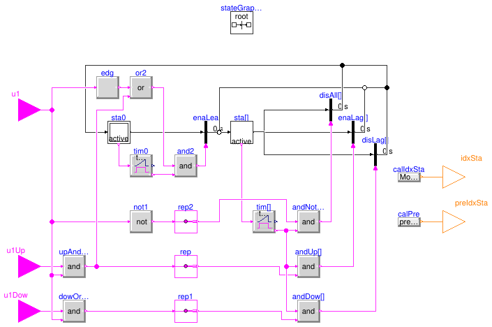
This block is used to compute the stage index of the plant or
of multiple lead/lag units such as pump groups.
At initial time, stage #0 is active.
The transition to stage #1 is triggered when stage #0 has been active
for the minimum runtime and when either the Enable signal u1
has a rising edge or when the stage up signal u1Up is true.
From stage #i, the transition to stage #i+1 (resp. i-1) is triggered
when stage #i has been active for the minimum runtime and when the
stage up signal u1Up (resp. stage down signal u1Dow)
is true.
From stage #i, the transition to stage #0 is triggered
when stage #i has been active for the minimum runtime and the Enable signal
u1 is false.
Parameters
| Type | Name | Default | Description |
|---|
| Integer | nSta | | Number of stages |
| Real | tSta | 0 | Minimum runtime of each stage [s] |
Connectors
Modelica definition
block StageIndex
parameter Integer nSta(start=1)
;
parameter Real tSta(
final quantity="Time",
final unit="s")=0
;
Buildings.Controls.OBC.CDL.Interfaces.BooleanInput u1
;
Buildings.Controls.OBC.CDL.Interfaces.BooleanInput u1Up
;
Buildings.Controls.OBC.CDL.Interfaces.BooleanInput u1Dow
;
Buildings.Controls.OBC.CDL.Interfaces.IntegerOutput idxSta
;
Buildings.Controls.OBC.CDL.Interfaces.IntegerOutput preIdxSta
;
Modelica.StateGraph.InitialStepWithSignal sta0(
final nOut=1,
final nIn=nSta+1)
;
Modelica.StateGraph.StepWithSignal sta[nSta](
each final nIn=2,
each final nOut=3)
;
Modelica.StateGraph.TransitionWithSignal enaLea(
final enableTimer=false) ;
inner Modelica.StateGraph.StateGraphRoot stateGraphRoot
;
Modelica.StateGraph.TransitionWithSignal enaLag[nSta](
each final enableTimer=false)
;
Buildings.Controls.OBC.CDL.Logical.Timer tim[nSta](
each final t=tSta)
;
Buildings.Controls.OBC.CDL.Logical.Timer tim0(
final t=tSta)
;
Buildings.Controls.OBC.CDL.Logical.And and2
;
Buildings.Controls.OBC.CDL.Logical.And andUp[nSta]
;
Buildings.Controls.OBC.CDL.Routing.BooleanScalarReplicator rep(
final nout=nSta)
;
Buildings.Controls.OBC.CDL.Logical.And andDow[nSta]
;
Buildings.Controls.OBC.CDL.Routing.BooleanScalarReplicator rep1(
final nout=nSta) ;
Modelica.StateGraph.TransitionWithSignal disLag[nSta](
each final enableTimer=false)
;
Modelica.StateGraph.TransitionWithSignal disAll[nSta](
each final enableTimer=false)
;
Buildings.Controls.OBC.CDL.Logical.And andNotEna[nSta]
;
Buildings.Controls.OBC.CDL.Routing.BooleanScalarReplicator rep2(
final nout=nSta)
;
Buildings.Controls.OBC.CDL.Logical.Not not1
;
Modelica.Blocks.Sources.IntegerExpression calIdxSta(
final y=
Modelica.Math.BooleanVectors.firstTrueIndex(sta.active))
;
Buildings.Controls.OBC.CDL.Logical.Edge edg
;
Buildings.Controls.OBC.CDL.Logical.Or or2
;
Modelica.Blocks.Sources.IntegerExpression calPre(
final y=
pre(idxSta))
;
Buildings.Controls.OBC.CDL.Logical.And upAndEna
;
Buildings.Controls.OBC.CDL.Logical.And dowOrDis
;
initial equation
preIdxSta=0;
equation
for i
in 1:(nSta - 1)
loop
connect(enaLag[i].outPort, sta[i+1].inPort[1]);
connect(disLag[i+1].outPort, sta[i].inPort[2]);
end for;
connect(enaLag[nSta].outPort, sta[nSta].inPort[2]);
connect(disAll.outPort, sta0.inPort[1:nSta]);
connect(sta0.outPort[1], enaLea.inPort);
connect(enaLea.outPort, sta[1].inPort[1]);
connect(disLag[1].outPort, sta0.inPort[nSta+1]);
connect(sta.outPort[1], disAll.inPort);
connect(sta.outPort[2], enaLag.inPort);
connect(sta.outPort[3], disLag.inPort);
connect(sta.active, tim.u);
connect(sta0.active, tim0.u);
connect(tim0.passed, and2.u2);
connect(and2.y, enaLea.condition);
connect(rep.y, andUp.u2);
connect(andUp.y, enaLag.condition);
connect(tim.passed, andDow.u1);
connect(rep1.y, andDow.u2);
connect(tim.passed, andUp.u1);
connect(andDow.y, disLag.condition);
connect(u1, not1.u);
connect(not1.y, rep2.u);
connect(rep2.y, andNotEna.u1);
connect(tim.passed, andNotEna.u2);
connect(andNotEna.y, disAll.condition);
connect(calIdxSta.y, idxSta);
connect(u1, edg.u);
connect(edg.y, or2.u1);
connect(or2.y, and2.u1);
connect(calPre.y, preIdxSta);
connect(u1, upAndEna.u2);
connect(u1Up, upAndEna.u1);
connect(upAndEna.y, rep.u);
connect(dowOrDis.y, rep1.u);
connect(u1Dow, dowOrDis.u1);
connect(u1, dowOrDis.u2);
connect(upAndEna.y, or2.u2);
end StageIndex;
Total capacity at current stages times stage-up PLR limit
Information
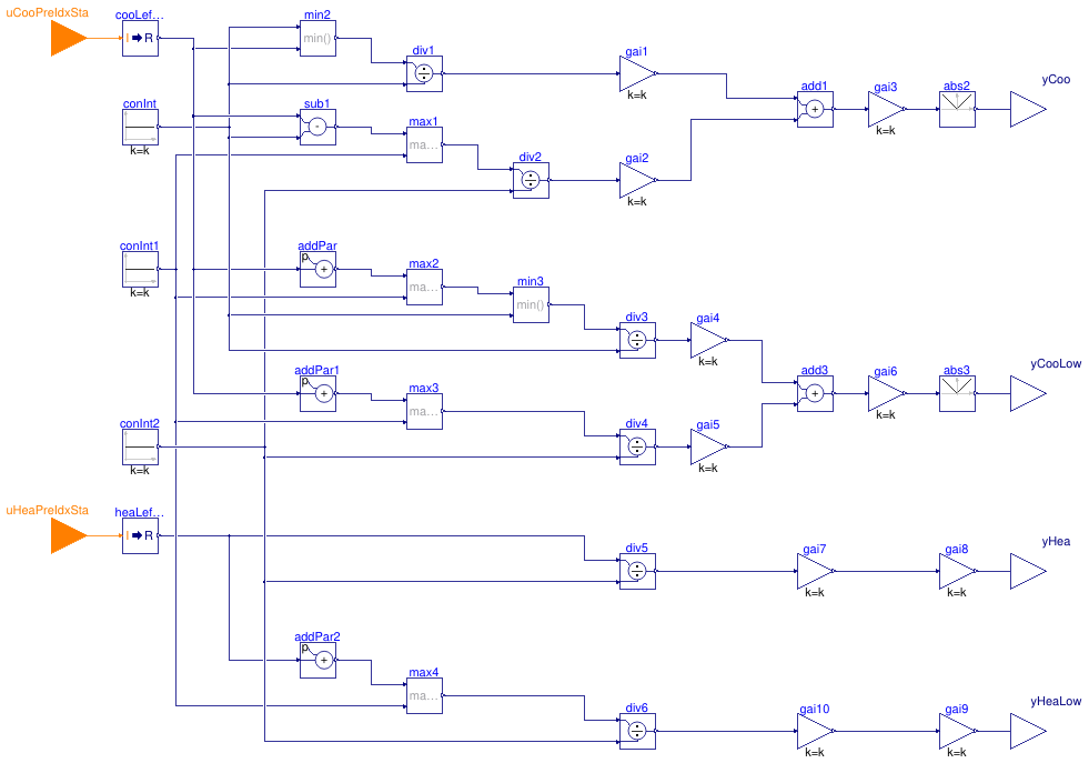
It calcualtes the total capacity at current stages times stage-up PLR limit.
Parameters
| Type | Name | Default | Description |
|---|
| Real | PLRStaTra | 0.85 | Part load ratio triggering stage transition [1] |
| CHW loop and cooling-only chillers |
| Integer | nChi | | Number of units operating at design conditions |
| Real | QChiWatChi_flow_nominal | | Cooling design heat flow rate of cooling-only chillers (all units) [W] |
| HW loop and heat recovery chillers |
| Integer | nChiHea | | Number of units operating at design conditions |
| Real | QChiWatCasCoo_flow_nominal | | Cooling design heat flow rate of HRC in cascading cooling mode (all units) [W] |
| Real | QHeaWat_flow_nominal | | Heating design heat flow rate (all units) [W] |
Connectors
| Type | Name | Description |
|---|
| input IntegerInput | uCooPreIdxSta | Left limit of the cooling stage index |
| input IntegerInput | uHeaPreIdxSta | Left limit of the heating stage index |
| output RealOutput | yCoo | Total capacity at current stage (>0) times stage-up PLR limit |
| output RealOutput | yCooLow | Total capacity at next lower stage (>0) times stage-down PLR limit |
| output RealOutput | yHea | Total capacity at current stage (>0) times stage-up PLR limit |
| output RealOutput | yHeaLow | Total capacity at next lower stage (>0) times stage-down PLR limit |
Modelica definition
block StagingCapacity
parameter Integer nChi(
final min=1, start=1)
;
parameter Real QChiWatChi_flow_nominal(
final unit="W",
final quantity="HeatFlowRate")
;
parameter Integer nChiHea(
final min=1, start=1)
;
parameter Real PLRStaTra(unit="1") = 0.85
;
parameter Real QChiWatCasCoo_flow_nominal(
final unit="W",
final quantity="HeatFlowRate")
;
parameter Real QHeaWat_flow_nominal(
final unit="W",
final quantity="HeatFlowRate")
;
Buildings.Controls.OBC.CDL.Interfaces.IntegerInput uCooPreIdxSta
;
Buildings.Controls.OBC.CDL.Interfaces.IntegerInput uHeaPreIdxSta
;
Buildings.Controls.OBC.CDL.Interfaces.RealOutput yCoo
;
Buildings.Controls.OBC.CDL.Interfaces.RealOutput yCooLow
;
Buildings.Controls.OBC.CDL.Interfaces.RealOutput yHea
;
Buildings.Controls.OBC.CDL.Interfaces.RealOutput yHeaLow
;
Buildings.Controls.OBC.CDL.Reals.Sources.Constant conInt(
final k=nChi)
;
Buildings.Controls.OBC.CDL.Reals.Min min2 ;
Buildings.Controls.OBC.CDL.Conversions.IntegerToReal cooLefLimInd
;
Buildings.Controls.OBC.CDL.Reals.Divide div1
;
Buildings.Controls.OBC.CDL.Reals.MultiplyByParameter gai1(
final k=QChiWatChi_flow_nominal)
;
Buildings.Controls.OBC.CDL.Reals.Subtract sub1
;
Buildings.Controls.OBC.CDL.Reals.Sources.Constant conInt1(
final k=0) ;
Buildings.Controls.OBC.CDL.Reals.Max max1 ;
Buildings.Controls.OBC.CDL.Reals.Divide div2
;
Buildings.Controls.OBC.CDL.Reals.Sources.Constant conInt2(
final k=nChiHea)
;
Buildings.Controls.OBC.CDL.Reals.MultiplyByParameter gai2(
final k=QChiWatCasCoo_flow_nominal)
;
Buildings.Controls.OBC.CDL.Reals.Add add1 ;
Buildings.Controls.OBC.CDL.Reals.MultiplyByParameter gai3(
final k=PLRStaTra)
;
Buildings.Controls.OBC.CDL.Reals.Abs abs2 ;
Buildings.Controls.OBC.CDL.Reals.AddParameter addPar(
final p=-1)
;
Buildings.Controls.OBC.CDL.Reals.Max max2 ;
Buildings.Controls.OBC.CDL.Reals.Min min3 ;
Buildings.Controls.OBC.CDL.Reals.Divide div3
;
Buildings.Controls.OBC.CDL.Reals.MultiplyByParameter gai4(
final k=QChiWatChi_flow_nominal)
;
Buildings.Controls.OBC.CDL.Reals.AddParameter addPar1(
final p=-1-nChi)
;
Buildings.Controls.OBC.CDL.Reals.Max max3 ;
Buildings.Controls.OBC.CDL.Reals.Divide div4
;
Buildings.Controls.OBC.CDL.Reals.MultiplyByParameter gai5(
final k=QChiWatCasCoo_flow_nominal)
;
Buildings.Controls.OBC.CDL.Reals.Add add3 ;
Buildings.Controls.OBC.CDL.Reals.MultiplyByParameter gai6(
final k=PLRStaTra)
;
Buildings.Controls.OBC.CDL.Reals.Abs abs3 ;
Buildings.Controls.OBC.CDL.Conversions.IntegerToReal heaLefLimInd
;
Buildings.Controls.OBC.CDL.Reals.Divide div5 ;
Buildings.Controls.OBC.CDL.Reals.MultiplyByParameter gai7(
final k=PLRStaTra)
;
Buildings.Controls.OBC.CDL.Reals.MultiplyByParameter gai8(
final k=QHeaWat_flow_nominal)
;
Buildings.Controls.OBC.CDL.Reals.AddParameter addPar2(
final p=-1)
;
Buildings.Controls.OBC.CDL.Reals.Max max4 ;
Buildings.Controls.OBC.CDL.Reals.Divide div6 ;
Buildings.Controls.OBC.CDL.Reals.MultiplyByParameter gai9(
final k=QHeaWat_flow_nominal)
;
Buildings.Controls.OBC.CDL.Reals.MultiplyByParameter gai10(
final k=PLRStaTra)
;
equation
connect(uCooPreIdxSta, cooLefLimInd.u);
connect(cooLefLimInd.y, min2.u2);
connect(conInt.y, min2.u1);
connect(min2.y, div1.u1);
connect(conInt.y, div1.u2);
connect(div1.y, gai1.u);
connect(cooLefLimInd.y, sub1.u1);
connect(conInt.y, sub1.u2);
connect(conInt1.y, max1.u2);
connect(sub1.y, max1.u1);
connect(max1.y, div2.u1);
connect(conInt2.y, div2.u2);
connect(div2.y, gai2.u);
connect(gai1.y, add1.u1);
connect(gai2.y, add1.u2);
connect(add1.y, gai3.u);
connect(gai3.y, abs2.u);
connect(abs2.y, yCoo);
connect(cooLefLimInd.y, addPar.u);
connect(addPar.y, max2.u1);
connect(conInt1.y, max2.u2);
connect(max2.y, min3.u1);
connect(conInt.y, min3.u2);
connect(min3.y, div3.u1);
connect(conInt.y, div3.u2);
connect(div3.y, gai4.u);
connect(cooLefLimInd.y, addPar1.u);
connect(addPar1.y, max3.u1);
connect(conInt1.y, max3.u2);
connect(max3.y, div4.u1);
connect(conInt2.y, div4.u2);
connect(div4.y, gai5.u);
connect(gai4.y, add3.u1);
connect(gai5.y, add3.u2);
connect(add3.y, gai6.u);
connect(gai6.y, abs3.u);
connect(abs3.y, yCooLow);
connect(uHeaPreIdxSta, heaLefLimInd.u);
connect(heaLefLimInd.y, div5.u1);
connect(conInt2.y, div5.u2);
connect(div5.y, gai7.u);
connect(gai7.y, gai8.u);
connect(gai8.y, yHea);
connect(heaLefLimInd.y, addPar2.u);
connect(addPar2.y, max4.u1);
connect(conInt1.y, max4.u2);
connect(max4.y, div6.u1);
connect(conInt2.y, div6.u2);
connect(div6.y, gai10.u);
connect(gai10.y, gai9.u);
connect(gai9.y, yHeaLow);
end StagingCapacity;
Block that computes plant stage and command signals for chillers and HRC
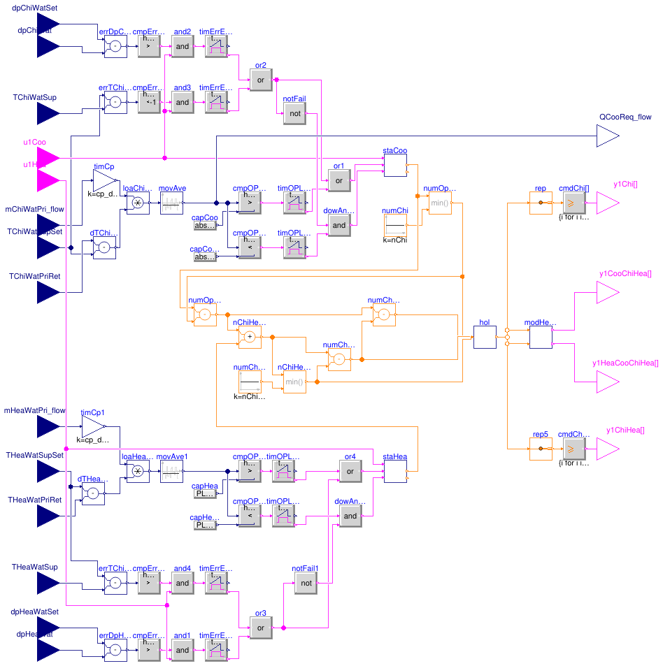
Information
This block implements the staging logic for the chillers and HRCs.
The units are staged in part based on an efficiency condition
using the operative part load ratio.
The units are also staged based on failsafe conditions using the CHW and HW
supply temperature and differential pressure.
For the sake of simplicity, equipment rotation (i.e. the possibility at a given
stage that either one unit or another unit can be operating) is not taken into account.
Plant stages
At cooling (resp. heating) stage #i, a number i
of units are operating in cooling (resp. heating) mode.
The cooling (resp. heating) stage #0 (no unit operating in
that given mode) is active whenever the plant is disabled based on the cooling
and heating Enable condition (see below) or when the plant is enabled
and has been staged down due to the efficiency or failsafe conditions.
The plant stage is given by the couple (cooling stage, heating stage).
The minimum runtime of each plant stage is set to 15 min.
Direct heat recovery mode
All HRCs are allowed to operate in direct heat recovery mode, that is when
their condenser is indexed to the HW loop and their evaporator is indexed to the
CHW loop.
Switching a HRC to operate in direct heat recovery mode is done on
a load requirement basis. This means that HRCs are first switched over
to cascading heating or cascading cooling mode. Only when all HRCs are operating
and when a new stage up event is initiated, an additional HRC is then switched
to operate in direct heat recovery mode.
As described in
Buildings.DHC.Plants.Combined.Controls.BaseClasses.ModeHeatRecoveryChiller
the HRC with the highest index that is not operating operating in cascading
cooling mode is the next to be switched into direct heat recovery mode.
For example, considering a plant with two chillers and three HRCs, the table below shows
the plant stages derived from this logic.
In this table, the chiller with index #i is denoted CHI#i,
the HRC with index #i is denoted HRC#i,
the units enumerated before (resp. after) the semicolon sign (:) operate
in cooling (resp. heating) mode, the units marked with a star (*) operate
in direct heat recovery mode.
| Heating stage ↓ Buildings.DHC.Plants.Cooling stage → |
0 |
1 |
2 |
3 |
4 |
5 |
|---|
| 0 |
N/A:
N/A |
CHI1:
N/A |
CHI1 & CHI2:
N/A |
CHI1 & CHI2 & HRC3:
N/A |
CHI1 & CHI2 & HRC3 & HRC2:
N/A |
CHI1 & CHI2 & HRC3 & HRC2 & HRC1:
N/A |
| 1 |
N/A:
HRC1 |
CHI1:
HRC1 |
CHI1 & CHI2:
HRC1 |
CHI1 & CHI2 & HRC3:
HRC1 |
CHI1 & CHI2 & HRC3 & HRC2:
HRC1 |
CHI1 & CHI2 & HRC3 & HRC2:
HRC1* |
| 2 |
N/A:
HRC1 & HRC2 |
CHI1:
HRC1 & HRC2 |
CHI1 & CHI2:
HRC1 & HRC2 |
CHI1 & CHI2 & HRC3:
HRC1 & HRC2 |
CHI1 & CHI2 & HRC3:
HRC1 & HRC2* |
CHI1 & CHI2 & HRC3:
HRC1* & HRC2* |
| 3 |
N/A:
HRC1 & HRC2 & HRC3 |
CHI1:
HRC1 & HRC2 & HRC3 |
CHI1 & CHI2:
HRC1 & HRC2 & HRC3 |
CHI1 & CHI2:
HRC1 & HRC2 & HRC3* |
CHI1 & CHI2:
HRC1 & HRC2* & HRC3* |
CHI1 & CHI2:
HRC1* & HRC2* & HRC3* |
Cooling and heating Enable condition
The cooling and heating Enable signals u1Coo and u1Hea
shall be computed outside of the plant model,
at least based on a time schedule and ideally in conjunction
with a signal representative of the demand such as the requests yielded by
the consumer control valves.
Based on those signals, the cooling (resp. heating) stage #1 is
activated whenever the cooling (resp. heating) Enable signal switches
to true and when cooling (resp. heating) has been disabled
for at least 15 min.
Operative part load ratio
The efficiency condition is based on the operative part load ratio
which is computed as the ratio of the required capacity
relative to design capacity of a given stage, which is the sum of the design capacity
of each unit active in a given stage.
The required capacity is calculated based on the primary mass flow rate and the
temperature difference between supply and primary return, and averaged over a
5-minute moving window.
Cooling and heating staging
A stage up event is initiated if any of the following conditions is true.
-
Efficiency condition: the operative part load ratio of the current stage
exceeds the value of the parameter PLRStaTra for 15 min.
-
Failsafe conditions: the CHW (resp. HW) supply temperature is 1 K
higher (resp. lower) than setpoint for 15 min, or
the CHW (resp. HW) differential pressure is 1.5E4 Pa lower than
setpoint for 15 min.
A stage down event is initiated if both of the following conditions are true.
-
Efficiency condition: the operative part load ratio of the next lower stage
falls below the value of the parameter PLRStaTra for 15 min.
-
Failsafe conditions: the failsafe stage up conditions are not true.
Parameters
| Type | Name | Default | Description |
|---|
| Real | PLRStaTra | 0.85 | Part load ratio triggering stage transition [1] |
| Real | cp_default | Buildings.Utilities.Psychrom... | Specific heat capacity of the fluid [J/(kg.K)] |
| CHW loop and cooling-only chillers |
| Integer | nChi | | Number of units operating at design conditions |
| Real | QChiWatChi_flow_nominal | | Cooling design heat flow rate of cooling-only chillers (all units) [W] |
| HW loop and heat recovery chillers |
| Integer | nChiHea | | Number of units operating at design conditions |
| Real | QChiWatCasCoo_flow_nominal | | Cooling design heat flow rate of HRC in cascading cooling mode (all units) [W] |
| Real | QChiWatCasCoo_flow_nominal_approx | | Cooling design heat flow rate of HRC in cascading cooling mode (all units), approximate for scaling [W] |
| Real | QHeaWat_flow_nominal | | Heating design heat flow rate (all units) [W] |
Connectors
| Type | Name | Description |
|---|
| input RealInput | mChiWatPri_flow | Primary CHW mass flow rate [kg/s] |
| input RealInput | TChiWatSupSet | CHW supply temperature setpoint [K] |
| input RealInput | TChiWatPriRet | Primary CHW return temperature [K] |
| input RealInput | mHeaWatPri_flow | Primary HW mass flow rate [kg/s] |
| input RealInput | THeaWatSupSet | HW supply temperature setpoint [K] |
| input RealInput | THeaWatPriRet | Primary HW return temperature [K] |
| input RealInput | TChiWatSup | CHW supply temperature [K] |
| input RealInput | dpChiWat | CHW loop differential pressure [Pa] |
| input RealInput | dpChiWatSet | CHW loop differential pressure setpoint [Pa] |
| input RealInput | THeaWatSup | HW supply temperature [K] |
| input RealInput | dpHeaWat | HW loop differential pressure [Pa] |
| input RealInput | dpHeaWatSet | HW loop differential pressure setpoint [Pa] |
| output RealOutput | QCooReq_flow | Plant required cooling capacity (>0) [W] |
| input BooleanInput | u1Coo | Cooling enable signal |
| input BooleanInput | u1Hea | Heating enable signal |
| output BooleanOutput | y1Chi[nChi] | Chiller On/Off command |
| output BooleanOutput | y1CooChiHea[nChiHea] | HRC cooling mode switchover command: true for cooling, false for heating |
| output BooleanOutput | y1ChiHea[nChiHea] | HRC On/Off command |
| output BooleanOutput | y1HeaCooChiHea[nChiHea] | HRC cooling mode switchover command: true for cooling, false for heating |
Modelica definition
block StagingPlant
parameter Integer nChi(
final min=1, start=1)
;
parameter Real QChiWatChi_flow_nominal(
final unit="W",
final quantity="HeatFlowRate")
;
parameter Integer nChiHea(
final min=1, start=1)
;
parameter Real PLRStaTra(unit="1") = 0.85
;
parameter Real QChiWatCasCoo_flow_nominal(
final unit="W",
final quantity="HeatFlowRate")
;
parameter Real QChiWatCasCoo_flow_nominal_approx(
final unit="W",
final quantity="HeatFlowRate")
;
parameter Real QHeaWat_flow_nominal(
final unit="W",
final quantity="HeatFlowRate")
;
parameter Real cp_default(
final quantity="SpecificHeatCapacity",
final unit="J/(kg.K)")=Buildings.Utilities.Psychrometrics.Constants.cpWatLiq
;
Buildings.Controls.OBC.CDL.Interfaces.RealInput mChiWatPri_flow(
final unit="kg/s")
;
Buildings.Controls.OBC.CDL.Interfaces.RealInput TChiWatSupSet(
final unit="K", displayUnit="degC")
;
Buildings.Controls.OBC.CDL.Interfaces.RealInput TChiWatPriRet(
final unit="K",
displayUnit="degC")
;
Buildings.Controls.OBC.CDL.Interfaces.RealInput mHeaWatPri_flow(
final unit="kg/s")
;
Buildings.Controls.OBC.CDL.Interfaces.RealInput THeaWatSupSet(
final unit="K", displayUnit="degC")
;
Buildings.Controls.OBC.CDL.Interfaces.RealInput THeaWatPriRet(
final unit="K",
displayUnit="degC")
;
Buildings.Controls.OBC.CDL.Interfaces.RealInput TChiWatSup(
final unit="K",
displayUnit="degC")
;
Buildings.Controls.OBC.CDL.Interfaces.RealInput dpChiWat(
final unit="Pa")
;
Buildings.Controls.OBC.CDL.Interfaces.RealInput dpChiWatSet(
final unit="Pa")
;
Buildings.Controls.OBC.CDL.Interfaces.RealInput THeaWatSup(
final unit="K",
displayUnit="degC")
;
Buildings.Controls.OBC.CDL.Interfaces.RealInput dpHeaWat(
final unit="Pa")
;
Buildings.Controls.OBC.CDL.Interfaces.RealInput dpHeaWatSet(
final unit="Pa")
;
Buildings.Controls.OBC.CDL.Interfaces.RealOutput QCooReq_flow(
final unit="W")
;
Buildings.Controls.OBC.CDL.Interfaces.BooleanInput u1Coo
;
Buildings.Controls.OBC.CDL.Interfaces.BooleanInput u1Hea
;
Buildings.Controls.OBC.CDL.Interfaces.BooleanOutput y1Chi[nChi]
;
Buildings.Controls.OBC.CDL.Interfaces.BooleanOutput y1CooChiHea[nChiHea]
;
Buildings.Controls.OBC.CDL.Interfaces.BooleanOutput y1ChiHea[nChiHea]
;
Buildings.Controls.OBC.CDL.Interfaces.BooleanOutput y1HeaCooChiHea[nChiHea]
;
Buildings.Controls.OBC.CDL.Reals.MovingAverage movAve(
final delta=300)
;
Buildings.Controls.OBC.CDL.Reals.Multiply loaChiWat
;
Buildings.Controls.OBC.CDL.Reals.Subtract dTChiWatPos
;
Buildings.Controls.OBC.CDL.Reals.Multiply loaHeaWat
;
Buildings.Controls.OBC.CDL.Reals.Subtract dTHeaWat ;
Buildings.Controls.OBC.CDL.Routing.IntegerScalarReplicator rep(
final nout=nChi)
;
Buildings.Controls.OBC.CDL.Integers.GreaterEqualThreshold cmdChi[nChi](
final t={i
for i
in 1:nChi})
;
Buildings.Controls.OBC.CDL.Reals.MultiplyByParameter timCp(
final k = cp_default)
;
Buildings.Controls.OBC.CDL.Reals.MultiplyByParameter timCp1(
final k = cp_default)
;
Buildings.Controls.OBC.CDL.Reals.MovingAverage movAve1(
final delta=300)
;
Buildings.Controls.OBC.CDL.Routing.IntegerScalarReplicator rep5(
final nout = nChiHea)
;
Buildings.Controls.OBC.CDL.Integers.GreaterEqualThreshold cmdChiHea[nChiHea](
final t={i
for i
in 1:nChiHea})
;
Buildings.Controls.OBC.CDL.Integers.Subtract numChiHeaCoo
;
Buildings.Controls.OBC.CDL.Integers.Sources.Constant numChiHea(
final k = nChiHea)
;
Buildings.Controls.OBC.CDL.Integers.Add nChiHeaAndCooUnb
;
Buildings.Controls.OBC.CDL.Integers.Subtract numChiCasCoo
;
Buildings.DHC.Plants.Combined.Controls.BaseClasses.ModeHeatRecoveryChiller modHeaCoo(
final nChiHea=nChiHea)
;
Buildings.Controls.OBC.CDL.Integers.Min nChiHeaHeaAndCoo
;
Buildings.Controls.OBC.CDL.Reals.Subtract errTChiWatSup
;
Buildings.Controls.OBC.CDL.Reals.Subtract errDpChiWat
;
Buildings.Controls.OBC.CDL.Reals.LessThreshold cmpErrLim(
final t=-1,
final h=1E-4)
;
Buildings.Controls.OBC.CDL.Reals.GreaterThreshold cmpErrLim1(
final t=1.5E4,
final h=1E-1)
;
Buildings.Controls.OBC.CDL.Logical.Timer timErrExcLim(
final t=15*60)
;
Buildings.Controls.OBC.CDL.Logical.Timer timErrExcLim1(
final t=15*60)
;
Buildings.Controls.OBC.CDL.Logical.Or or2
;
Buildings.Controls.OBC.CDL.Logical.And and2
;
Buildings.Controls.OBC.CDL.Logical.And and3
;
Buildings.DHC.Plants.Combined.Controls.BaseClasses.StageIndex staCoo(
final nSta=nChi + nChiHea, tSta=15*60)
;
Buildings.Controls.OBC.CDL.Reals.Greater cmpOPLRLimUp(
final h=-1E-4*(QChiWatChi_flow_nominal + QChiWatCasCoo_flow_nominal_approx)/2)
;
Buildings.Controls.OBC.CDL.Logical.Timer timOPLRExcLim(t=15*60)
;
Buildings.Controls.OBC.CDL.Logical.Or or1
;
Buildings.Controls.OBC.CDL.Integers.Min numOpeChi
;
Buildings.Controls.OBC.CDL.Integers.Sources.Constant numChi(
final k=nChi)
;
Buildings.Controls.OBC.CDL.Integers.Subtract numOpeCooChiHea
;
Buildings.Controls.OBC.CDL.Reals.Greater cmpOPLRLimUp1(
final h=1E-1)
;
Buildings.Controls.OBC.CDL.Logical.Timer timOPLRExcLim1(
final t=15*60)
;
Buildings.DHC.Plants.Combined.Controls.BaseClasses.StageIndex staHea(
final nSta=nChiHea,
tSta=15*60)
;
Buildings.Controls.OBC.CDL.Reals.Less cmpOPLRLimDow(
final h=1E-1)
;
Buildings.Controls.OBC.CDL.Logical.Timer timOPLRExcLim2(
t=15*60)
;
Buildings.Controls.OBC.CDL.Reals.Less cmpOPLRLimDow1(
h=-1E-4*(QChiWatChi_flow_nominal + QChiWatCasCoo_flow_nominal_approx)/2)
;
Buildings.Controls.OBC.CDL.Logical.Timer timOPLRExcLim3(
t=15*60)
;
Buildings.Controls.OBC.CDL.Logical.Not notFail
;
Buildings.Controls.OBC.CDL.Logical.And dowAndNotFail
;
Buildings.Controls.OBC.CDL.Reals.Subtract errTChiWatSup1
;
Buildings.Controls.OBC.CDL.Reals.Subtract errDpHeaWat
;
Buildings.Controls.OBC.CDL.Reals.GreaterThreshold cmpErrLim2(
t=+1, h=1E-4)
;
Buildings.Controls.OBC.CDL.Reals.GreaterThreshold cmpErrLim3(
t=1.5E4, h=1E-1)
;
Buildings.Controls.OBC.CDL.Logical.Timer timErrExcLim2(
t=15*60)
;
Buildings.Controls.OBC.CDL.Logical.Timer timErrExcLim3(
t=15*60)
;
Buildings.Controls.OBC.CDL.Logical.Or or3
;
Buildings.Controls.OBC.CDL.Logical.And and1
;
Buildings.Controls.OBC.CDL.Logical.And and4
;
Buildings.Controls.OBC.CDL.Logical.Not notFail1
;
Buildings.Controls.OBC.CDL.Logical.Or or4
;
Buildings.Controls.OBC.CDL.Logical.And dowAndNotFail1
;
Buildings.DHC.Plants.Combined.Controls.BaseClasses.IntegerArrayHold hol(
holdDuration=15*60,
nin=4)
;
Buildings.DHC.Plants.Combined.Controls.BaseClasses.StagingCapacity staCap(
final nChi=nChi,
final QChiWatChi_flow_nominal=QChiWatChi_flow_nominal,
final nChiHea=nChiHea,
final PLRStaTra=PLRStaTra,
final QChiWatCasCoo_flow_nominal=QChiWatCasCoo_flow_nominal,
final QHeaWat_flow_nominal=QHeaWat_flow_nominal)
;
equation
connect(dTChiWatPos.y, loaChiWat.u2);
connect(dTHeaWat.y, loaHeaWat.u2);
connect(THeaWatSupSet, dTHeaWat.u1);
connect(THeaWatPriRet, dTHeaWat.u2);
connect(rep.y, cmdChi.u);
connect(mChiWatPri_flow, timCp.u);
connect(timCp.y, loaChiWat.u1);
connect(mHeaWatPri_flow, timCp1.u);
connect(timCp1.y, loaHeaWat.u1);
connect(loaChiWat.y, movAve.u);
connect(loaHeaWat.y, movAve1.u);
connect(rep5.y, cmdChiHea.u);
connect(cmdChiHea.y, y1ChiHea);
connect(modHeaCoo.y1HeaCoo, y1HeaCooChiHea);
connect(numChiHea.y, nChiHeaHeaAndCoo.u2);
connect(nChiHeaAndCooUnb.y, nChiHeaHeaAndCoo.u1);
connect(nChiHeaAndCooUnb.y, numChiHeaCoo.u1);
connect(nChiHeaHeaAndCoo.y, numChiHeaCoo.u2);
connect(modHeaCoo.y1Coo, y1CooChiHea);
connect(numChiHeaCoo.y, numChiCasCoo.u2);
connect(TChiWatSupSet, errTChiWatSup.u1);
connect(dpChiWatSet, errDpChiWat.u1);
connect(errTChiWatSup.y, cmpErrLim.u);
connect(errDpChiWat.y, cmpErrLim1.u);
connect(timErrExcLim1.passed, or2.u1);
connect(timErrExcLim.passed, or2.u2);
connect(cmpErrLim1.y, and2.u1);
connect(and2.y, timErrExcLim1.u);
connect(cmpErrLim.y, and3.u1);
connect(and3.y, timErrExcLim.u);
connect(u1Coo, and3.u2);
connect(u1Coo, and2.u2);
connect(cmdChi.y, y1Chi);
connect(u1Coo, staCoo.u1);
connect(cmpOPLRLimUp.y, timOPLRExcLim.u);
connect(or2.y, or1.u1);
connect(or1.y, staCoo.u1Up);
connect(timOPLRExcLim.passed, or1.u2);
connect(numChi.y, numOpeChi.u2);
connect(staCoo.idxSta, numOpeChi.u1);
connect(staCoo.idxSta, numOpeCooChiHea.u1);
connect(numOpeChi.y, numOpeCooChiHea.u2);
connect(numOpeCooChiHea.y, nChiHeaAndCooUnb.u1);
connect(cmpOPLRLimUp1.y, timOPLRExcLim1.u);
connect(u1Hea, staHea.u1);
connect(cmpOPLRLimDow.y, timOPLRExcLim2.u);
connect(cmpOPLRLimDow1.y, timOPLRExcLim3.u);
connect(or2.y, notFail.u);
connect(dowAndNotFail.y, staCoo.u1Dow);
connect(timOPLRExcLim3.passed, dowAndNotFail.u2);
connect(notFail.y, dowAndNotFail.u1);
connect(staHea.idxSta, nChiHeaAndCooUnb.u2);
connect(numOpeCooChiHea.y, numChiCasCoo.u1);
connect(movAve.y, cmpOPLRLimUp.u1);
connect(movAve.y, cmpOPLRLimDow1.u1);
connect(movAve1.y, cmpOPLRLimUp1.u1);
connect(movAve1.y, cmpOPLRLimDow.u1);
connect(TChiWatSupSet, dTChiWatPos.u2);
connect(TChiWatPriRet, dTChiWatPos.u1);
connect(dpHeaWatSet, errDpHeaWat.u1);
connect(errTChiWatSup1.y, cmpErrLim2.u);
connect(errDpHeaWat.y, cmpErrLim3.u);
connect(cmpErrLim3.y,and1. u1);
connect(and1.y,timErrExcLim3. u);
connect(cmpErrLim2.y, and4.u1);
connect(and4.y, timErrExcLim2.u);
connect(or3.y, notFail1.u);
connect(THeaWatSupSet, errTChiWatSup1.u1);
connect(timErrExcLim2.passed, or3.u1);
connect(timErrExcLim3.passed, or3.u2);
connect(u1Hea, and4.u2);
connect(u1Hea, and1.u2);
connect(timOPLRExcLim1.passed, or4.u1);
connect(or3.y, or4.u2);
connect(timOPLRExcLim2.passed, dowAndNotFail1.u1);
connect(notFail1.y, dowAndNotFail1.u2);
connect(dowAndNotFail1.y, staHea.u1Dow);
connect(or4.y, staHea.u1Up);
connect(numOpeChi.y, hol.u[1]);
connect(numChiCasCoo.y, hol.u[2]);
connect(numChiHeaCoo.y, hol.u[3]);
connect(nChiHeaHeaAndCoo.y, hol.u[4]);
connect(hol.y[1], rep.u);
connect(hol.y[2], modHeaCoo.nCasCoo);
connect(hol.y[3], modHeaCoo.nHeaCoo);
connect(hol.y[4], rep5.u);
connect(movAve.y, QCooReq_flow);
connect(dpChiWat, errDpChiWat.u2);
connect(TChiWatSup, errTChiWatSup.u2);
connect(THeaWatSup, errTChiWatSup1.u2);
connect(dpHeaWat, errDpHeaWat.u2);
connect(staCoo.preIdxSta, staCap.uCooPreIdxSta);
connect(staHea.preIdxSta, staCap.uHeaPreIdxSta);
connect(staCap.yCoo, cmpOPLRLimUp.u2);
connect(staCap.yCooLow, cmpOPLRLimDow1.u2);
connect(staCap.yHea, cmpOPLRLimUp1.u2);
connect(staCap.yHeaLow, cmpOPLRLimDow.u2);
end StagingPlant;
Pump staging
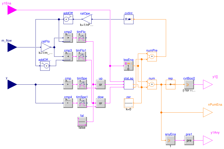
Information
This block implements the logic for staging the lag pump of
a multiple-pump group.
The first staging criterion is optional and is based on ratFlo,
the ratio of current flow rate to design flow rate.
The lag pump is enabled whenever any of the following is true.
- The pump speed command is higher than
yUp for 5 min.
- Optionally if
have_flowCriterion is set to true, the ratio ratFlo
is higher than n / nPum - 0.03 for 10 min, where n is the number
of operating pumps and nPum is the number of pumps operating at design conditions.
The lag pump is disabled whenever any of the following is true.
- The lead pump is disabled.
- The pump speed command is lower than
yDow for 5 min.
- Optionally if
have_flowCriterion is set to true, the ratio ratFlo
is higher than (n - 1) / nPum - 0.03 for 10 min.
Parameters
| Type | Name | Default | Description |
|---|
| Boolean | have_flowCriterion | true | Set to true for flow criterion in conjunction with speed criterion |
| Integer | nPum | | Number of pumps |
| Real | yDow | 0.30 | Low speed limit for staging down |
| Real | yUp | 0.99 | High speed limit for staging up |
| Nominal condition |
| Real | m_flow_nominal | 1 | Loop design mass flow rate (all pumps) [kg/s] |
Connectors
| Type | Name | Description |
|---|
| input BooleanInput | y1Ena | Lead pump Enable signal (e.g. based on isolation valve opening command) |
| input RealInput | m_flow | Mass flow rate as measured by the loop flow meter [kg/s] |
| input RealInput | y | Commanded speed [1] |
| output BooleanOutput | y1[nPum] | Start signal (VFD Run or motor starter contact) |
| output IntegerOutput | nPumEna | Number of pumps that are enabled |
| output BooleanOutput | y1Any | Return true if any pump enabled (left limit to avoid direct feedback) |
Modelica definition
block StagingPump
parameter Boolean have_flowCriterion=true
;
parameter Integer nPum(
final min=1,
start=1)
;
parameter Real m_flow_nominal(
final unit="kg/s",
final quantity="MassFlowRate")=1
;
parameter Real yDow=0.30
;
parameter Real yUp=0.99
;
Buildings.Controls.OBC.CDL.Interfaces.BooleanInput y1Ena
;
Buildings.Controls.OBC.CDL.Interfaces.RealInput m_flow(
final unit="kg/s")
if have_flowCriterion
;
Buildings.Controls.OBC.CDL.Interfaces.RealInput y(
final unit="1")
;
Buildings.Controls.OBC.CDL.Interfaces.BooleanOutput y1[nPum]
;
Buildings.Controls.OBC.CDL.Interfaces.IntegerOutput nPumEna
;
Buildings.Controls.OBC.CDL.Interfaces.BooleanOutput y1Any
;
Buildings.Controls.OBC.CDL.Reals.GreaterThreshold cmp(
final t=yUp, h=1e-3)
;
Buildings.Controls.OBC.CDL.Logical.Timer timSpe(t=5*60)
;
Buildings.Controls.OBC.CDL.Reals.MultiplyByParameter ratFlo(
final k=1/m_flow_nominal)
if have_flowCriterion
;
Buildings.Controls.OBC.CDL.Reals.Greater cmp2(h=1e-3)
if have_flowCriterion
;
Buildings.Controls.OBC.CDL.Reals.AddParameter addOff(p=-0.03)
if have_flowCriterion
;
Buildings.Controls.OBC.CDL.Logical.Timer timFlo(t=10*60)
if have_flowCriterion
;
Buildings.Controls.OBC.CDL.Logical.Or up
;
Buildings.Controls.OBC.CDL.Reals.Less cmp3(h=1e-3)
if have_flowCriterion
;
Buildings.Controls.OBC.CDL.Logical.Timer timFlo1(t=10*60)
if have_flowCriterion
;
Buildings.Controls.OBC.CDL.Reals.LessThreshold cmp4(
final t=yDow, h=1e-3)
;
Buildings.Controls.OBC.CDL.Logical.Timer timSpe1(t=5*60)
;
Buildings.Controls.OBC.CDL.Logical.Or dow
;
Buildings.Controls.OBC.CDL.Reals.MultiplyByParameter ratOpeDsg(
final k=1/nPum)
;
Buildings.Controls.OBC.CDL.Integers.GreaterEqualThreshold cvtBoo[nPum](
final t={i
for i
in 1:nPum})
;
Buildings.Controls.OBC.CDL.Routing.IntegerScalarReplicator rep(
final nout=nPum) ;
Buildings.DHC.Plants.Combined.Controls.BaseClasses.StageIndex staLag(
final nSta=
max(1, nPum - 1), tSta=30)
if nPum>1
;
Buildings.Controls.OBC.CDL.Conversions.IntegerToReal cvtInt ;
Buildings.Controls.OBC.CDL.Reals.AddParameter addOffLowSta(
final p=-1/nPum)
if have_flowCriterion
;
Buildings.Controls.OBC.CDL.Conversions.BooleanToInteger leaEna
;
Buildings.Controls.OBC.CDL.Integers.Add num ;
Buildings.Controls.OBC.CDL.Integers.Add numPre ;
Buildings.Controls.OBC.CDL.Integers.Sources.Constant zer(
final k=0)
if nPum==1
;
Buildings.Controls.OBC.CDL.Logical.Sources.Constant fal(
final k=false)
if not have_flowCriterion
;
Buildings.Controls.OBC.CDL.Integers.GreaterEqualThreshold anyEna(
final t=1)
;
Buildings.Controls.OBC.CDL.Logical.Pre pre1
;
equation
connect(y, cmp.u);
connect(cmp.y, timSpe.u);
connect(ratFlo.y, cmp2.u1);
connect(addOff.y, cmp2.u2);
connect(timFlo.passed, up.u1);
connect(ratFlo.y, cmp3.u1);
connect(y, cmp4.u);
connect(cmp4.y, timSpe1.u);
connect(timFlo1.passed,dow. u1);
connect(addOff.u, ratOpeDsg.y);
connect(rep.y, cvtBoo.u);
connect(cmp2.y, timFlo.u);
connect(cmp3.y, timFlo1.u);
connect(timSpe.passed, up.u2);
connect(timSpe1.passed,dow. u2);
connect(y1Ena, staLag.u1);
connect(cvtInt.y, ratOpeDsg.u);
connect(cvtBoo.y, y1);
connect(addOff.y, addOffLowSta.u);
connect(addOffLowSta.y, cmp3.u2);
connect(y1Ena, leaEna.u);
connect(dow.y, staLag.u1Dow);
connect(num.y, rep.u);
connect(staLag.idxSta, num.u2);
connect(leaEna.y, num.u1);
connect(numPre.y, cvtInt.u);
connect(leaEna.y, numPre.u1);
connect(staLag.preIdxSta, numPre.u2);
connect(zer.y, num.u2);
connect(zer.y, numPre.u2);
connect(up.y, staLag.u1Up);
connect(fal.y, dow.u1);
connect(fal.y, up.u1);
connect(num.y, nPumEna);
connect(anyEna.y, pre1.u);
connect(pre1.y, y1Any);
connect(num.y, anyEna.u);
connect(m_flow, ratFlo.u);
end StagingPump;
Tank charge fraction
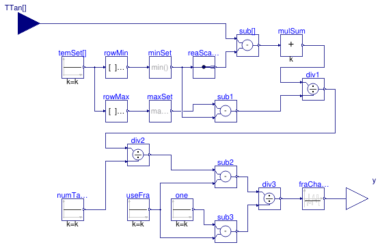
Information
The tank charge fraction y is computed as the
5-minute moving average of the following expression:
(∑i (TTani - min(TTanSet)) /
(max(TTanSet) - min(TTanSet)) / nTTan - fraUslTan) /
(1 - fraUslTan),
where TTani is the measurement from the i-th temperature sensor
along the vertical axis of the tank,
TTanSet are the tank temperature setpoints (two values for each tank cycle),
nTTan is the number of temperature sensors along the vertical axis of the tank,
fraUslTan is the useless fraction of the tank which is computed as
shown in
Buildings.DHC.Plants.Combined.Controls.BaseClasses.ModeCondenserLoop.
Parameters
| Type | Name | Default | Description |
|---|
| Real | TTanSet[2, 2] | | Tank temperature setpoints: 2 cycles with 2 setpoints [K] |
| Real | fraUslTan | | Useless fraction of TES [1] |
Connectors
| Type | Name | Description |
|---|
| input RealInput | TTan[nTTan] | TES tank temperature [K] |
| output RealOutput | y | Tank charge fraction [1] |
Modelica definition
block TankChargeFraction
parameter Integer nTTan
;
parameter Real TTanSet[2, 2](
each final quantity="ThermodynamicTemperature",
each final unit="K",
each displayUnit="degC")
;
parameter Real fraUslTan(unit="1")
;
Buildings.Controls.OBC.CDL.Interfaces.RealInput TTan[nTTan](
final unit=
fill("K",nTTan),
displayUnit=
fill("degC", nTTan)) ;
Buildings.Controls.OBC.CDL.Interfaces.RealOutput y(
final unit="1") ;
Buildings.Controls.OBC.CDL.Reals.MatrixMax rowMax(
final nRow=2,
final nCol=2)
;
Buildings.Controls.OBC.CDL.Reals.MatrixMin rowMin(
final nRow=2,
final nCol=2)
;
Buildings.Controls.OBC.CDL.Reals.MultiMax maxSet(
final nin=2) ;
Buildings.Controls.OBC.CDL.Reals.MultiMin minSet(
final nin=2) ;
Buildings.Controls.OBC.CDL.Reals.Sources.Constant temSet[2,2](
final k=TTanSet)
;
Buildings.Controls.OBC.CDL.Reals.Sources.Constant numTanTemPoi(
final k=nTTan)
;
Buildings.Controls.OBC.CDL.Reals.Sources.Constant useFra(
final k=fraUslTan)
;
Buildings.Controls.OBC.CDL.Routing.RealScalarReplicator reaScaRep(
final nout=nTTan)
;
Buildings.Controls.OBC.CDL.Reals.Subtract sub[nTTan]
;
Buildings.Controls.OBC.CDL.Reals.MultiSum mulSum(
final nin=nTTan) ;
Buildings.Controls.OBC.CDL.Reals.Subtract sub1 ;
Buildings.Controls.OBC.CDL.Reals.Divide div1 ;
Buildings.Controls.OBC.CDL.Reals.Divide div2 ;
Buildings.Controls.OBC.CDL.Reals.Subtract sub2
;
Buildings.Controls.OBC.CDL.Reals.Sources.Constant one(
final k=1)
;
Buildings.Controls.OBC.CDL.Reals.Subtract sub3
;
Buildings.Controls.OBC.CDL.Reals.Divide div3
;
Buildings.Controls.OBC.CDL.Reals.MovingAverage fraChaTan(
final delta=5*60)
;
equation
connect(temSet.y,rowMax. u);
connect(temSet.y,rowMin. u);
connect(rowMax.y,maxSet. u);
connect(rowMin.y,minSet. u);
connect(minSet.y, reaScaRep.u);
connect(reaScaRep.y, sub.u2);
connect(TTan, sub.u1);
connect(sub.y, mulSum.u);
connect(maxSet.y, sub1.u1);
connect(minSet.y, sub1.u2);
connect(sub1.y, div1.u2);
connect(mulSum.y, div1.u1);
connect(numTanTemPoi.y, div2.u2);
connect(div1.y, div2.u1);
connect(div2.y, sub2.u1);
connect(useFra.y, sub2.u2);
connect(one.y, sub3.u1);
connect(useFra.y, sub3.u2);
connect(sub2.y, div3.u1);
connect(sub3.y, div3.u2);
connect(div3.y, fraChaTan.u);
connect(fraChaTan.y, y);
end TankChargeFraction;
Rate of change of the tank charge fraction
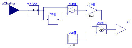
Information
The rate of change of the tank charge fraction y is computed
over several time periods (10, 30, 120, 240
and 360 min) as:
uChaFra(Δt) = (uChaFra(t) - uChaFra(t - Δt)) / Δt * 3600,
where Δt is the time period in seconds.
Parameters
| Type | Name | Default | Description |
|---|
| Real | timPer[5] | {10,30,120,240,360}*60 | Time periods [s] |
Connectors
| Type | Name | Description |
|---|
| input RealInput | uChaFra | Tank charge fraction [1] |
| output RealOutput | y[nTimPer] | Tank charge fraction [1/h] |
Modelica definition
block TankChargeFractionRate
parameter Real timPer[5](
final quantity=
fill("Time",5),
final unit=
fill("s",5))={10,30,120,240,360} * 60
;
Buildings.Controls.OBC.CDL.Interfaces.RealInput uChaFra(
final unit="1")
;
Buildings.Controls.OBC.CDL.Interfaces.RealOutput y[nTimPer](
final unit=
fill("1/h",nTimPer))
;
Buildings.DHC.Plants.Combined.Controls.BaseClasses.Delay del[nTimPer](
final
delayTime=timPer)
;
Buildings.Controls.OBC.CDL.Routing.RealScalarReplicator reaScaRep(
final nout=nTimPer)
;
Buildings.Controls.OBC.CDL.Reals.Subtract sub[nTimPer]
;
Buildings.Controls.OBC.CDL.Reals.Sources.Constant con[nTimPer](
final k=timPer)
;
Buildings.Controls.OBC.CDL.Reals.MultiplyByParameter gai[nTimPer](
final k=
fill(3600, nTimPer)) ;
Buildings.Controls.OBC.CDL.Reals.Divide div1[nTimPer]
;
protected
parameter Integer nTimPer=
size(timPer,1)
;
equation
connect(uChaFra, reaScaRep.u);
connect(reaScaRep.y, sub.u1);
connect(del.y, sub.u2);
connect(reaScaRep.y, del.u);
connect(sub.y, gai.u);
connect(con.y, div1.u2);
connect(gai.y, div1.u1);
connect(div1.y, y);
end TankChargeFractionRate;
Block that determines the tank cycle flag
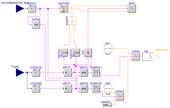
Information
The tank operating conditions should match the operating limits and selection
conditions of the chillers and HRCs.
The highest temperature (at the top of the tank) should be limited by the
maximum evaporator entering temperature per manufacturer’s recommendations.
The lowest temperature (at the bottom of the tank) should be limited by the
design CHW supply temperature.
This gives the tank maximum ΔT and the actual storage capacity.
However, this value is likely above the maximum ΔT that chillers
and HRCs can achieve across the condenser or evaporator barrel (typically
11 K). Therefore, in order to fully leverage the TES capacity,
two temperature cycles are needed.
The first tank cycle (higher temperature setpoint) is activated whenever
all of the following conditions are true.
-
All tank temperature sensors measure a value higher than the mean setpoint value
of the second tank cycle for 5 min.
-
The flow rate out of the lower port of the tank is positive (tank is charging)
for 5 min.
The second tank cycle (lower temperature setpoint) is activated
whenever both of the following conditions are true.
-
All tank temperature sensors measure a value lower than the mean setpoint value
of the first tank cycle for 5 min.
-
The flow rate out of the lower port of the tank is negative (tank is discharging)
for 5 min.
At initial time the tank cycle flag is set based on the tank temperature condition
only from the above two clauses without a time delay.
If neither condition is true, the tank cycle flag is set based on the flow condition
only in the above two clauses without a time delay.
The minimum runtime of each tank cycle is fixed at 30 min.
Parameters
| Type | Name | Default | Description |
|---|
| Real | mConWatHexCoo_flow_nominal | | Design total CW mass flow rate through condenser barrels (all units) [kg/s] |
| CW loop, TES tank and heat pumps |
| Real | TTanSet[2, 2] | | Tank temperature setpoints: 2 cycles with 2 setpoints [K] |
Connectors
| Type | Name | Description |
|---|
| input RealInput | mConWatOutTan_flow | Mass flow rate out of lower port of TES tank (>0 when charging) [kg/s] |
| input RealInput | TTan[nTTan] | TES tank temperature [K] |
| output IntegerOutput | idxCycTan | Index of active tank cycle |
Modelica definition
block TankCycle
parameter Real mConWatHexCoo_flow_nominal(
final unit="kg/s",
final quantity="MassFlowRate")
;
parameter Real TTanSet[2, 2](
each final quantity="ThermodynamicTemperature",
each final unit="K",
each displayUnit="degC")
;
parameter Integer nTTan=0
;
Buildings.Controls.OBC.CDL.Interfaces.RealInput mConWatOutTan_flow(
final unit="kg/s")
;
Buildings.Controls.OBC.CDL.Interfaces.RealInput TTan[nTTan](
each final unit="K",
each displayUnit="degC")
;
Buildings.Controls.OBC.CDL.Interfaces.IntegerOutput idxCycTan(
final min=1,
final max=2)
;
Buildings.Controls.OBC.CDL.Reals.GreaterThreshold criTem1[nTTan](
each t=
sum(TTanSet[2])/2,
each h=1E-4)
;
Buildings.Controls.OBC.CDL.Logical.MultiAnd allCriTem1(
final nin=nTTan)
;
Buildings.Controls.OBC.CDL.Reals.GreaterThreshold criFlo1(
final t=1E-3*mConWatHexCoo_flow_nominal,
h=1E-3*mConWatHexCoo_flow_nominal/2)
;
Buildings.Controls.OBC.CDL.Reals.LessThreshold criTem2[nTTan](
each t=
sum(TTanSet[1])/2,
each h=1E-4)
;
Buildings.Controls.OBC.CDL.Logical.MultiAnd allCriTem2(
final nin=nTTan)
;
Buildings.Controls.OBC.CDL.Conversions.BooleanToInteger booToInt(
final integerTrue=1,
final integerFalse=2)
;
Buildings.Controls.OBC.CDL.Logical.Or or2
;
Buildings.Controls.OBC.CDL.Conversions.BooleanToInteger booToInt3(
final integerTrue=2,
final integerFalse=0)
;
Buildings.Controls.OBC.CDL.Conversions.BooleanToInteger booToInt4(
final integerTrue=1,
final integerFalse=0)
;
Buildings.Controls.OBC.CDL.Integers.Max maxInt1
;
Buildings.Controls.OBC.CDL.Logical.And allCri2
;
Buildings.Controls.OBC.CDL.Logical.And allCri1
;
Buildings.Controls.OBC.CDL.Integers.Switch idxIni
;
Buildings.Controls.OBC.CDL.Logical.Timer timAllCri1(t=5*60)
;
Buildings.Controls.OBC.CDL.Logical.Timer timAllCri2(t=5*60)
;
Buildings.Controls.OBC.CDL.Integers.Switch intSwi
;
Buildings.Controls.OBC.CDL.Integers.Sources.Constant idx1(
final k=1)
;
Buildings.Controls.OBC.CDL.Integers.Switch intSwi1
;
Buildings.Controls.OBC.CDL.Integers.Sources.Constant idx2(
final k=2)
;
Buildings.Controls.OBC.CDL.Logical.Not criFlo2
;
Buildings.DHC.Plants.Combined.Controls.BaseClasses.IntegerArrayHold hol(
holdDuration=30*60,
nin=1)
;
Buildings.Controls.OBC.CDL.Integers.GreaterThreshold intGreThr(
final t=1)
;
Buildings.Controls.OBC.CDL.Logical.Pre pre1 ;
Buildings.Controls.OBC.CDL.Conversions.BooleanToInteger booToInt1(
final integerTrue=2,
final integerFalse=1)
;
initial equation
pre(idxCycTan)=idxIni.y;
equation
connect(criTem1.y, allCriTem1.u);
connect(TTan, criTem2.u);
connect(TTan, criTem1.u);
connect(criTem2.y, allCriTem2.u);
connect(allCriTem2.y, booToInt3.u);
connect(allCriTem1.y, booToInt4.u);
connect(allCriTem1.y, allCri1.u1);
connect(allCriTem2.y, allCri2.u1);
connect(maxInt1.u2, booToInt3.y);
connect(booToInt4.y, maxInt1.u1);
connect(allCriTem1.y, or2.u1);
connect(allCriTem2.y, or2.u2);
connect(or2.y, idxIni.u2);
connect(maxInt1.y, idxIni.u1);
connect(criFlo1.y, booToInt.u);
connect(booToInt.y, idxIni.u3);
connect(mConWatOutTan_flow, criFlo1.u);
connect(allCri1.y, timAllCri1.u);
connect(allCri2.y, timAllCri2.u);
connect(timAllCri1.passed, intSwi.u2);
connect(idx1.y, intSwi.u1);
connect(timAllCri2.passed, intSwi1.u2);
connect(idx2.y, intSwi1.u1);
connect(intSwi1.y, intSwi.u3);
connect(criFlo1.y, criFlo2.u);
connect(hol.y[1], idxCycTan);
connect(criFlo1.y, allCri1.u2);
connect(criFlo2.y, allCri2.u2);
connect(intSwi.y, hol.u[1]);
connect(hol.y[1], intGreThr.u);
connect(intGreThr.y, pre1.u);
connect(pre1.y, booToInt1.u);
connect(booToInt1.y, intSwi1.u3);
end TankCycle;
Controller for chiller and HRC condenser and evaporator valves
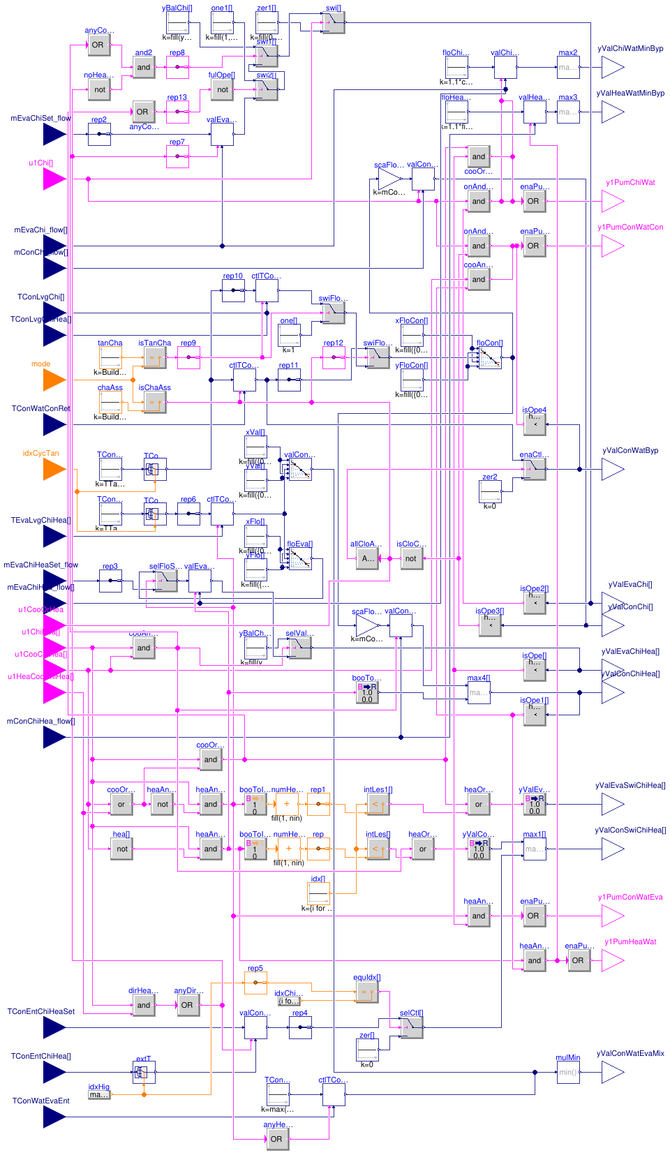
Information
This block implements the control logic for the chiller isolation valves,
the HRC isolation and switchover valves, the CHW and HW minimum flow
bypass valves, the HRC evaporator CW mixing valve, and the
CW chiller bypass valve.
It also computes the lead pump Enable signal for the CHW, HW, CWC and CWE
pump groups.
Chiller evaporator isolation valve
When a chiller is enabled, the valve position is controlled as follows.
-
If no HRC is concurrently operating and connected to the CHW loop,
the valve is commanded to a fully open position,
-
If any HRC is concurrently operating in cascading cooling mode,
but no HRC is in direct heat recovery mode, the valve is
commanded to a fixed position ensuring flow balancing proportionally to
design flow.
-
If any HRC is concurrently operating in direct heat recovery mode, the valve
is modulated with a control loop tracking an evaporator flow setpoint
which is reset as described hereunder.
The loop output is mapped to a valve position of 10 % (resp. 100 %)
at 0 % (resp. 100 %) output signal.
The loop is biased to launch from 100 %.
Otherwise, the valve is commanded to a closed position.
Chiller evaporator flow setpoint
The setpoint is computed based on the logic implemented in
Buildings.DHC.Plants.Combined.Controls.BaseClasses.DirectHeatRecovery.
Chiller condenser isolation valve
When a chiller is enabled, the condenser isolation valve is modulated with a
control loop tracking a condenser flow setpoint which is reset as described hereunder.
The loop output is mapped to a valve position of 10 % (resp. 100 %)
at 0 % (resp. 100 %) output signal.
The loop is biased to launch from 100 %.
Otherwise, the valve is commanded to a closed position.
Chiller condenser flow setpoint
The condenser flow setpoint varies based on the condenser loop mode and
on the tank cycle index.
-
When the condenser loop mode is Charge Assist, a control loop
maintains the condenser loop return temperature at a target setpoint
equal to the highest temperature setpoint of the active tank cycle.
The loop output is mapped to a flow setpoint of 10 % (resp. 100 %)
of design flow at 0 % (resp. 100 %) output signal.
The loop is biased to launch from 20 %.
-
When the condenser loop mode is Tank Charge/Discharge, a control loop
maintains the chiller condenser leaving temperature at target setpoint equal
to the highest temperature setpoint of the active tank cycle.
The loop output is mapped to a flow setpoint of 5 % (resp. 100 %)
of design flow at 0 % (resp. 100 %) output signal.
The loop is biased to launch from 50 %.
-
When the condenser loop mode is Heat Rejection, the condenser flow setpoint
is set at design value.
HRC evaporator isolation valve
When a HRC is enabled, the valve position is controlled as follows.
-
If the HRC is operating in cascading cooling mode, the valve is commanded
to a fixed position ensuring flow balancing proportionally to
design flow.
-
If the HRC is operating either in cascading heating mode or in direct
heat recovery mode, the valve is modulated with a control loop tracking
an evaporator flow setpoint which is reset as described hereunder.
The loop output is mapped to a valve position of 10 % (resp. 100 %)
at 0 % (resp. 100 %) output signal.
The loop is biased to launch from 100 %.
Otherwise, the valve is commanded to a closed position.
HRC evaporator flow setpoint
In direct heat recovery mode, the setpoint is reset based on the logic implemented in
Buildings.DHC.Plants.Combined.Controls.BaseClasses.DirectHeatRecovery.
In cascading heating mode, the setpoint is reset with a control loop
that maintains the evaporator leaving temperature at target setpoint
equal to the lowest temperature setpoint of the active tank cycle.
The loop output is mapped as follows.
From 0 % to 50 %, the HRC evaporator
CW mixing valve commanded position is reset from 0 % (full bypass flow)
to 100 % (no bypass flow).
From 50 % to 100 %, the
evaporator flow setpoint is reset from minimum to design value.
The loop is biased to launch from 75 %.
When disabled, the loop output is set to 75 % to
ensure that the HRC evaporator CW mixing valve is fully open
(no bypass flow).
HRC condenser isolation valve
When a HRC is enabled, the valve position is controlled as follows.
-
If the HRC condenser is indexed to the HW loop (cascading heating or
direct heat recovery mode), the valve is commanded to a fully open
position.
-
If the HRC condenser is indexed to the CW loop (cascading cooling mode),
the valve is modulated with a control loop tracking a condenser flow setpoint
which is reset based
on the same logic as for the chiller condenser flow setpoint (see above).
The loop output is mapped to a valve position of 10 % (resp. 100 %)
at 0 % (resp. 100 %) output signal.
The loop is biased to launch from 100 %.
Otherwise, the valve is commanded to a closed position.
HRC condenser and evaporator switchover valve
Each valve is commanded to a fully open or fully closed position depending
on the valve index and the current operating mode of the HRC (cascading cooling,
cascading heating or direct heat recovery).
In addition, the condenser switchover valve indexed to the HRC which is nearest to the
interconnection with the condenser loop (highest index) and which is operating
in direct heat recovery mode is modulated with a control loop tracking
the condenser entering temperature.
The condenser entering temperature setpoint is reset based on the logic implemented in
Buildings.DHC.Plants.Combined.Controls.BaseClasses.DirectHeatRecovery.
This allows false loading the HRC that is controlled to meet the HW supply
temperature setpoint in direct heat recovery mode, and thus meeting
the CHW supply temperature setpoint simultaneously.
HRC evaporator CW mixing valve
The valve is modulated based on two control loops:
the HRC evaporator leaving temperature control loop (see the section
HRC evaporator flow setpoint) and another control loop that maintains
the HRC evaporator entering water temperature below the highest tank temperature
setpoint.
This latter control loop is enabled when any HRC is operating in cascading
heating mode.
When the loop is enabled, the loop output is mapped to a valve position
of 100 % (resp. 0 %) at 0 % (resp. 100 %)
output signal.
When the loop is disabled, the loop output is set to 100 % (no bypass flow).
The valve control signal is the minimum (maximum bypass flow) of the resulting
signals of those two control loops.
CHW and HW minimum flow bypass valve
Each chiller and HRC has its own CHW (resp. HW) minimum flow control loop.
The loop is enabled whenever the unit's evaporator (resp. condenser) is indexed
to the CHW (resp. HW) loop and its evaporator (resp. condenser) isolation valve
is commanded open (with a threshold of 10 %).
When enabled, each loop tracks a flow setpoint equal to 1.1 times the
minimum CHW (resp. HW) flow rate.
When disabled, each loop output is set to 0 %.
The valve control signal is the maximum (maximum bypass flow) of the resulting
signals of all control loops.
CW chiller bypass valve
The valve control is enabled when the plant is enabled either in cooling or
heating mode, the Charge Assist mode is active and
all chiller condenser isolation valves are closed (based on their
commanded position).
When the valve control is enabled the valve position is modulated
by the same control loop used to maintain the condenser loop return
temperature at a target setpoint equal to the highest temperature
setpoint of the active tank cycle (see the section "Chiller condenser flow setpoint").
Otherwise, the valve is commanded to a closed position.
CHW, HW, CWC, CWE lead pump
The lead pump of each loop is enabled whenever any chiller or HRC is indexed
to the loop and the corresponding evaporator or condenser isolation valve is
commanded open (with a threshold of 10 %).
In addition, the CWC lead pump may also be enabled if the CW chiller
bypass valve is commanded open.
Parameters
| Type | Name | Default | Description |
|---|
| Real | yBalEvaChi | if dpEvaChiHea_nominal + dpV... | Chiller evaporator isolation valve opening for flow balancing with HRC |
| Real | yBalEvaChiHea | if dpEvaChi_nominal + dpValE... | HRC evaporator isolation valve opening for flow balancing with chiller |
| CHW loop and cooling-only chillers |
| Integer | nChi | | Number of units operating at design conditions |
| Real | mChiWatChi_flow_nominal | | Chiller CHW design mass flow rate (value will be used for each unit) [kg/s] |
| Real | mChiWatChi_flow_min | | Chiller CHW minimum mass flow rate (value will be used for each unit) [kg/s] |
| Real | mConWatChi_flow_nominal | | Chiller CW design mass flow rate (value will be used for each unit) [kg/s] |
| Real | dpEvaChi_nominal | | Chiller evaporator design pressure drop (value will be used for each unit) [Pa] |
| Real | dpValEvaChi_nominal | | Chiller evaporator isolation valve design pressure drop (value will be used for each unit) [Pa] |
| HW loop and heat recovery chillers |
| Integer | nChiHea | | Number of units operating at design conditions |
| Real | mChiWatChiHea_flow_nominal | | HRC CHW design mass flow rate (value will be used for each unit) [kg/s] |
| Real | mChiWatChiHea_flow_min | | HRC CHW minimum mass flow rate (value will be used for each unit) [kg/s] |
| Real | mConWatChiHea_flow_nominal | | HRC CW design mass flow rate (value will be used for each unit) [kg/s] |
| Real | mHeaWatChiHea_flow_min | | Chiller HW minimum mass flow rate (value will be used for each unit) [kg/s] |
| Real | dpEvaChiHea_nominal | | Design chiller evaporator pressure drop (value will be used for each unit) [Pa] |
| Real | dpValEvaChiHea_nominal | | HRC evaporator isolation valve design pressure drop (value will be used for each unit) [Pa] |
| CW loop, TES tank and heat pumps |
| Real | TTanSet[2, 2] | | Tank temperature setpoints: 2 cycles with 2 setpoints [K] |
| Control parameters |
| Real | k | 0.01 | Gain of controller |
| Real | Ti | 60 | Time constant of integrator block [s] |
| Real | yMin | 0.1 | Lower limit of valve opening when control loop enabled |
| Real | y_reset | 1 | Value to which the controller output is reset if the boolean trigger has a rising edge |
| Real | y_neutral | 0 | Value to which the controller output is reset when the controller is disabled |
Connectors
| Type | Name | Description |
|---|
| input IntegerInput | idxCycTan | Index of active tank cycle |
| input IntegerInput | mode | Condenser loop operating mode |
| input BooleanInput | u1Chi[nChi] | Cooling-only chiller On/Off command |
| input BooleanInput | u1ChiHea[nChiHea] | HRC On/Off command |
| input BooleanInput | u1CooChiHea[nChiHea] | HRC cooling mode switchover command: true for cooling, false for heating |
| input BooleanInput | u1HeaCooChiHea[nChiHea] | HRC direct heat recovery switchover command: true for direct HR, false for cascading |
| input RealInput | TEvaLvgChiHea[nChiHea] | HRC evaporator barrel leaving temperature [K] |
| input RealInput | mEvaChiSet_flow | Chiller evaporator flow setpoint [kg/s] |
| input RealInput | mEvaChiHeaSet_flow | HRC evaporator flow setpoint [kg/s] |
| input RealInput | mEvaChi_flow[nChi] | Chiller evaporator mass flow rate [kg/s] |
| input RealInput | mConChi_flow[nChi] | Chiller condenser mass flow rate [kg/s] |
| input RealInput | mEvaChiHea_flow[nChiHea] | HRC evaporator mass flow rate [kg/s] |
| input RealInput | TConWatEvaEnt | HRC evaporator entering CW temperature [K] |
| input RealInput | mConChiHea_flow[nChiHea] | HRC condenser mass flow rate [kg/s] |
| input RealInput | TConEntChiHeaSet | HRC condenser entering temperature setpoint [K] |
| input RealInput | TConEntChiHea[nChiHea] | HRC condenser entering temperature [K] |
| input RealInput | TConLvgChiHea[nChiHea] | HRC condenser barrel leaving temperature [K] |
| input RealInput | TConLvgChi[nChi] | Chiller condenser barrel leaving temperature [K] |
| input RealInput | TConWatConRet | CWC return temperature [K] |
| output BooleanOutput | y1PumChiWat | Enable signal for lead CHW pump |
| output BooleanOutput | y1PumHeaWat | Enable signal for lead HW pump |
| output BooleanOutput | y1PumConWatCon | Enable signal for lead CW pump serving evaporator loop |
| output BooleanOutput | y1PumConWatEva | Enable signal for lead CW pump serving evaporator loop |
| output RealOutput | yValEvaChi[nChi] | Cooling-only chiller evaporator isolation valve commanded position |
| output RealOutput | yValConChi[nChi] | Cooling-only chiller condenser isolation valve commanded position [1] |
| output RealOutput | yValEvaChiHea[nChiHea] | HRC evaporator isolation valve commanded position [1] |
| output RealOutput | yValConChiHea[nChiHea] | HRC condenser isolation valve commanded position [1] |
| output RealOutput | yValEvaSwiChiHea[nChiHea] | HRC evaporator switchover valve commanded position [1] |
| output RealOutput | yValConSwiChiHea[nChiHea] | HRC condenser switchover valve commanded position [1] |
| output RealOutput | yValConWatEvaMix | HRC evaporator CW mixing valve commanded position |
| output RealOutput | yValChiWatMinByp | CHW minimum flow bypass valve control signal [1] |
| output RealOutput | yValHeaWatMinByp | HW minimum flow bypass valve control signal [1] |
| output RealOutput | yValConWatByp | CW chiller bypass valve control signal [1] |
| input BooleanInput | u1CooOrHea | Plant Enable signal: either cooling or heating is enabled |
Modelica definition
block ValveCondenserEvaporator
parameter Integer nChi(
final min=1, start=1)
;
parameter Integer nChiHea(
final min=1, start=1)
;
parameter Real mChiWatChi_flow_nominal(
final unit="kg/s",
final quantity="MassFlowRate")
;
parameter Real mChiWatChi_flow_min(
final unit="kg/s",
final quantity="MassFlowRate")
;
parameter Real mConWatChi_flow_nominal(
final unit="kg/s",
final quantity="MassFlowRate")
;
parameter Real dpEvaChi_nominal(
final quantity="PressureDifference",
final unit="Pa",
displayUnit="Pa")
;
parameter Real dpValEvaChi_nominal(
final quantity="PressureDifference",
final unit="Pa",
displayUnit="Pa")
;
parameter Real mChiWatChiHea_flow_nominal(
final unit="kg/s",
final quantity="MassFlowRate")
;
parameter Real mChiWatChiHea_flow_min(
final unit="kg/s",
final quantity="MassFlowRate")
;
parameter Real mConWatChiHea_flow_nominal(
final unit="kg/s",
final quantity="MassFlowRate")
;
parameter Real mHeaWatChiHea_flow_min(
final unit="kg/s",
final quantity="MassFlowRate")
;
parameter Real dpEvaChiHea_nominal(
final quantity="PressureDifference",
final unit="Pa",
displayUnit="Pa")
;
parameter Real dpValEvaChiHea_nominal(
final quantity="PressureDifference",
final unit="Pa",
displayUnit="Pa")
;
parameter Real TTanSet[2, 2](
each final quantity="ThermodynamicTemperature",
each final unit="K",
each displayUnit="degC")
;
parameter Real k(min=0)=0.01
;
parameter Real Ti(
final quantity="Time",
final unit="s")=60
;
parameter Real yMin=0.1
;
parameter Real y_reset=1
;
parameter Real y_neutral=0
;
parameter Real yBalEvaChi =
if dpEvaChiHea_nominal + dpValEvaChiHea_nominal - dpEvaChi_nominal <= 0
then 1
else (dpValEvaChi_nominal / (dpEvaChiHea_nominal + dpValEvaChiHea_nominal - dpEvaChi_nominal))^0.5
;
parameter Real yBalEvaChiHea =
if dpEvaChi_nominal + dpValEvaChi_nominal - dpEvaChiHea_nominal <= 0
then 1
else (dpValEvaChiHea_nominal / (dpEvaChi_nominal + dpValEvaChi_nominal - dpEvaChiHea_nominal))^0.5
;
Buildings.Controls.OBC.CDL.Interfaces.IntegerInput idxCycTan(
final min=1,
final max=2)
;
Buildings.Controls.OBC.CDL.Interfaces.IntegerInput mode(
final min=Buildings.DHC.Plants.Combined.Controls.ModeCondenserLoop.tankCharge,
final max=Buildings.DHC.Plants.Combined.Controls.ModeCondenserLoop.heatRejection)
;
Buildings.Controls.OBC.CDL.Interfaces.BooleanInput u1Chi[nChi]
;
Buildings.Controls.OBC.CDL.Interfaces.BooleanInput u1ChiHea[nChiHea]
;
Buildings.Controls.OBC.CDL.Interfaces.BooleanInput u1CooChiHea[nChiHea]
;
Buildings.Controls.OBC.CDL.Interfaces.BooleanInput u1HeaCooChiHea[nChiHea]
;
Buildings.Controls.OBC.CDL.Interfaces.RealInput TEvaLvgChiHea[nChiHea](
each final unit="K",
each displayUnit="degC")
;
Buildings.Controls.OBC.CDL.Interfaces.RealInput mEvaChiSet_flow(
final
unit="kg/s") ;
Buildings.Controls.OBC.CDL.Interfaces.RealInput mEvaChiHeaSet_flow(
final
unit="kg/s") ;
Buildings.Controls.OBC.CDL.Interfaces.RealInput mEvaChi_flow[nChi](
each final unit="kg/s")
;
Buildings.Controls.OBC.CDL.Interfaces.RealInput mConChi_flow[nChi](
each final unit="kg/s")
;
Buildings.Controls.OBC.CDL.Interfaces.RealInput mEvaChiHea_flow[nChiHea](
each final unit="kg/s")
;
Buildings.Controls.OBC.CDL.Interfaces.RealInput TConWatEvaEnt(
final unit="K",
displayUnit="degC") ;
Buildings.Controls.OBC.CDL.Interfaces.RealInput mConChiHea_flow[nChiHea](
each final unit="kg/s")
;
Buildings.Controls.OBC.CDL.Interfaces.RealInput TConEntChiHeaSet(
final unit="K",
displayUnit="degC") ;
Buildings.Controls.OBC.CDL.Interfaces.RealInput TConEntChiHea[nChiHea](
each final
unit="K",
each displayUnit="degC") ;
Buildings.Controls.OBC.CDL.Interfaces.RealInput TConLvgChiHea[nChiHea](
each final
unit="K",
each displayUnit="degC")
;
Buildings.Controls.OBC.CDL.Interfaces.RealInput TConLvgChi[nChi](
each final
unit="K",
each displayUnit="degC")
;
Buildings.Controls.OBC.CDL.Interfaces.RealInput TConWatConRet(
final unit=
"K", displayUnit="degC") ;
Buildings.Controls.OBC.CDL.Interfaces.BooleanOutput y1PumChiWat
;
Buildings.Controls.OBC.CDL.Interfaces.BooleanOutput y1PumHeaWat
;
Buildings.Controls.OBC.CDL.Interfaces.BooleanOutput y1PumConWatCon
;
Buildings.Controls.OBC.CDL.Interfaces.BooleanOutput y1PumConWatEva
;
Buildings.Controls.OBC.CDL.Interfaces.RealOutput yValEvaChi[nChi]
;
Buildings.Controls.OBC.CDL.Interfaces.RealOutput yValConChi[nChi](
each final unit="1")
;
Buildings.Controls.OBC.CDL.Interfaces.RealOutput yValEvaChiHea[nChiHea](
each final unit="1")
;
Buildings.Controls.OBC.CDL.Interfaces.RealOutput yValConChiHea[nChiHea](
each final unit="1")
;
Buildings.Controls.OBC.CDL.Interfaces.RealOutput yValEvaSwiChiHea[nChiHea](
each final unit="1")
;
Buildings.Controls.OBC.CDL.Interfaces.RealOutput yValConSwiChiHea[nChiHea](
each final unit="1")
;
Buildings.Controls.OBC.CDL.Interfaces.RealOutput yValConWatEvaMix
;
Buildings.Controls.OBC.CDL.Interfaces.RealOutput yValChiWatMinByp(
final unit="1")
;
Buildings.Controls.OBC.CDL.Interfaces.RealOutput yValHeaWatMinByp(
final unit="1")
;
Buildings.Controls.OBC.Utilities.PIDWithEnable valEvaChi[nChi](
each k=k,
each Ti=Ti,
each final yMin=yMin,
each final yMax=1,
each final reverseActing=true,
each final y_reset=y_reset,
each final y_neutral=y_neutral)
;
Buildings.Controls.OBC.Utilities.PIDWithEnable valConChi[nChi](
each k=k,
each Ti=Ti,
each final yMin=yMin,
each final yMax=1,
each final reverseActing=true,
each final y_reset=y_reset,
each final y_neutral=y_neutral) ;
Buildings.Controls.OBC.Utilities.PIDWithEnable valEvaChiHea[nChiHea](
each k=4*k,
each Ti=Ti/3,
each final yMin=yMin,
each final yMax=1,
each final reverseActing=true,
each final y_reset=y_reset,
each final y_neutral=y_neutral) ;
Buildings.Controls.OBC.Utilities.PIDWithEnable valConChiHea[nChiHea](
each k=k,
each Ti=Ti,
each final yMin=yMin,
each final yMax=1,
each final reverseActing=true,
each final y_reset=y_reset,
each final y_neutral=y_neutral)
;
Buildings.Controls.OBC.CDL.Conversions.BooleanToReal yValConSwi[nChiHea]
;
Buildings.Controls.OBC.CDL.Logical.Not hea[nChiHea] ;
Buildings.Controls.OBC.CDL.Conversions.BooleanToInteger booToInt[nChiHea](
each final integerTrue=1,
each final integerFalse=0) ;
Buildings.Controls.OBC.CDL.Integers.MultiSum numHeaAndOn(nin=nChiHea)
;
Buildings.Controls.OBC.CDL.Integers.Less intLes[nChiHea]
;
Buildings.Controls.OBC.CDL.Routing.IntegerScalarReplicator rep(
final nout=nChiHea)
;
Buildings.Controls.OBC.CDL.Logical.Or heaOrCooCon[nChiHea]
;
Buildings.Controls.OBC.CDL.Logical.And heaAndOn[nChiHea]
;
Buildings.Controls.OBC.CDL.Integers.Sources.Constant idx[nChiHea](
final k={i
for i
in 1:nChiHea}) ;
Buildings.Controls.OBC.CDL.Logical.Or cooOrDir[nChiHea]
;
Buildings.Controls.OBC.CDL.Conversions.BooleanToReal yValEvaSwi[nChiHea]
;
Buildings.Controls.OBC.CDL.Logical.Not heaAndCas[nChiHea]
;
Buildings.Controls.OBC.CDL.Conversions.BooleanToInteger booToInt1[nChiHea]
;
Buildings.Controls.OBC.CDL.Integers.MultiSum numHeaAndCasAndOn(nin=nChiHea)
;
Buildings.Controls.OBC.CDL.Routing.IntegerScalarReplicator rep1(
final nout=
nChiHea) ;
Buildings.Controls.OBC.CDL.Integers.Less intLes1[nChiHea]
;
Buildings.Controls.OBC.CDL.Logical.Or heaOrCooEva[nChiHea]
;
Buildings.Controls.OBC.CDL.Logical.And cooOrDirAndOn[nChiHea]
;
Buildings.Controls.OBC.CDL.Logical.And heaAndCasAndOn[nChiHea]
;
Buildings.Controls.OBC.CDL.Reals.GreaterThreshold isOpe[nChiHea](
each t=0.1,
each h=5E-2) ;
Buildings.Controls.OBC.CDL.Reals.GreaterThreshold isOpe1[nChiHea](
each t=
0.1,
each h=5E-2) ;
Buildings.Controls.OBC.CDL.Reals.GreaterThreshold isOpe2[nChi](
each t=0.1,
each h=5E-2) ;
Buildings.Controls.OBC.CDL.Reals.GreaterThreshold isOpe3[nChi](
each t=0.1,
each h=5E-2) ;
Buildings.Controls.OBC.CDL.Logical.And cooOrDirAndOnAndOpe[nChiHea]
;
Buildings.Controls.OBC.CDL.Logical.And onAndOpe[nChi]
;
Buildings.Controls.OBC.CDL.Logical.And onAndOpe1[nChi]
;
Buildings.Controls.OBC.CDL.Logical.MultiOr enaPumChiWat(nin=nChi+nChiHea)
;
Buildings.Controls.OBC.CDL.Logical.MultiOr enaPumConWatCon(nin=nChi+nChiHea+1)
;
Buildings.Controls.OBC.CDL.Logical.And cooAndOpe[nChiHea]
;
Buildings.Controls.OBC.CDL.Logical.MultiOr enaPumHeaWat(nin=nChiHea)
;
Buildings.Controls.OBC.CDL.Logical.MultiOr enaPumConWatEva(nin=nChiHea)
;
Buildings.Controls.OBC.CDL.Logical.And heaAndOnAndOpe[nChiHea]
;
Buildings.Controls.OBC.CDL.Logical.And heaAndCasAndOnAndOpe[nChiHea]
;
Buildings.Controls.OBC.CDL.Routing.RealScalarReplicator rep2(
final nout=nChi)
;
Buildings.Controls.OBC.CDL.Routing.RealScalarReplicator rep3(
final nout=
nChiHea) ;
Buildings.Controls.OBC.CDL.Logical.And dirHeaCooAndOn[nChiHea]
;
Buildings.Controls.OBC.CDL.Logical.MultiOr anyDirHeaCooAndOn(nin=nChiHea)
;
Buildings.Controls.OBC.Utilities.PIDWithEnable valConSwi(
u_s(unit="K", displayUnit="degC"),
u_m(unit="K", displayUnit="degC"),
k=k,
Ti=Ti,
final yMin=0,
final yMax=1,
final reverseActing=false,
final y_reset=0,
final y_neutral=0)
;
Buildings.Controls.OBC.CDL.Routing.RealScalarReplicator rep4(
final nout=
nChiHea) ;
Buildings.Controls.OBC.CDL.Integers.Equal equIdx[nChiHea]
;
Buildings.Controls.OBC.CDL.Integers.Sources.Constant idxChiHea[nChiHea](
final k=chiInd) ;
Buildings.Controls.OBC.CDL.Reals.Switch selCtl[nChiHea]
;
Buildings.Controls.OBC.CDL.Reals.Sources.Constant zer[nChiHea](
each final
k=0) ;
Buildings.Controls.OBC.CDL.Reals.Max max1[nChiHea]
;
Buildings.Controls.OBC.CDL.Routing.RealExtractor extT(
final nin=nChiHea)
;
Buildings.Controls.OBC.CDL.Routing.IntegerScalarReplicator rep5(
final nout=
nChiHea) ;
Buildings.Controls.OBC.Utilities.PIDWithEnable ctlTConWatEvaLvg[nChiHea](
u_s(
each final unit="K",
each displayUnit="degC"),
u_m(
each final unit="K",
each displayUnit="degC"),
each final k=k/2,
each Ti=Ti,
each final yMin=0,
each final yMax=1,
each final reverseActing=true,
each final y_reset=0.75,
each final y_neutral=0.75) ;
Buildings.Controls.OBC.CDL.Routing.RealExtractor TConWatEvaLvgSet(
final nin=2)
;
Buildings.Controls.OBC.CDL.Reals.Sources.Constant TConWatEvaLvgSetCst[2](
final k=TTanSet[:, 1])
;
Buildings.Controls.OBC.CDL.Routing.RealScalarReplicator rep6(
final nout=
nChiHea) ;
Buildings.Controls.OBC.CDL.Reals.Line valConWatEvaMix[nChiHea]
;
Buildings.Controls.OBC.CDL.Reals.Sources.Constant xVal[nChiHea,2](
final
k=
fill({0,0.5}, nChiHea)) ;
Buildings.Controls.OBC.CDL.Reals.Sources.Constant yVal[nChiHea,2](
final k=
fill({0,1}, nChiHea))
;
Buildings.Controls.OBC.CDL.Reals.Line floEva[nChiHea]
;
Buildings.Controls.OBC.CDL.Reals.Sources.Constant xFlo[nChiHea,2](
final
k=
fill({0.5,1}, nChiHea)) ;
Buildings.Controls.OBC.CDL.Reals.Sources.Constant yFlo[nChiHea,2](
final
k=
fill({mChiWatChiHea_flow_min,mChiWatChiHea_flow_nominal}, nChiHea))
;
Buildings.Controls.OBC.CDL.Reals.Switch selFloSet[nChiHea]
;
Buildings.Controls.OBC.Utilities.PIDWithEnable ctlTConWatEvaEnt(
u_s(
final unit="K", displayUnit="degC"),
u_m(
final unit="K", displayUnit="degC"),
k=k,
Ti=Ti,
final yMin=0,
final yMax=1,
final reverseActing=true,
final y_reset=1,
final y_neutral=1)
;
Buildings.Controls.OBC.CDL.Logical.MultiOr anyHeaAndCasAndOn(nin=nChiHea)
;
Buildings.Controls.OBC.CDL.Reals.Sources.Constant TConWatEvaEntSet(
final k=
max(TTanSet)) ;
Buildings.Controls.OBC.CDL.Reals.MultiMin mulMin(nin=nChiHea+1)
;
Buildings.Controls.OBC.CDL.Reals.Sources.Constant TConWatConRetSetCst[2](
final
k=TTanSet[:, 2]) ;
Buildings.Controls.OBC.CDL.Routing.RealExtractor TConWatConRetSet(
final nin=2)
;
Buildings.Controls.OBC.Utilities.PIDWithEnable ctlTConWatConRet(
u_s(
final unit="K", displayUnit="degC"),
u_m(
final unit="K", displayUnit="degC"),
k=k,
Ti=Ti,
final yMin=0,
final yMax=1,
final reverseActing=false,
final y_reset=0.2,
final y_neutral=0.0)
;
Buildings.Controls.OBC.CDL.Integers.Equal isChaAss
;
Buildings.Controls.OBC.CDL.Integers.Sources.Constant chaAss(
final k=Buildings.DHC.Plants.Combined.Controls.ModeCondenserLoop.chargeAssist)
;
Buildings.Controls.OBC.CDL.Reals.Line floCon[nChi + nChiHea]
;
Buildings.Controls.OBC.CDL.Reals.Sources.Constant xFloCon[nChi + nChiHea,
2](
final k=
fill({0,1}, nChi + nChiHea)) ;
Buildings.Controls.OBC.CDL.Reals.Sources.Constant yFloCon[nChi + nChiHea,
2](
final k=
fill({0.1,1}, nChi + nChiHea))
;
Buildings.Controls.OBC.CDL.Reals.MultiplyByParameter scaFloConChi[nChi](
each final k=mConWatChi_flow_nominal) ;
Buildings.Controls.OBC.CDL.Reals.MultiplyByParameter scaFloConChiHea[nChiHea](
each final k=mConWatChiHea_flow_nominal) ;
Buildings.Controls.OBC.Utilities.PIDWithEnable ctlTConLvgChi[nChi +
nChiHea](
u_s(
each final unit="K",
each displayUnit="degC"),
u_m(
each final unit="K",
each displayUnit="degC"),
each k=k,
each Ti=Ti,
each final yMin=0,
each final yMax=1,
each final reverseActing=false,
each final y_reset=0.5,
each final y_neutral=0) ;
Buildings.Controls.OBC.CDL.Integers.Sources.Constant tanCha(
final k=Buildings.DHC.Plants.Combined.Controls.ModeCondenserLoop.tankCharge)
;
Buildings.Controls.OBC.CDL.Integers.Equal isTanCha
;
Buildings.Controls.OBC.CDL.Routing.BooleanScalarReplicator rep9(
final nout=nChi + nChiHea)
;
Buildings.Controls.OBC.CDL.Routing.RealScalarReplicator rep10(
final nout=nChi + nChiHea)
;
Buildings.Controls.OBC.CDL.Routing.RealScalarReplicator rep11(
final nout=nChi + nChiHea) ;
Buildings.Controls.OBC.CDL.Reals.Sources.Constant one[nChi + nChiHea](
each final k=1) ;
Buildings.Controls.OBC.CDL.Reals.Switch swiFloSet[nChi + nChiHea]
;
Buildings.Controls.OBC.CDL.Routing.BooleanScalarReplicator rep12(
final nout=nChi + nChiHea) ;
Buildings.Controls.OBC.CDL.Reals.Switch swiFloSet1[nChi + nChiHea]
;
Buildings.Controls.OBC.Utilities.PIDWithEnable valChiWatMinByp[nChi +
nChiHea](
each k=0.01,
each Ti=Ti,
each final yMin=0,
each final yMax=1,
each final reverseActing=true,
each final y_reset=0,
each final y_neutral=0) ;
Buildings.Controls.OBC.Utilities.PIDWithEnable valHeaWatMinByp[nChiHea](
each k=0.01,
each Ti=Ti,
each final yMin=0,
each final yMax=1,
each final reverseActing=true,
each final y_reset=0,
each final y_neutral=0) ;
Buildings.Controls.OBC.CDL.Reals.Sources.Constant floChiWatMin[nChi + nChiHea](
final k=1.1*
cat(1,
fill(mChiWatChi_flow_min, nChi),
fill(mChiWatChiHea_flow_min, nChiHea)))
;
Buildings.Controls.OBC.CDL.Reals.Sources.Constant floHeaWatMin[nChiHea](
final k=1.1*
fill(mHeaWatChiHea_flow_min, nChiHea))
;
Buildings.Controls.OBC.CDL.Reals.MultiMax max2(nin=nChi + nChiHea)
;
Buildings.Controls.OBC.CDL.Reals.MultiMax max3(nin=nChiHea)
;
Buildings.Controls.OBC.CDL.Routing.BooleanScalarReplicator rep7(
final nout=nChi)
;
Buildings.Controls.OBC.CDL.Reals.Switch swi[nChi]
;
Buildings.Controls.OBC.CDL.Reals.Sources.Constant zer1[nChi](
final k=
fill(0, nChi)) ;
Buildings.Controls.OBC.CDL.Logical.Not noHeaAndCooAndOn
;
Buildings.Controls.OBC.CDL.Logical.MultiOr anyCooAndOn(nin=nChiHea)
;
Buildings.Controls.OBC.CDL.Logical.And and2
;
Buildings.Controls.OBC.CDL.Routing.BooleanScalarReplicator
rep8(
final nout=nChi)
;
Buildings.Controls.OBC.CDL.Reals.Switch swi1[nChi]
;
Buildings.Controls.OBC.CDL.Reals.Sources.Constant yBalChi[nChi](
final k=
fill(yBalEvaChi, nChi)) ;
Buildings.Controls.OBC.CDL.Logical.Not fulOpe[nChi]
;
Buildings.Controls.OBC.CDL.Reals.Switch swi2[nChi]
;
Buildings.Controls.OBC.CDL.Reals.Sources.Constant one1[nChi](
final k=
fill(1, nChi)) ;
Buildings.Controls.OBC.CDL.Logical.And cooAndOn[nChiHea]
;
Buildings.Controls.OBC.CDL.Reals.Switch selValPos[nChiHea]
;
Buildings.Controls.OBC.CDL.Reals.Sources.Constant yBalChiHea[nChiHea](
final k=
fill(yBalEvaChiHea, nChiHea)) ;
Buildings.Controls.OBC.CDL.Logical.MultiOr anyCooOrDirAndOn(nin=nChiHea)
;
Buildings.Controls.OBC.CDL.Routing.BooleanScalarReplicator rep13(
final nout=nChi)
;
Buildings.Controls.OBC.CDL.Conversions.BooleanToReal booToRea[nChiHea]
;
Buildings.Controls.OBC.CDL.Reals.Max max4[nChiHea] ;
Buildings.Controls.OBC.CDL.Interfaces.RealOutput yValConWatByp(
final unit="1")
;
Buildings.Controls.OBC.CDL.Logical.Not isCloConChi[nChi]
;
Buildings.Controls.OBC.CDL.Logical.MultiAnd allCloAndChaAndEna(nin=nChi+2)
;
Buildings.Controls.OBC.CDL.Reals.Switch enaCtlValConWatByp
;
Buildings.Controls.OBC.CDL.Reals.Sources.Constant zer2(
final k=0)
;
Buildings.Controls.OBC.CDL.Reals.GreaterThreshold isOpe4(t=0.1, h=5E-2)
;
Buildings.Controls.OBC.CDL.Interfaces.BooleanInput u1CooOrHea
;
Buildings.Controls.OBC.CDL.Integers.Switch intSwi[nChiHea] ;
Buildings.Controls.OBC.CDL.Integers.Sources.Constant conInt[nChiHea](
final k=
fill(1, nChiHea)) ;
Buildings.Controls.OBC.CDL.Conversions.IntegerToReal intToRea[nChiHea]
;
Buildings.Controls.OBC.CDL.Conversions.RealToInteger reaToInt
;
Buildings.Controls.OBC.CDL.Reals.MultiMax mulMax(nin=nChiHea)
;
protected
parameter Integer chiInd[nChiHea]={i
for i
in 1:nChiHea}
;
equation
connect(u1Chi, valConChi.uEna);
connect(valConChi.y, yValConChi);
connect(rep.y,intLes. u2);
connect(intLes.y, heaOrCooCon.u2);
connect(heaOrCooCon.y, yValConSwi.u);
connect(numHeaAndOn.y, rep.u);
connect(u1CooChiHea, hea.u);
connect(u1ChiHea, heaAndOn.u1);
connect(hea.y, heaAndOn.u2);
connect(heaAndOn.y, booToInt.u);
connect(idx.y, intLes.u1);
connect(cooOrDir.y,heaAndCas. u);
connect(booToInt1.y, numHeaAndCasAndOn.u);
connect(numHeaAndCasAndOn.y, rep1.u);
connect(rep1.y,intLes1. u2);
connect(intLes1.y, heaOrCooEva.u2);
connect(heaOrCooEva.y, yValEvaSwi.u);
connect(u1CooChiHea, cooOrDir.u1);
connect(u1HeaCooChiHea, cooOrDir.u2);
connect(cooOrDir.y, cooOrDirAndOn.u2);
connect(u1ChiHea, cooOrDirAndOn.u1);
connect(heaAndCas.y, heaAndCasAndOn.u2);
connect(u1ChiHea, heaAndCasAndOn.u1);
connect(heaAndCasAndOn.y, booToInt1.u);
connect(booToInt.y, numHeaAndOn.u);
connect(idx.y, intLes1.u1);
connect(cooOrDirAndOn.y, heaOrCooEva.u1);
connect(yValEvaChi, isOpe2.u);
connect(yValConChi, isOpe3.u);
connect(yValEvaChiHea, isOpe.u);
connect(yValConChiHea, isOpe1.u);
connect(isOpe.y, cooOrDirAndOnAndOpe.u1);
connect(cooOrDirAndOn.y, cooOrDirAndOnAndOpe.u2);
connect(isOpe2.y, onAndOpe.u2);
connect(u1Chi, onAndOpe.u1);
connect(isOpe3.y, onAndOpe1.u2);
connect(u1Chi, onAndOpe1.u1);
connect(onAndOpe[1:nChi].y, enaPumChiWat.u[1:nChi]);
connect(cooOrDirAndOnAndOpe[1:nChiHea].y, enaPumChiWat.u[nChi+1:nChi+nChiHea]);
connect(onAndOpe1[1:nChi].y, enaPumConWatCon.u[1:nChi]);
connect(u1CooChiHea, cooAndOpe.u1);
connect(isOpe1.y, cooAndOpe.u2);
connect(cooAndOpe[1:nChiHea].y, enaPumConWatCon.u[nChi+1:nChi+nChiHea]);
connect(heaAndOn.y, heaAndOnAndOpe.u1);
connect(isOpe1.y, heaAndOnAndOpe.u2);
connect(heaAndOnAndOpe.y, enaPumHeaWat.u);
connect(heaAndCasAndOn.y, heaAndCasAndOnAndOpe.u1);
connect(isOpe.y, heaAndCasAndOnAndOpe.u2);
connect(heaAndCasAndOnAndOpe.y, enaPumConWatEva.u);
connect(enaPumChiWat.y, y1PumChiWat);
connect(enaPumConWatCon.y, y1PumConWatCon);
connect(enaPumHeaWat.y, y1PumHeaWat);
connect(rep3.u, mEvaChiHeaSet_flow);
connect(yValEvaSwi.y, yValEvaSwiChiHea);
connect(enaPumConWatEva.y, y1PumConWatEva);
connect(u1ChiHea, dirHeaCooAndOn.u1);
connect(u1HeaCooChiHea, dirHeaCooAndOn.u2);
connect(dirHeaCooAndOn.y, anyDirHeaCooAndOn.u);
connect(TConEntChiHeaSet, valConSwi.u_s);
connect(anyDirHeaCooAndOn.y, valConSwi.uEna);
connect(valConSwi.y, rep4.u);
connect(equIdx.y, selCtl.u2);
connect(rep4.y, selCtl.u1);
connect(zer.y, selCtl.u3);
connect(yValConSwi.y, max1.u1);
connect(max1.y, yValConSwiChiHea);
connect(selCtl.y, max1.u2);
connect(TConEntChiHea, extT.u);
connect(extT.y, valConSwi.u_m);
connect(idxChiHea.y, equIdx.u2);
connect(rep5.y, equIdx.u1);
connect(heaAndCasAndOn.y, ctlTConWatEvaLvg.uEna);
connect(TEvaLvgChiHea, ctlTConWatEvaLvg.u_m);
connect(TConWatEvaLvgSetCst.y, TConWatEvaLvgSet.u);
connect(idxCycTan, TConWatEvaLvgSet.index);
connect(rep6.y, ctlTConWatEvaLvg.u_s);
connect(TConWatEvaLvgSet.y, rep6.u);
connect(yVal[:, 2].y, valConWatEvaMix.f2);
connect(yVal[:, 1].y, valConWatEvaMix.f1);
connect(xVal[:, 1].y, valConWatEvaMix.x1);
connect(xVal[:, 2].y, valConWatEvaMix.x2);
connect(yFlo[:, 2].y, floEva.f2);
connect(yFlo[:, 1].y, floEva.f1);
connect(xFlo[:, 1].y, floEva.x1);
connect(xFlo[:, 2].y, floEva.x2);
connect(heaAndCasAndOn.y, selFloSet.u2);
connect(rep3.y, selFloSet.u3);
connect(ctlTConWatEvaLvg.y, valConWatEvaMix.u);
connect(ctlTConWatEvaLvg.y, floEva.u);
connect(selFloSet.y, valEvaChiHea.u_s);
connect(floEva.y, selFloSet.u1);
connect(TConWatEvaEnt, ctlTConWatEvaEnt.u_m);
connect(heaAndCasAndOn.y, anyHeaAndCasAndOn.u);
connect(TConWatEvaEntSet.y, ctlTConWatEvaEnt.u_s);
connect(ctlTConWatEvaEnt.y, mulMin.u[nChiHea+1]);
connect(valConWatEvaMix.y, mulMin.u[1:nChiHea]);
connect(mulMin.y, yValConWatEvaMix);
connect(TConWatConRetSetCst.y, TConWatConRetSet.u);
connect(idxCycTan, TConWatConRetSet.index);
connect(mode, isChaAss.u1);
connect(chaAss.y, isChaAss.u2);
connect(isChaAss.y, ctlTConWatConRet.uEna);
connect(TConWatConRetSet.y, ctlTConWatConRet.u_s);
connect(TConWatConRet, ctlTConWatConRet.u_m);
connect(xFloCon[:, 1].y, floCon.x1);
connect(xFloCon[:, 2].y, floCon.x2);
connect(mode, isTanCha.u2);
connect(tanCha.y, isTanCha.u1);
connect(TConLvgChi, ctlTConLvgChi[1:nChi].u_m);
connect(TConLvgChiHea, ctlTConLvgChi[nChi + 1:nChi + nChiHea].u_m);
connect(isTanCha.y, rep9.u);
connect(rep9.y, ctlTConLvgChi.uEna);
connect(rep10.y, ctlTConLvgChi.u_s);
connect(ctlTConWatConRet.y, rep11.u);
connect(TConWatConRetSet.y, rep10.u);
connect(rep12.y, swiFloSet.u2);
connect(isChaAss.y, rep12.u);
connect(rep11.y, swiFloSet.u1);
connect(rep9.y, swiFloSet1.u2);
connect(ctlTConLvgChi.y, swiFloSet1.u1);
connect(one.y, swiFloSet1.u3);
connect(swiFloSet1.y, swiFloSet.u3);
connect(swiFloSet.y, floCon.u);
connect(yFloCon[:, 1].y, floCon.f1);
connect(yFloCon[:, 2].y, floCon.f2);
connect(scaFloConChi.y, valConChi.u_s);
connect(scaFloConChiHea.y, valConChiHea.u_s);
connect(floCon[nChi + 1:nChi + nChiHea].y, scaFloConChiHea.u);
connect(floCon[1:nChi].y, scaFloConChi.u);
connect(onAndOpe.y, valChiWatMinByp[1:nChi].uEna);
connect(cooOrDirAndOnAndOpe.y, valChiWatMinByp[nChi + 1:nChi + nChiHea].uEna);
connect(heaAndOnAndOpe.y, valHeaWatMinByp.uEna);
connect(floChiWatMin.y, valChiWatMinByp.u_s);
connect(floHeaWatMin.y, valHeaWatMinByp.u_s);
connect(max2.y, yValChiWatMinByp);
connect(valChiWatMinByp.y, max2.u);
connect(max3.y, yValHeaWatMinByp);
connect(valHeaWatMinByp.y, max3.u);
connect(mEvaChiHea_flow, valEvaChiHea.u_m);
connect(mEvaChiHea_flow, valChiWatMinByp[nChi + 1:nChi + nChiHea].u_m);
connect(mConChi_flow, valConChi.u_m);
connect(mEvaChi_flow, valEvaChi.u_m);
connect(mEvaChi_flow, valChiWatMinByp[1:nChi].u_m);
connect(mConChiHea_flow, valConChiHea.u_m);
connect(mConChiHea_flow, valHeaWatMinByp.u_m);
connect(mEvaChiSet_flow, rep2.u);
connect(rep2.y, valEvaChi.u_s);
connect(anyDirHeaCooAndOn.y, rep7.u);
connect(zer1.y, swi.u3);
connect(u1Chi, swi.u2);
connect(anyDirHeaCooAndOn.y, noHeaAndCooAndOn.u);
connect(anyCooAndOn.y, and2.u1);
connect(noHeaAndCooAndOn.y, and2.u2);
connect(and2.y, rep8.u);
connect(yBalChi.y, swi1.u1);
connect(rep8.y, swi1.u2);
connect(fulOpe.y, swi2.u2);
connect(valEvaChi.y, swi2.u3);
connect(rep7.y, valEvaChi.uEna);
connect(one1.y, swi2.u1);
connect(swi2.y, swi1.u3);
connect(swi1.y, swi.u1);
connect(swi.y, yValEvaChi);
connect(heaAndOn.y, valEvaChiHea.uEna);
connect(u1ChiHea, cooAndOn.u1);
connect(u1CooChiHea, cooAndOn.u2);
connect(cooAndOn.y, selValPos.u2);
connect(yBalChiHea.y, selValPos.u1);
connect(valEvaChiHea.y, selValPos.u3);
connect(selValPos.y, yValEvaChiHea);
connect(anyCooOrDirAndOn.y, rep13.u);
connect(rep13.y, fulOpe.u);
connect(cooOrDirAndOn.y, anyCooOrDirAndOn.u);
connect(cooAndOn.y, anyCooAndOn.u);
connect(cooAndOn.y, heaOrCooCon.u1);
connect(cooAndOn.y, valConChiHea.uEna);
connect(heaAndOn.y, booToRea.u);
connect(max4.y, yValConChiHea);
connect(booToRea.y, max4.u2);
connect(valConChiHea.y, max4.u1);
connect(isOpe3.y, isCloConChi.u);
connect(isCloConChi.y, allCloAndChaAndEna.u[1:nChi]);
connect(enaCtlValConWatByp.y, yValConWatByp);
connect(allCloAndChaAndEna.y, enaCtlValConWatByp.u2);
connect(ctlTConWatConRet.y, enaCtlValConWatByp.u1);
connect(isChaAss.y, allCloAndChaAndEna.u[nChi + 1]);
connect(zer2.y, enaCtlValConWatByp.u3);
connect(yValConWatByp, isOpe4.u);
connect(isOpe4.y, enaPumConWatCon.u[nChi+nChiHea+1]);
connect(u1CooOrHea, allCloAndChaAndEna.u[nChi+2]);
connect(intSwi.y, intToRea.u);
connect(intToRea.y, mulMax.u);
connect(mulMax.y, reaToInt.u);
connect(anyHeaAndCasAndOn.y, ctlTConWatEvaEnt.uEna);
connect(conInt.y, intSwi.u3);
connect(dirHeaCooAndOn.y, intSwi.u2);
connect(idxChiHea.y, intSwi.u1);
connect(reaToInt.y, extT.index);
connect(reaToInt.y, rep5.u);
end ValveCondenserEvaporator;
 Buildings.DHC.Plants.Combined.Controls.BaseClasses.CoolingTowerLoop
 Buildings.DHC.Plants.Combined.Controls.BaseClasses.Delay
 Buildings.DHC.Plants.Combined.Controls.BaseClasses.DirectHeatRecovery
 Buildings.DHC.Plants.Combined.Controls.BaseClasses.HoursToNextWarmup
 Buildings.DHC.Plants.Combined.Controls.BaseClasses.IntegerArrayHold
 Buildings.DHC.Plants.Combined.Controls.BaseClasses.ModeCondenserLoop
 Buildings.DHC.Plants.Combined.Controls.BaseClasses.ModeHeatRecoveryChiller
 Buildings.DHC.Plants.Combined.Controls.BaseClasses.PartialController
 Buildings.DHC.Plants.Combined.Controls.BaseClasses.StageIndex
 Buildings.DHC.Plants.Combined.Controls.BaseClasses.StagingCapacity
 Buildings.DHC.Plants.Combined.Controls.BaseClasses.StagingPlant
 Buildings.DHC.Plants.Combined.Controls.BaseClasses.StagingPump
 Buildings.DHC.Plants.Combined.Controls.BaseClasses.TankCycle
 Buildings.DHC.Plants.Combined.Controls.BaseClasses.ValveCondenserEvaporator