Package of control blocks for fifth generation DHC ETS
Information
This package contains control blocks for energy transfer stations in
fifth generation district heating and cooling systems.
Extends from Modelica.Icons.VariantsPackage (Icon for package containing variants).
Package Content
| Name |
Description |
 EtsHex EtsHex
|
Controller for enabling the ETS heat exchanger |
 HeatPumpModular HeatPumpModular
|
Modular heat pump controller |
 PredictLeavingTemperature PredictLeavingTemperature
|
Block that predicts heat exchanger leaving water temperature |
 PrimaryVariableFlow PrimaryVariableFlow
|
Ideal control of condenser or evaporator variable flow rate |
 Reset Reset
|
Supervisory supply temperature reset |
 SwitchBox SwitchBox
|
Controller for flow switch box |
 TankChargingController TankChargingController
|
Controller to enable or disable storage tank charging |
 TwoTankCoordination TwoTankCoordination
|
|
 WatersideEconomizer WatersideEconomizer
|
Waterside economizer controller |
 BaseClasses BaseClasses
|
Package with base classes |
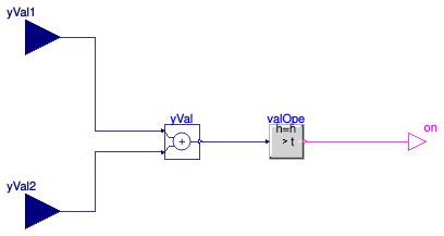
Controller for enabling the ETS heat exchanger
Information
Controller for enabling the ETS heat exchanger pump.
The controller outputs true to enable the heat exchanger pump if
no tank is requesting to be charged, and
if at least one of the two isolation valves is sufficiently open.
Otherwise, the controller outputs false.
Extends from Modelica.Blocks.Icons.Block (Basic graphical layout of input/output block).
Connectors
Modelica definition
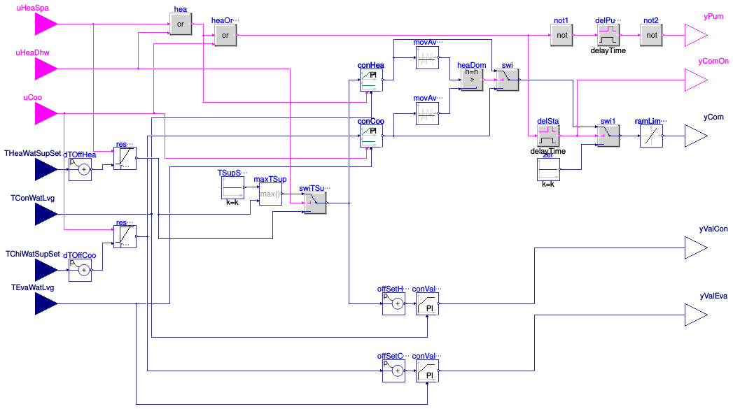
Modular heat pump controller
Information
This is a controller for the heat pump system, which includes controls
for the valves that ensure a minimum condenser outlet and a maximum
evaporator outlet temperature.
The system is enabled if any of the input control signals uHeaSpa,
uHeaDhw,
or uCoo is true.
When enabled, the following control is used:
-
Two proportional controllers compute the required compressor speed to track
the heating or cooling set point.
-
Moving averages of these compressor speed signals determine whether the heating or the
cooling compressor speed should be taken. The larger of the moving averages determines
whether the heat pump is controlled to meet the heating or cooling demand.
-
The compressor speed is modulated between a minimum and maximum speed based on
the heating or cooling control signal.
A rate limiter is used to avoid step changes in demanded compressor speed.
-
The condenser and evaporator mixing valves are modulated with a proportional controller
to maintain a minimum (resp. maximum) outlet temperature from the heat pump.
Parameters
| Type | Name | Default | Description |
|---|
| Real | PLRMin | | Minimum part load ratio |
| Real | kHea | 2 | Gain of controller for compressor during heating operation |
| Real | kCoo | 2 | Gain of controller for compressor during cooling |
| Real | THeaWatSupSetMin | | Minimum value of heating water supply temperature set point [K] |
| Real | TChiWatSupSetMax | | Maximum value of chilled water supply temperature set point [K] |
| TemperatureDifference | dTOffSetHea | | Temperature to be added to the set point in order to be slightly above what the heating load requires [K] |
| TemperatureDifference | dTOffSetCoo | | Temperature to be added to the set point in order to be slightly below what the cooling load requires [K] |
Connectors
| Type | Name | Description |
|---|
| input BooleanInput | uHeaSpa | True if space heating is required from tank |
| input BooleanInput | uHeaDhw | True if domestic hot water heating is required from tank |
| input BooleanInput | uCoo | True if cooling is required from tank |
| input RealInput | THeaWatSupSet | Set point temperature for heating water [K] |
| input RealInput | TConWatLvg | Condenser water leaving temperature [K] |
| input RealInput | TEvaWatLvg | Evaporator water leaving temperature [K] |
| input RealInput | TChiWatSupSet | Set point temperature for chilled water [K] |
| output RealOutput | yValCon | Condenser mixing valve control signal |
| output RealOutput | yValEva | Evaporator mixing valve control signal |
| output BooleanOutput | yPum | Primary pump enable signal |
| output BooleanOutput | yComOn | Outputs true if the compressor is on |
| output RealOutput | yCom | Compressor speed control signal |
Modelica definition
model HeatPumpModular
parameter Real PLRMin(min=0) ;
parameter Real kHea=2
;
parameter Real kCoo=2 ;
parameter Real THeaWatSupSetMin(
final quantity="ThermodynamicTemperature",
final unit="K",
displayUnit="degC")
;
parameter Real TChiWatSupSetMax(
final quantity="ThermodynamicTemperature",
final unit="K",
displayUnit="degC")
;
parameter Modelica.Units.SI.TemperatureDifference dTOffSetHea(
min=0.5,
displayUnit="K")
;
parameter Modelica.Units.SI.TemperatureDifference dTOffSetCoo(
max=-0.5,
displayUnit="K")
;
Buildings.Controls.OBC.CDL.Interfaces.BooleanInput uHeaSpa
;
Buildings.Controls.OBC.CDL.Interfaces.BooleanInput uHeaDhw
;
Buildings.Controls.OBC.CDL.Interfaces.BooleanInput uCoo
;
Buildings.Controls.OBC.CDL.Interfaces.RealInput THeaWatSupSet(
final unit="K",
displayUnit="degC") ;
Buildings.Controls.OBC.CDL.Interfaces.RealInput TConWatLvg(
final unit="K",
displayUnit="degC") ;
Buildings.Controls.OBC.CDL.Interfaces.RealInput TEvaWatLvg(
final unit="K",
displayUnit="degC") ;
Buildings.Controls.OBC.CDL.Interfaces.RealInput TChiWatSupSet(
final unit="K",
displayUnit="degC") ;
Buildings.Controls.OBC.CDL.Interfaces.RealOutput yValCon
;
Buildings.Controls.OBC.CDL.Interfaces.RealOutput yValEva
;
Buildings.Controls.OBC.CDL.Interfaces.BooleanOutput yPum
;
Buildings.Controls.OBC.CDL.Interfaces.BooleanOutput yComOn
;
Buildings.Controls.OBC.CDL.Logical.Or heaOrCoo ;
Buildings.Controls.OBC.CDL.Reals.PID conValHea(
final controllerType=Buildings.Controls.OBC.CDL.Types.SimpleController.P,
final yMax=1,
final yMin=0,
k=kHea,
Ti=60,
final reverseActing=false,
u_s(
final unit="K", displayUnit="degC"),
u_m(
final unit="K", displayUnit="degC"))
;
Buildings.Controls.OBC.CDL.Reals.PID conValCoo(
final controllerType=Buildings.Controls.OBC.CDL.Types.SimpleController.P,
final yMax=1,
final yMin=0,
k=kCoo,
Ti=60,
final reverseActing=true,
u_s(
final unit="K", displayUnit="degC"),
u_m(
final unit="K", displayUnit="degC")) ;
Buildings.Controls.OBC.CDL.Interfaces.RealOutput yCom
;
Buildings.Controls.OBC.Utilities.PIDWithEnable conCoo(
final controllerType=Buildings.Controls.OBC.CDL.Types.SimpleController.P,
final yMax=1,
final yMin=PLRMin,
final k=kCoo,
y_reset=PLRMin,
Ti(displayUnit="s") = 300,
final reverseActing=false,
final y_neutral=0,
u_s(
final unit="K", displayUnit="degC"),
u_m(
final unit="K", displayUnit="degC"))
;
Buildings.Controls.OBC.Utilities.PIDWithEnable conHea(
final controllerType=Buildings.Controls.OBC.CDL.Types.SimpleController.P,
final yMax=1,
final yMin=PLRMin,
final k=kHea,
y_reset=PLRMin,
Ti(displayUnit="s") = 300,
final reverseActing=true,
final y_neutral=0,
u_s(
final unit="K", displayUnit="degC"),
u_m(
final unit="K", displayUnit="degC"))
;
Buildings.Controls.OBC.CDL.Reals.Switch swi
;
Buildings.Controls.OBC.CDL.Reals.LimitSlewRate ramLimCom(
raisingSlewRate=1/(15*60),
fallingSlewRate=-1/30,
Td=1) ;
Buildings.Controls.OBC.CDL.Logical.Or hea ;
Buildings.Controls.OBC.CDL.Reals.MovingAverage movAveHea(delta=600)
;
Buildings.Controls.OBC.CDL.Reals.MovingAverage movAveCoo(delta=600)
;
Buildings.Controls.OBC.CDL.Reals.Greater heaDom(h=0.001)
;
Buildings.Controls.OBC.CDL.Reals.Switch swi1
;
Buildings.Controls.OBC.CDL.Reals.Sources.Constant zer(
final k=0)
;
Buildings.Controls.OBC.CDL.Reals.Sources.Constant TSupSetDhw(
y(
final unit="K",
displayUnit="degC"),
final k(
final unit="K",
displayUnit="degC") = 323.15)
;
Buildings.Controls.OBC.CDL.Reals.Switch swiTSupSetHea(
u1(
final unit="K", displayUnit="degC"),
u3(
final unit="K", displayUnit="degC"),
y(
final unit="K", displayUnit="degC"))
;
Buildings.Controls.OBC.CDL.Reals.AddParameter offSetHea(
p(
final unit="K")=-1/kHea*2,
u(
final unit="K", displayUnit="degC"),
y(
final unit="K", displayUnit="degC"))
;
Buildings.Controls.OBC.CDL.Reals.AddParameter offSetCoo(
p(
final unit="K")=+1/kCoo*2,
u(
final unit="K", displayUnit="degC"),
y(
final unit="K", displayUnit="degC"))
;
Buildings.DHC.ETS.Combined.Controls.Reset resTHeaSup(
final TWatSupSetMinMax=THeaWatSupSetMin)
;
Buildings.DHC.ETS.Combined.Controls.Reset resTCooSup(
final TWatSupSetMinMax=TChiWatSupSetMax)
;
Buildings.Controls.OBC.CDL.Reals.Max maxTSup(
u1(
final unit="K", displayUnit="degC"),
u2(
final unit="K", displayUnit="degC"),
y(
final unit="K", displayUnit="degC"))
;
Buildings.Controls.OBC.CDL.Logical.TrueDelay delSta(delayTime=30)
;
Buildings.Controls.OBC.CDL.Logical.TrueDelay delPumOff(delayTime=30)
;
Buildings.Controls.OBC.CDL.Logical.Not not1;
Buildings.Controls.OBC.CDL.Logical.Not not2;
Buildings.Controls.OBC.CDL.Reals.AddParameter dTOffHea(
p=dTOffSetHea,
u(
final unit="K", displayUnit="degC"),
y(
final unit="K", displayUnit="degC"))
;
Buildings.Controls.OBC.CDL.Reals.AddParameter dTOffCoo(
p=dTOffSetCoo,
u(
final unit="K", displayUnit="degC"),
y(
final unit="K", displayUnit="degC"))
;
equation
connect(uCoo,heaOrCoo.u2);
connect(TEvaWatLvg,conCoo. u_m);
connect(TConWatLvg, conHea.u_m);
connect(conCoo.uEna, uCoo);
connect(hea.u1, uHeaSpa);
connect(hea.u2, uHeaDhw);
connect(hea.y, heaOrCoo.u1);
connect(hea.y, conHea.uEna);
connect(movAveHea.u, conHea.y);
connect(conCoo.y, movAveCoo.u);
connect(movAveHea.y, heaDom.u1);
connect(movAveCoo.y, heaDom.u2);
connect(heaDom.y, swi.u2);
connect(conHea.y, swi.u1);
connect(conCoo.y, swi.u3);
connect(zer.y, swi1.u3);
connect(swiTSupSetHea.u2, uHeaDhw);
connect(conValHea.u_s, offSetHea.y);
connect(TConWatLvg, conValHea.u_m);
connect(conValCoo.u_s, offSetCoo.y);
connect(conValHea.y, yValCon);
connect(conValCoo.y, yValEva);
connect(resTHeaSup.TWatSupSet, swiTSupSetHea.u3);
connect(resTCooSup.TWatSupSet, conCoo.u_s);
connect(resTCooSup.u, uCoo);
connect(resTHeaSup.u, uHeaSpa);
connect(maxTSup.y, swiTSupSetHea.u1);
connect(TSupSetDhw.y, maxTSup.u1);
connect(resTHeaSup.TWatSupSet, maxTSup.u2);
connect(TEvaWatLvg, conValCoo.u_m);
connect(resTCooSup.TWatSupSet, offSetCoo.u);
connect(delSta.y, swi1.u2);
connect(delSta.u, heaOrCoo.y);
connect(swi.y, swi1.u1);
connect(swi1.y, ramLimCom.u);
connect(ramLimCom.y,yCom);
connect(heaOrCoo.y, not1.u);
connect(not1.y, delPumOff.u);
connect(delPumOff.y, not2.u);
connect(not2.y, yPum);
connect(yComOn, delSta.y);
connect(offSetHea.u, swiTSupSetHea.y);
connect(swiTSupSetHea.y, conHea.u_s);
connect(TChiWatSupSet, dTOffCoo.u);
connect(dTOffCoo.y, resTCooSup.TWatSupPreSet);
connect(THeaWatSupSet, dTOffHea.u);
connect(dTOffHea.y, resTHeaSup.TWatSupPreSet);
end HeatPumpModular;
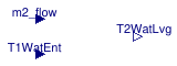
Block that predicts heat exchanger leaving water temperature
Information
This block computes the predicted heat exchanger leaving water temperature
as used in
Buildings.DHC.ETS.Combined.Controls.WatersideEconomizer.
The predicted heat exchanger approach is computed as
dTApp = dTApp_nominal * m2_flow / m2_flow_nominal,
which gives the predicted heat exchanger leaving water temperature as
T2WatLvg = T1WatEnt + dTApp.
Parameters
| Type | Name | Default | Description |
|---|
| Nominal condition |
| Real | dTApp_nominal | | Heat exchanger approach [K] |
| Real | m2_flow_nominal | | Heat exchanger secondary mass flow rate [kg/s] |
Connectors
| Type | Name | Description |
|---|
| input RealInput | m2_flow | Heat exchanger secondary mass flow rate [kg/s] |
| input RealInput | T1WatEnt | Heat exchanger primary water entering temperature [K] |
| output RealOutput | T2WatLvg | Heat exchanger secondary water leaving temperature [K] |
Modelica definition
model PredictLeavingTemperature
parameter Real dTApp_nominal(
final quantity="TemperatureDifference",
final unit="K")
;
parameter Real m2_flow_nominal(
final quantity="MassFlowRate",
final unit="kg/s")
;
Buildings.Controls.OBC.CDL.Interfaces.RealInput m2_flow(
final unit="kg/s")
;
Buildings.Controls.OBC.CDL.Interfaces.RealInput T1WatEnt(
final unit="K",
displayUnit="degC")
;
Buildings.Controls.OBC.CDL.Interfaces.RealOutput T2WatLvg(
final unit="K",
displayUnit="degC")
;
Buildings.Controls.OBC.CDL.Reals.Divide div1 ;
Buildings.Controls.OBC.CDL.Reals.Sources.Constant con(
final k=m2_flow_nominal)
;
Buildings.Controls.OBC.CDL.Reals.Min min1 ;
Buildings.Controls.OBC.CDL.Reals.Abs abs1 ;
Buildings.Controls.OBC.CDL.Reals.Sources.Constant con1(
final k=1) ;
Buildings.Controls.OBC.CDL.Reals.Sources.Constant con2(
final k=dTApp_nominal)
;
Buildings.Controls.OBC.CDL.Reals.Multiply mul ;
Buildings.Controls.OBC.CDL.Reals.Add add2
;
equation
connect(m2_flow, div1.u1);
connect(con.y, div1.u2);
connect(div1.y, abs1.u);
connect(abs1.y, min1.u1);
connect(con1.y, min1.u2);
connect(con2.y, mul.u2);
connect(min1.y, mul.u1);
connect(mul.y, add2.u1);
connect(T1WatEnt, add2.u2);
connect(add2.y, T2WatLvg);
end PredictLeavingTemperature;
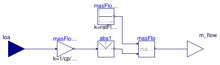
Ideal control of condenser or evaporator variable flow rate
Information
This block implements an ideal control of the evaporator (or condenser) water
mass flow rate.
The control intent aims to maintain a constant water temperature difference
dT_nominal across the heat exchanger, within the limit of a
minimum mass flow rate ratio ratFloMin.
For computational performance and to avoid the use of a PI controller,
the required mass flow rate is computed based on a signal representative of
the load.
Parameters
| Type | Name | Default | Description |
|---|
| Real | Q_flow_nominal | | Heat flow rate at nominal conditions (>0 for condenser) [W] |
| Real | dT_nominal | | DeltaT at nominal conditions (>0 for condenser) [K] |
| Real | ratFloMin | 0.3 | Minimum mass flow rate (ratio to nominal) [1] |
Connectors
| Type | Name | Description |
|---|
| input RealInput | loa | Signal approximating the load on condenser or evaporator [W] |
| output RealOutput | m_flow | Mass flow rate [kg/s] |
Modelica definition
block PrimaryVariableFlow
constant Real cp(
final quantity="SpecificHeatCapacity",
final unit="J/(kg.K)")=Buildings.Utilities.Psychrometrics.Constants.cpWatLiq
;
parameter Real Q_flow_nominal(
final quantity="HeatFlowRate",
final unit="W")
;
parameter Real dT_nominal(
final quantity="TemperatureDifference",
final unit="K",
min=
if Q_flow_nominal > 0
then Buildings.Controls.OBC.CDL.Constants.eps
else -100,
max=
if Q_flow_nominal < 0
then -Buildings.Controls.OBC.CDL.Constants.eps
else 100)
;
parameter Real ratFloMin(
final unit="1",
final min=0,
final max=1)=0.3
;
final parameter Real m_flow_nominal(
final quantity="MassFlowRate",
final unit="kg/s",
final min=0)=
Q_flow_nominal/cp/dT_nominal
;
Buildings.Controls.OBC.CDL.Interfaces.RealInput loa(
final unit="W")
;
Buildings.Controls.OBC.CDL.Interfaces.RealOutput m_flow(
final unit="kg/s")
;
Buildings.Controls.OBC.CDL.Reals.Sources.Constant masFloMin(
final k=ratFloMin*m_flow_nominal)
;
Buildings.Controls.OBC.CDL.Reals.MultiplyByParameter masFlo_dT(
final k=1/cp/dT_nominal)
;
Buildings.Controls.OBC.CDL.Reals.Max masFlo ;
Buildings.Controls.OBC.CDL.Reals.Abs abs1 ;
equation
connect(loa, masFlo_dT.u);
connect(masFloMin.y, masFlo.u1);
connect(masFlo.y, m_flow);
connect(masFlo_dT.y, abs1.u);
connect(abs1.y, masFlo.u2);
end PrimaryVariableFlow;
Supervisory supply temperature reset
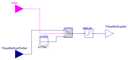
Information
This block implements the supervisory reset of the heating water
supply temperature.
The heating water supply temperature is reset down whenever the
heating demand signal yielded by the building automation system
is false.
This enables operating the chiller at a reduced lift whenever
there is no requirement on the water temperature supplied to the
building system.
Note that the chilled water supply temperature is not reset
for the sake of simplicity. It would indeed require a more
involved algorithm preventing the reset in case it limits
the cold rejection capacity considering the actual
district water temperature.
Parameters
| Type | Name | Default | Description |
|---|
| Real | TWatSupSetMinMax | | Minimum of maximum value of heating or cooling water supply temperature set point [K] |
Connectors
| Type | Name | Description |
|---|
| input BooleanInput | u | Heating or cooling enable signal |
| input RealInput | TWatSupPreSet | Heating or cooling water supply temperature set point [K] |
| output RealOutput | TWatSupSet | Heating or cooling water supply temperature set point after reset [K] |
Modelica definition
Controller for flow switch box
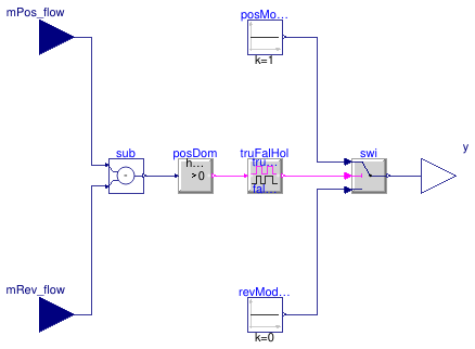
Information
This block implements a control logic preventing flow reversal in the
service line, for instance with the hydronic configuration of
Buildings.DHC.ETS.Combined.HeatPumpHeatExchanger.
The block requires two input signals representing the mass flow rate contributing
to a positive flow direction mPos_flow and the mass flow contributing
to a reverse flow direction mRev_flow.
The output signal y switches to maintain mPos_flow ≥ mRev_flow
with a temporization avoiding short cycling.
Due to the temporization, the mass flow rate may transiently change direction as
illustrated in
Buildings.DHC.ETS.Combined.Subsystems.Validation.SwitchBox.
Parameters
| Type | Name | Default | Description |
|---|
| Real | trueHoldDuration | | true hold duration [s] |
| Real | falseHoldDuration | trueHoldDuration | false hold duration [s] |
| Nominal condition |
| Real | m_flow_nominal | | Nominal mass flow rate, used for scaling to avoid chattering [kg/s] |
Connectors
| Type | Name | Description |
|---|
| input RealInput | mPos_flow | Service water mass flow rate in positive direction [kg/s] |
| input RealInput | mRev_flow | Service water mass flow rate in reverse direction [kg/s] |
| output RealOutput | y | Control output signal [1] |
Modelica definition
block SwitchBox
parameter Real m_flow_nominal(
final quantity="MassFlowRate",
final unit="kg/s")
;
parameter Real trueHoldDuration(
final quantity="Time",
final unit="s")
;
parameter Real falseHoldDuration(
final quantity="Time",
final unit="s") = trueHoldDuration
;
Buildings.Controls.OBC.CDL.Interfaces.RealInput mPos_flow(
final unit="kg/s")
;
Buildings.Controls.OBC.CDL.Interfaces.RealInput mRev_flow(
final unit="kg/s")
;
Buildings.Controls.OBC.CDL.Interfaces.RealOutput y(
final unit="1")
;
Buildings.Controls.OBC.CDL.Reals.GreaterThreshold posDom(
final h=0.001*m_flow_nominal)
;
Buildings.Controls.OBC.CDL.Reals.Switch swi
;
Buildings.Controls.OBC.CDL.Reals.Sources.Constant posModOn(
final k=1)
;
Buildings.Controls.OBC.CDL.Logical.TrueFalseHold truFalHol(
final trueHoldDuration=trueHoldDuration,
final falseHoldDuration=falseHoldDuration)
;
Buildings.Controls.OBC.CDL.Reals.Sources.Constant revModOn(
final k=0)
;
Buildings.Controls.OBC.CDL.Reals.Subtract sub
;
Buildings.Controls.OBC.CDL.Reals.MovingAverage movAve(
final delta=trueHoldDuration/10)
;
equation
connect(posModOn.y, swi.u1);
connect(swi.y, y);
connect(posDom.y, truFalHol.u);
connect(truFalHol.y, swi.u2);
connect(revModOn.y, swi.u3);
connect(mPos_flow, sub.u1);
connect(mRev_flow, sub.u2);
connect(posDom.u, movAve.y);
connect(movAve.u, sub.y);
end SwitchBox;
Controller to enable or disable storage tank charging
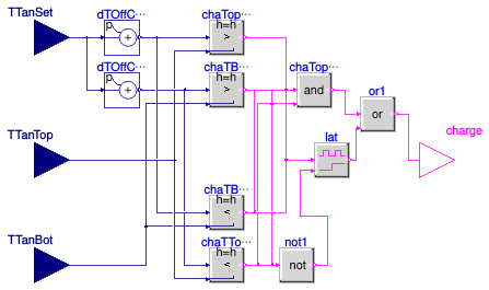
Information
Adapted fromBuildings.DHC.Loads.HotWater.BaseClasses.TankChargingController.
-
The hysteresis parameters are exposed.
-
Added a routing block so that it could be applied to both
hot and cold tanks, i.e. either the top or bottom of the tank
could be the supply side or the return side.
Parameters
| Type | Name | Default | Description |
|---|
| TemperatureDifference | dTOffSet | if isHotWat then +1 else -1 | Offset for set point to have a slightly higher (or lower) temperature than the required supply from the load [K] |
| Boolean | isHotWat | | True if the tank supplies hot water, False for chilled water |
Connectors
| Type | Name | Description |
|---|
| input RealInput | TTanTop | Measured temperature at top of tank [K] |
| input RealInput | TTanSet | Tank temperature set point, top for hot tank and bottom for cold tank [K] |
| output BooleanOutput | charge | Outputs true if tank should be charged |
| input RealInput | TTanBot | Measured temperature at bottom of tank [K] |
Modelica definition
block TankChargingController
parameter Modelica.Units.SI.TemperatureDifference dTOffSet=
if isHotWat
then +1
else -1
;
parameter Boolean isHotWat
;
Buildings.Controls.OBC.CDL.Interfaces.RealInput TTanTop(
final unit="K",
displayUnit="degC") ;
Modelica.Blocks.Interfaces.RealInput TTanSet(
final unit="K",
displayUnit="degC")
;
Buildings.Controls.OBC.CDL.Interfaces.BooleanOutput charge
;
Buildings.Controls.OBC.CDL.Interfaces.RealInput TTanBot(
final unit="K", displayUnit=
"degC") ;
Buildings.Controls.OBC.CDL.Logical.Latch lat ;
Buildings.Controls.OBC.CDL.Logical.Not not1 ;
Buildings.Controls.OBC.CDL.Logical.And chaTopBot
;
Buildings.Controls.OBC.CDL.Logical.Or or1
;
Buildings.Controls.OBC.CDL.Reals.AddParameter dTOffChaOn(
final p=dTOffSet,
u(
final unit="K", displayUnit="degC"),
y(
final unit="K", displayUnit="degC")) ;
Buildings.Controls.OBC.CDL.Reals.AddParameter dTOffChaOff(
final p=2*dTOffSet,
u(
final unit="K", displayUnit="degC"),
y(
final unit="K", displayUnit="degC")) ;
Buildings.Controls.OBC.CDL.Reals.Greater chaTopHea(
h=dTOffSet/2,
u1(
final unit="K", displayUnit="degC"),
u2(
final unit="K", displayUnit="degC"))
if isHotWat
;
Buildings.Controls.OBC.CDL.Reals.Greater chaTBotHea(
h=dTOffSet/2,
u1(
final unit="K", displayUnit="degC"),
u2(
final unit="K", displayUnit="degC"))
if isHotWat
;
Buildings.Controls.OBC.CDL.Reals.Less chaTBotCoo(
h=-dTOffSet/2,
u1(
final unit="K", displayUnit="degC"),
u2(
final unit="K", displayUnit="degC"))
if not isHotWat
;
Buildings.Controls.OBC.CDL.Reals.Less chaTTopCoo(
h=-dTOffSet/2,
u1(
final unit="K", displayUnit="degC"),
u2(
final unit="K", displayUnit="degC"))
if not isHotWat
;
equation
connect(not1.y, lat.clr);
connect(or1.y, charge);
connect(lat.y, or1.u2);
connect(or1.u1, chaTopBot.y);
connect(TTanSet, dTOffChaOn.u);
connect(chaTopHea.u1, dTOffChaOn.y);
connect(dTOffChaOff.y, chaTBotHea.u1);
connect(TTanTop, chaTopHea.u2);
connect(chaTopHea.y, chaTopBot.u1);
connect(chaTBotHea.y, chaTopBot.u2);
connect(lat.u, chaTopHea.y);
connect(not1.u, chaTBotHea.y);
connect(chaTTopCoo.u1, dTOffChaOff.y);
connect(chaTBotCoo.u1, dTOffChaOn.y);
connect(chaTBotCoo.u2, TTanBot);
connect(chaTTopCoo.u2, TTanTop);
connect(chaTBotCoo.y, chaTopBot.u1);
connect(chaTTopCoo.y, chaTopBot.u2);
connect(not1.u, chaTTopCoo.y);
connect(chaTBotCoo.y, lat.u);
connect(dTOffChaOff.u, TTanSet);
connect(chaTBotHea.u2, TTanBot);
end TankChargingController;
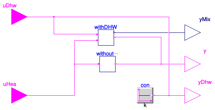
Information
This block routes the connectors on the evaporator side of the ETS
depending on whether DHW integration is present.
It also sends a signal to open the diversion valve when there is HHW or DHW
load present. If the DHW integration is present, this block also controls
the mixing valve which directs the condenser water to the HHW or DHW tanks,
sometimes both.
When DHW integration is present:
| Input: load present |
Output |
| DHW |
HHW |
yMix |
yDiv |
TTop |
TSet |
| T |
T |
0.5 |
1 |
The one with higher TSet |
Max of two |
| T |
F |
0 |
1 |
DHW |
DHW |
| F |
T |
1 |
1 |
HHW |
HHW |
| F |
F |
1 |
0 |
HHW |
HHW |
Extends from Modelica.Blocks.Icons.Block (Basic graphical layout of input/output block).
Parameters
| Type | Name | Default | Description |
|---|
| Boolean | have_hotWat | true | True if there is integrated DHW |
Connectors
| Type | Name | Description |
|---|
| input BooleanInput | uDhw | Charge request from the domestic hot water tank |
| input BooleanInput | uHea | Charge request from the heating hot water tank |
| output BooleanOutput | y | Enable command |
| output RealOutput | yMix | Mixing valve control signal [1] |
| output BooleanOutput | yDhw | Charge command from DHW tank, or false if no tank present |
Modelica definition
Waterside economizer controller
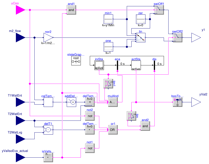
Information
This block implements the control logic for the waterside economizer.
The system is enabled if
-
it has been disabled for more than 20 minutes, and
-
the "cooling enabled" input signal is
true, and
-
the evaporator isolation valve is closed (i.e., the system is not in cold
rejection mode), and
-
the predicted leaving water temperature is lower than the entering water
temperature minus
dTEna.
The system is disabled if
-
it has been enabled for more than 20 minutes, and
-
the "cooling enabled" input signal is
false, or
-
the evaporator isolation valve is open, or
-
the leaving water temperature is higher than the entering water
temperature minus
dTDis.
When the system is enabled
-
the primary side is controlled so that the primary flow rate
varies linearly with the secondary flow rate, and
-
the bypass valve on the secondary side is fully closed.
When the system is disabled
-
if the "cooling enabled" input signal is
true and
the evaporator isolation valve is closed,
the primary pump (resp. valve) is operated at its minimum speed
(resp. opening), otherwise it is switched off (resp. fully closed):
this is needed to yield a representative measurement of the
service water entering temperature, and
-
the bypass valve on the secondary side is fully open.
Parameters
| Type | Name | Default | Description |
|---|
| Nominal condition |
| Real | m2_flow_nominal | | Heat exchanger secondary mass flow rate [kg/s] |
| Real | T_a1_nominal | | Nominal water inlet temperature on district side [K] |
| Real | T_b2_nominal | | Nominal water outlet temperature on building side [K] |
| Controls |
| Real | y1Min | 0.05 | Minimum pump flow rate or valve opening for temperature measurement (fractional) [1] |
| Real | dTEna | 1 | Minimum delta-T above predicted heat exchanger leaving water temperature to enable WSE [K] |
| Real | dTDis | 0.5 | Minimum delta-T across heat exchanger before disabling WSE [K] |
Connectors
| Type | Name | Description |
|---|
| input BooleanInput | uCoo | Cooling enable signal |
| input RealInput | m2_flow | Heat exchanger secondary mass flow rate [kg/s] |
| input RealInput | T1WatEnt | Heat exchanger primary water entering temperature [K] |
| input RealInput | T2WatEnt | Heat exchanger secondary water entering temperature [K] |
| input RealInput | T2WatLvg | Heat exchanger secondary water leaving temperature [K] |
| input RealInput | yValIsoEva_actual | Return position of evaporator to ambient loop isolation valve [1] |
| output RealOutput | y1 | Primary control signal (pump or valve) [1] |
| output RealOutput | yVal2 | Secondary valve control signal [1] |
Modelica definition
model WatersideEconomizer
parameter Real m2_flow_nominal(
final quantity="MassFlowRate",
final unit="kg/s")
;
parameter Real T_a1_nominal(
final unit="K",
displayUnit="degC",
final quantity="ThermodynamicTemperature")
;
parameter Real T_b2_nominal(
final unit="K",
displayUnit="degC",
final quantity="ThermodynamicTemperature")
;
parameter Real y1Min(
final unit="1")=0.05
;
parameter Real dTEna(
final quantity="TemperatureDifference",
final unit="K")=1
;
parameter Real dTDis(
final quantity="TemperatureDifference",
final unit="K")=0.5
;
Buildings.Controls.OBC.CDL.Interfaces.BooleanInput uCoo
;
Buildings.Controls.OBC.CDL.Interfaces.RealInput m2_flow(
final unit="kg/s")
;
Buildings.Controls.OBC.CDL.Interfaces.RealInput T1WatEnt(
final unit="K",
displayUnit="degC")
;
Buildings.Controls.OBC.CDL.Interfaces.RealInput T2WatEnt(
final unit="K",
displayUnit="degC")
;
Buildings.Controls.OBC.CDL.Interfaces.RealInput T2WatLvg(
final unit="K",
displayUnit="degC")
;
Buildings.Controls.OBC.CDL.Interfaces.RealInput yValIsoEva_actual(
final unit="1")
;
Buildings.Controls.OBC.CDL.Interfaces.RealOutput y1(
final unit="1")
;
Buildings.Controls.OBC.CDL.Interfaces.RealOutput yVal2(
final unit="1")
;
Buildings.Controls.OBC.CDL.Reals.AddParameter addDelTem(
final p=dTEna)
;
Modelica.StateGraph.InitialStepWithSignal iniSta(nIn=1, nOut=1)
;
Modelica.StateGraph.TransitionWithSignal ena ;
Modelica.StateGraph.StepWithSignal actSta(nIn=1, nOut=1)
;
Modelica.StateGraph.TransitionWithSignal dis
;
Buildings.Controls.OBC.CDL.Reals.Subtract delT1
;
Buildings.Controls.OBC.CDL.Reals.LessThreshold delTemDis(
final t = dTDis,
final h = 0.05)
;
Buildings.DHC.ETS.Combined.Controls.PredictLeavingTemperature calTemLvg(
final dTApp_nominal=
abs(T_a1_nominal - T_b2_nominal),
final m2_flow_nominal=m2_flow_nominal)
;
Buildings.Controls.OBC.CDL.Reals.Less delTemDis1(
final h = 0.05)
;
Buildings.Controls.OBC.CDL.Conversions.BooleanToReal booToRea(
final realTrue=1,
final realFalse=0)
;
inner Modelica.StateGraph.StateGraphRoot stateGraphRoot ;
Buildings.Controls.OBC.CDL.Reals.Sources.Constant min1(
final k=y1Min)
;
Buildings.Controls.OBC.CDL.Reals.Line lin
;
Buildings.Controls.OBC.CDL.Reals.Switch swiOff1
;
Buildings.Controls.OBC.CDL.Reals.Sources.Constant zer(
final k=0) ;
Buildings.Controls.OBC.CDL.Logical.MultiAnd mulAnd(nin=4)
;
Buildings.Controls.OBC.CDL.Logical.MultiOr or1(nin=3)
;
Buildings.Controls.OBC.CDL.Logical.Not not2 ;
Buildings.Controls.OBC.CDL.Logical.Timer tim(t=1200)
;
Buildings.Controls.OBC.CDL.Logical.Timer tim1(t=1200)
;
Buildings.Controls.OBC.CDL.Logical.And and2
;
Buildings.Controls.OBC.CDL.Reals.LessThreshold isValIsoEvaClo(
final t=0.01,
h=0.005)
;
Buildings.Controls.OBC.CDL.Logical.Not not1 ;
Buildings.Controls.OBC.CDL.Logical.And and1
;
Buildings.Controls.OBC.CDL.Reals.MultiplyByParameter nor2(
final k=1/m2_flow_nominal) ;
Buildings.Controls.OBC.CDL.Reals.Switch swiOff2
;
Buildings.Controls.OBC.CDL.Reals.Sources.Constant one(
final k=1) ;
equation
connect(T2WatEnt, delT1.u1);
connect(T2WatLvg, delT1.u2);
connect(delT1.y, delTemDis.u);
connect(T1WatEnt, calTemLvg.T1WatEnt);
connect(calTemLvg.T2WatLvg, addDelTem.u);
connect(addDelTem.y, delTemDis1.u1);
connect(T2WatEnt, delTemDis1.u2);
connect(iniSta.outPort[1], ena.inPort);
connect(ena.outPort, actSta.inPort[1]);
connect(actSta.outPort[1], dis.inPort);
connect(dis.outPort, iniSta.inPort[1]);
connect(booToRea.y, yVal2);
connect(zer.y, swiOff1.u3);
connect(mulAnd.y, ena.condition);
connect(uCoo, not2.u);
connect(actSta.active, booToRea.u);
connect(delTemDis1.y, mulAnd.u[1]);
connect(iniSta.active, tim1.u);
connect(tim1.passed, mulAnd.u[2]);
connect(uCoo, mulAnd.u[3]);
connect(actSta.active, tim.u);
connect(tim.passed, and2.u1);
connect(or1.y, and2.u2);
connect(and2.y, dis.condition);
connect(m2_flow, calTemLvg.m2_flow);
connect(yValIsoEva_actual,isValIsoEvaClo.u);
connect(isValIsoEvaClo.y, mulAnd.u[4]);
connect(isValIsoEvaClo.y, not1.u);
connect(delTemDis.y, or1.u[1]);
connect(not2.y, or1.u[2]);
connect(not1.y, or1.u[3]);
connect(uCoo, and1.u1);
connect(and1.y, swiOff1.u2);
connect(isValIsoEvaClo.y, and1.u2);
connect(m2_flow, nor2.u);
connect(min1.y, swiOff1.u1);
connect(swiOff2.y, y1);
connect(swiOff1.y, swiOff2.u1);
connect(iniSta.active, swiOff2.u2);
connect(lin.y, swiOff2.u3);
connect(nor2.y, lin.u);
connect(one.y, lin.x2);
connect(one.y, lin.f2);
connect(zer.y, lin.x1);
connect(min1.y, lin.f1);
end WatersideEconomizer;

Information
Extends from Modelica.Blocks.Icons.Block (Basic graphical layout of input/output block).
Connectors
| Type | Name | Description |
|---|
| input BooleanInput | uDhw | Charge request from the domestic hot water tank |
| input BooleanInput | uHea | Charge request from the heating hot water tank |
| output RealOutput | yMix | Mixing valve control signal [1] |
| output BooleanOutput | y | Enable command |
Modelica definition

Information
Extends from Modelica.Blocks.Icons.Block (Basic graphical layout of input/output block).
Connectors
Modelica definition
 Buildings.DHC.ETS.Combined.Controls.EtsHex
 Buildings.DHC.ETS.Combined.Controls.HeatPumpModular
 Buildings.DHC.ETS.Combined.Controls.PredictLeavingTemperature
 Buildings.DHC.ETS.Combined.Controls.PrimaryVariableFlow
 Buildings.DHC.ETS.Combined.Controls.Reset
 Buildings.DHC.ETS.Combined.Controls.SwitchBox
 Buildings.DHC.ETS.Combined.Controls.TankChargingController
 Buildings.DHC.ETS.Combined.Controls.TwoTankCoordination
 Buildings.DHC.ETS.Combined.Controls.WatersideEconomizer
 Buildings.DHC.ETS.Combined.Controls.TwoTankCoordination.WithDHW
 Buildings.DHC.ETS.Combined.Controls.TwoTankCoordination.WithoutDHW