Buildings.Applications.DataCenters.DXCooled.Controls

Package with controllers for DX-cooled data centers

Information

This package contains controllers for DX-cooled data centers.

Extends from Modelica.Icons.Package (Icon for standard packages).

Package Content

Name Description
Buildings.Applications.DataCenters.DXCooled.Controls.AirsideEconomizer AirsideEconomizer Controller for airside economizer
Buildings.Applications.DataCenters.DXCooled.Controls.Compressor Compressor Controller for compressor speed
Buildings.Applications.DataCenters.DXCooled.Controls.CoolingMode CoolingMode Controller for the DX cooling system with an airside economizer
Buildings.Applications.DataCenters.DXCooled.Controls.Validation Validation Collection of validation models

Buildings.Applications.DataCenters.DXCooled.Controls.AirsideEconomizer Buildings.Applications.DataCenters.DXCooled.Controls.AirsideEconomizer

Controller for airside economizer

Buildings.Applications.DataCenters.DXCooled.Controls.AirsideEconomizer

Information

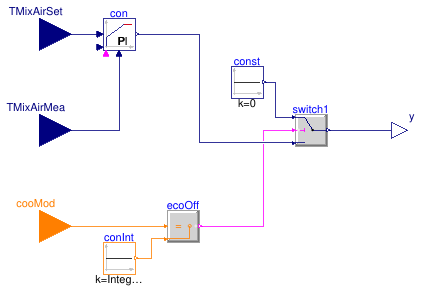
This model implements an airside economizer controller to modulate the outdoor air damper in order to maintain desired mixed air temperature. When the airside economizer is open, which means the system is in free cooling or partial mechanical cooling, the position of the OA damper is controlled by a PI controller to maintain a desired mixed air temperature; otherwise, the position of the OA damper is set as closed.

Parameters

TypeNameDefaultDescription
RealminOAFra Minimum outdoor air fraction [1]
Control
Realgai1Gain of controller
TimeTi50Integrator time [s]

Connectors

TypeNameDescription
input RealInputTMixAirSetMixed air setpoint temperature [K]
input RealInputTMixAirMeaMeasured mixed air temperature [K]
input IntegerInputcooModCooling mode of the cooling system
output RealOutputyConnector of Real output signal

Modelica definition

model AirsideEconomizer "Controller for airside economizer" parameter Real gai(min=Modelica.Constants.small) = 1 "Gain of controller"; parameter Modelica.Units.SI.Time Ti=50 "Integrator time"; parameter Real minOAFra(min=0,max=1, final unit="1") "Minimum outdoor air fraction"; Modelica.Blocks.Interfaces.RealInput TMixAirSet( final unit="K", final quantity="ThermodynamicTemperature", displayUnit="degC") "Mixed air setpoint temperature"; Modelica.Blocks.Interfaces.RealInput TMixAirMea( final unit="K", final quantity="ThermodynamicTemperature", displayUnit="degC") "Measured mixed air temperature"; Modelica.Blocks.Interfaces.IntegerInput cooMod "Cooling mode of the cooling system"; Modelica.Blocks.Interfaces.RealOutput y "Connector of Real output signal"; Buildings.Controls.Continuous.LimPID con( reverseActing=false, k=gai, yMin=minOAFra, final controllerType=Modelica.Blocks.Types.SimpleController.PI, Ti=Ti) "PID controller"; protected Buildings.Controls.OBC.CDL.Continuous.Sources.Constant const(final k=0) "Constant output signal with value 1"; Buildings.Controls.OBC.CDL.Integers.Sources.Constant conInt( final k=Integer(Types.CoolingModes.FullMechanical)) "Outputs signal for full mechanical cooling"; Buildings.Controls.OBC.CDL.Integers.Equal ecoOff "Determine if airside economizer is off"; Buildings.Controls.OBC.CDL.Continuous.Switch switch1 "Switch to select control output"; equation connect(TMixAirSet, con.u_s); connect(TMixAirMea, con.u_m); connect(switch1.y, y); connect(ecoOff.y, switch1.u2); connect(const.y, switch1.u1); connect(con.y, switch1.u3); connect(ecoOff.u2, conInt.y); connect(ecoOff.u1, cooMod); end AirsideEconomizer;

Buildings.Applications.DataCenters.DXCooled.Controls.Compressor Buildings.Applications.DataCenters.DXCooled.Controls.Compressor

Controller for compressor speed

Buildings.Applications.DataCenters.DXCooled.Controls.Compressor

Information

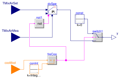
This model implements a PI controller to maintain the supply air temperature at its setpoint by adjusting the compressor's speed. When the free cooling is activated, the DX unit is deactivated by setting the speed signal as 0. In Partial Mechanical cooling and Full Mechanical cooling, the PI controller works to adjust the compressor's speed.

Parameters

TypeNameDefaultDescription
Realk0.5Gain of controller
TimeTi240Time constant of integrator block [s]
RealyMax1Upper limit of output
RealyMin0Lower limit of output
BooleanreverseActingfalseSet to true for throttling the water flow rate through a cooling coil controller

Connectors

TypeNameDescription
input IntegerInputcooModCooling mode of the cooling system
output RealOutputyCompressor speed [1]
input RealInputTMixAirSetMixed air setpoint temperature [K]
input RealInputTMixAirMeaMeasured mixed air temperature [K]

Modelica definition

model Compressor "Controller for compressor speed" parameter Real k=0.5 "Gain of controller"; parameter Modelica.Units.SI.Time Ti=240 "Time constant of integrator block"; parameter Real yMax=1 "Upper limit of output"; parameter Real yMin=0 "Lower limit of output"; parameter Boolean reverseActing=false "Set to true for throttling the water flow rate through a cooling coil controller"; Buildings.Controls.Continuous.LimPID dxSpe( Td=1, final controllerType=Modelica.Blocks.Types.SimpleController.PI, final k=k, final Ti=Ti, final yMax=yMax, final yMin=yMin, reverseActing=reverseActing, reset=Buildings.Types.Reset.Parameter, y_reset=yMin) "Controller for variable speed DX coil"; Modelica.Blocks.Interfaces.IntegerInput cooMod "Cooling mode of the cooling system"; Buildings.Controls.OBC.CDL.Interfaces.RealOutput y( min=0, max=1, final unit="1") "Compressor speed"; Modelica.Blocks.Interfaces.RealInput TMixAirSet( final unit="K", final quantity="ThermodynamicTemperature", displayUnit="degC") "Mixed air setpoint temperature"; Modelica.Blocks.Interfaces.RealInput TMixAirMea( final unit="K", final quantity="ThermodynamicTemperature", displayUnit="degC") "Measured mixed air temperature"; Buildings.Controls.OBC.CDL.Logical.Not not1 "Negation of signal to trigger the integrator reset"; protected Buildings.Controls.OBC.CDL.Integers.Sources.Constant conInt(final k=Integer( Buildings.Applications.DataCenters.Types.CoolingModes.FreeCooling)) "Outputs signal for full mechanical cooling"; Buildings.Controls.OBC.CDL.Integers.Equal freCoo "Determine if free cooling is on"; Buildings.Controls.OBC.CDL.Continuous.Switch switch1 "Switch to select control output"; Buildings.Controls.OBC.CDL.Continuous.Sources.Constant const(final k=0) "Constant output signal with value 1"; equation connect(cooMod, freCoo.u1); connect(conInt.y, freCoo.u2); connect(freCoo.y, switch1.u2); connect(const.y, switch1.u1); connect(dxSpe.y, switch1.u3); connect(switch1.y, y); connect(TMixAirSet, dxSpe.u_s); connect(TMixAirMea, dxSpe.u_m); connect(not1.y, dxSpe.trigger); connect(freCoo.y, not1.u); end Compressor;

Buildings.Applications.DataCenters.DXCooled.Controls.CoolingMode Buildings.Applications.DataCenters.DXCooled.Controls.CoolingMode

Controller for the DX cooling system with an airside economizer

Buildings.Applications.DataCenters.DXCooled.Controls.CoolingMode

Information

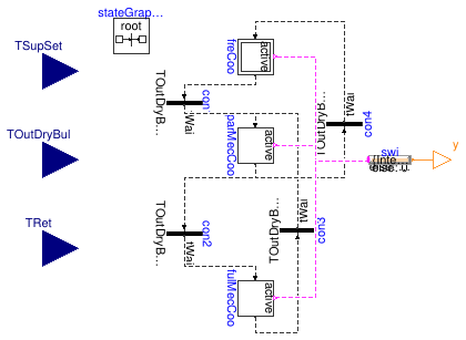
This model implements a cooling mode controller for an air-cooled direct expansion (DX) cooling system with an airside economizer. This controller is based on a simplified differential dry-bulb temperature control strategy, as described in ASHRAE G36.

There are three cooling modes for this system: free cooling (FC) mode, partially mechanical cooling (PMC) mode and fully mechanical cooling (FMC) mode. The detailed switching logic is shown in the following:

The airside economizer is enabled when:

The airside economizer is disabled when:

The DX coil is enabled when:

The DX coil is disabled when:

where Tswi is the switching temperature, subscript set means set point, out means outdoor air, ret means return air, and sup means supply air. A deadband δT can be added to the above logics to avoid frequent switching.

Parameters

TypeNameDefaultDescription
TimetWai Waiting time, set to avoid frequent switching [s]
TemperatureDifferencedT1.1Deadband [K]

Connectors

TypeNameDescription
input RealInputTOutDryBulDry-bulb temperature of outdoor air [K]
input RealInputTRetReturn air temperature [K]
input RealInputTSupSetSupply air temperature setpoint [K]
output IntegerOutputyCooling mode signal, integer value of Buildings.Applications.DataCenters.Examples.BaseClasses.Types.CoolingMode

Modelica definition

model CoolingMode "Controller for the DX cooling system with an airside economizer" parameter Modelica.Units.SI.Time tWai "Waiting time, set to avoid frequent switching"; parameter Modelica.Units.SI.TemperatureDifference dT(min=0.1) = 1.1 "Deadband"; Modelica.Blocks.Interfaces.RealInput TOutDryBul( final quantity="ThermodynamicTemperature", final unit="K", displayUnit="degC") "Dry-bulb temperature of outdoor air"; Modelica.Blocks.Interfaces.RealInput TRet( final quantity="ThermodynamicTemperature", final unit="K", displayUnit="degC") "Return air temperature"; Modelica.Blocks.Interfaces.RealInput TSupSet( final quantity="ThermodynamicTemperature", final unit="K", displayUnit="degC") "Supply air temperature setpoint "; Modelica.Blocks.Interfaces.IntegerOutput y "Cooling mode signal, integer value of Buildings.Applications.DataCenters.Examples.BaseClasses.Types.CoolingMode"; Modelica.StateGraph.Transition con1( enableTimer=true, waitTime=tWai, condition=TOutDryBul > TSupSet + dT) "Fire condition 1: free cooling to partially mechanical cooling"; Modelica.StateGraph.StepWithSignal parMecCoo(nIn=2, nOut=2) "Partial mechanical cooling mode"; Modelica.StateGraph.InitialStepWithSignal freCoo(nIn=1, nOut=1) "Free cooling mode"; Modelica.StateGraph.StepWithSignal fulMecCoo(nIn=1, nOut=1) "Fully mechanical cooling mode"; Modelica.StateGraph.Transition con2( enableTimer=true, waitTime=tWai, condition=TOutDryBul > TRet + dT) "Fire condition 2: partially mechanical cooling to fully mechanical cooling"; Modelica.StateGraph.Transition con3( enableTimer=true, waitTime=tWai, condition=TOutDryBul < TRet - dT) "Fire condition 3: fully mechanical cooling to partially mechanical cooling"; Modelica.StateGraph.Transition con4( enableTimer=true, waitTime=tWai, condition=TOutDryBul < TSupSet - dT) "Fire condition 4: partially mechanical cooling to free cooling"; inner Modelica.StateGraph.StateGraphRoot stateGraphRoot; Modelica.Blocks.MathInteger.MultiSwitch swi( nu=3, y_default=0, expr={Integer(Types.CoolingModes.FreeCooling), Integer(Types.CoolingModes.PartialMechanical), Integer(Types.CoolingModes.FullMechanical)}) "Switch boolean signals to real signal"; equation connect(freCoo.outPort[1],con1. inPort); connect(con1.outPort,parMecCoo. inPort[1]); connect(con2.inPort,parMecCoo. outPort[1]); connect(con2.outPort,fulMecCoo. inPort[1]); connect(fulMecCoo.outPort[1],con3. inPort); connect(con4.outPort,freCoo. inPort[1]); connect(con3.outPort,parMecCoo. inPort[2]); connect(con4.inPort,parMecCoo. outPort[2]); connect(swi.u[1],freCoo. active); connect(parMecCoo.active,swi. u[2]); connect(fulMecCoo.active,swi. u[3]); connect(y, swi.y); end CoolingMode;