Buildings.Applications.BaseClasses.Controls
Package with control components for Buildings.Applications examples
Information
Collection of models for the control of equipment in Buildings.Applications.
Extends from Modelica.Icons.Package (Icon for standard packages).
Package Content
| Name | Description |
|---|---|
| Staging control for variable speed pumps | |
| Collection of validation models |
 Buildings.Applications.BaseClasses.Controls.VariableSpeedPumpStage
Staging control for variable speed pumps

Information
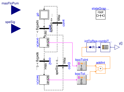
This model implements a simple staging control logic for variable speed pumps.
- When the mass flowrate in each pump is greater than a threshold, and the speed signal is greater than a threshold, then activate one more pump;
- When the mass flowrate in each pump is less than a threshold, or the speed signal is smaller than a threshold, then deactivate one more pump.
Extends from Modelica.Blocks.Icons.Block (Basic graphical layout of input/output block).
Parameters
| Type | Name | Default | Description |
|---|---|---|---|
| Time | tWai | Waiting time [s] | |
| MassFlowRate | m_flow_nominal | Nominal mass flow rate of the identical variable-speed pumps [kg/s] | |
| Real | minSpe | 0.05 | Minimum speed ratio required by variable speed pumps [1] |
| MassFlowRate | criPoiFlo | 0.7*m_flow_nominal | Critcal point of flowrate for switch pump on or off [kg/s] |
| MassFlowRate | deaBanFlo | 0.1*m_flow_nominal | Deadband for critical point of flowrate [kg/s] |
| Real | criPoiSpe | 0.5 | Critical point of speed signal for switching on or off |
| Real | deaBanSpe | 0.3 | Deadband for critical point of speed signal |
Connectors
| Type | Name | Description |
|---|---|---|
| input RealInput | masFloPum | Total mass flowrate in the variable speed pumps |
| input RealInput | speSig | Speed signal |
| output RealOutput | y[2] | On/off signal - 0: off; 1: on |
Modelica definition
model VariableSpeedPumpStage "Staging control for variable speed pumps"
extends Modelica.Blocks.Icons.Block;
parameter Modelica.Units.SI.Time tWai "Waiting time";
parameter Modelica.Units.SI.MassFlowRate m_flow_nominal
"Nominal mass flow rate of the identical variable-speed pumps";
parameter Real minSpe(unit="1",min=0,max=1) = 0.05
"Minimum speed ratio required by variable speed pumps";
parameter Modelica.Units.SI.MassFlowRate criPoiFlo=0.7*m_flow_nominal
"Critcal point of flowrate for switch pump on or off";
parameter Modelica.Units.SI.MassFlowRate deaBanFlo=0.1*m_flow_nominal
"Deadband for critical point of flowrate";
parameter Real criPoiSpe = 0.5
"Critical point of speed signal for switching on or off";
parameter Real deaBanSpe = 0.3
"Deadband for critical point of speed signal";
Modelica.Blocks.Interfaces.RealInput masFloPum
"Total mass flowrate in the variable speed pumps";
Modelica.Blocks.Interfaces.RealInput speSig
"Speed signal";
Modelica.Blocks.Interfaces.RealOutput y[2]
"On/off signal - 0: off; 1: on";
Modelica.StateGraph.Transition con1(
enableTimer=true,
waitTime=tWai,
condition=speSig > minSpe)
"Fire condition 1: free cooling to partially mechanical cooling";
Modelica.StateGraph.StepWithSignal oneOn(nIn=2, nOut=2)
"One chiller is commanded on";
Modelica.StateGraph.InitialStep off(nIn=1, nOut=1)
"Free cooling mode";
Modelica.StateGraph.StepWithSignal twoOn(nIn=1, nOut=1)
"Two chillers are commanded on";
Modelica.StateGraph.Transition con2(
enableTimer=true,
waitTime=tWai,
condition=speSig > criPoiSpe + deaBanSpe and
masFloPum > criPoiFlo + deaBanFlo)
"Fire condition 2: partially mechanical cooling to fully mechanical cooling";
Modelica.StateGraph.Transition con3(
enableTimer=true,
waitTime=tWai,
condition=speSig < criPoiSpe - deaBanSpe
or masFloPum < criPoiFlo - deaBanFlo)
"Fire condition 3: fully mechanical cooling to partially mechanical cooling";
Modelica.StateGraph.Transition con4(
enableTimer=true,
waitTime=tWai,
condition=speSig <= minSpe)
"Fire condition 4: partially mechanical cooling to free cooling";
inner Modelica.StateGraph.StateGraphRoot stateGraphRoot;
Modelica.Blocks.Tables.CombiTable1Ds combiTable1Ds(
table=[0,0,0;
1,1,0;
2,1,1])
"Determine which pump should be on - rotation control is not considered here";
Buildings.Controls.OBC.CDL.Conversions.BooleanToInteger booToInt(
final integerTrue=1,
final integerFalse=0);
Buildings.Controls.OBC.CDL.Conversions.BooleanToInteger booToInt1(
final integerFalse=0, final integerTrue=2);
Buildings.Controls.OBC.CDL.Integers.Add addInt;
Buildings.Controls.OBC.CDL.Conversions.IntegerToReal intToRea;
equation
connect(off.outPort[1], con1.inPort);
connect(con1.outPort, oneOn.inPort[1]);
connect(con2.inPort, oneOn.outPort[1]);
connect(con2.outPort, twoOn.inPort[1]);
connect(twoOn.outPort[1], con3.inPort);
connect(con4.outPort, off.inPort[1]);
connect(con3.outPort, oneOn.inPort[2]);
connect(con4.inPort, oneOn.outPort[2]);
connect(combiTable1Ds.y, y);
connect(booToInt.u, oneOn.active);
connect(twoOn.active, booToInt1.u);
connect(booToInt.y, addInt.u1);
connect(booToInt1.y, addInt.u2);
connect(addInt.y, intToRea.u);
connect(intToRea.y, combiTable1Ds.u);
end VariableSpeedPumpStage;
