Buildings.ThermalZones.EnergyPlus_9_6_0.Examples.SmallOffice.BaseClasses
Package with base classes
Information
This package contains base classes that are used to construct the models in Buildings.ThermalZones.EnergyPlus_9_6_0.Examples.SmallOffice.
Extends from Modelica.Icons.BasesPackage (Icon for packages containing base classes).
Package Content
| Name | Description |
|---|---|
| Model of a floor of the building | |
| Model of ideal heater or cooler |
 Buildings.ThermalZones.EnergyPlus_9_6_0.Examples.SmallOffice.BaseClasses.Floor
Model of a floor of the building

Information
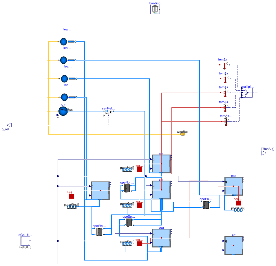
Model of a floor that consists of five thermal zones.
The five room model is representative of one floor of the new construction small office building for Chicago, IL, as described in the set of DOE Commercial Building Benchmarks (Deru et al, 2009). There are four perimeter zones and one core zone. The envelope thermal properties meet ASHRAE Standard 90.1-2004.
Each thermal zone can have air flow from the HVAC system, through leakages of the building envelope (except for the core zone) and through bi-directional air exchange through open doors that connect adjacent zones. The bi-directional air exchange is modeled based on the differences in static pressure between adjacent rooms at a reference height plus the difference in static pressure across the door height as a function of the difference in air density. Infiltration is a function of the flow imbalance of the HVAC system.
Implementation
Compared to the base class, which has been built for the models in Buildings.Examples.VAVReheat which are for a larger building, the instances of Buildings.Airflow.Multizone.DoorOpen are made smaller. Their length has been reduced proportionally to the difference in length of the walls of the core zone of the two buildings. See also Buildings.ThermalZones.EnergyPlus_9_6_0.Examples.SmallOffice for a description of the differences in these buildings.
References
Deru M., K. Field, D. Studer, K. Benne, B. Griffith, P. Torcellini, M. Halverson, D. Winiarski, B. Liu, M. Rosenberg, J. Huang, M. Yazdanian, and D. Crawley. DOE commercial building research benchmarks for commercial buildings. Technical report, U.S. Department of Energy, Energy Efficiency and Renewable Energy, Office of Building Technologies, Washington, DC, 2009.
Extends from Buildings.Examples.VAVReheat.BaseClasses.PartialFloor (Interface for a model of a floor of a building).
Parameters
| Type | Name | Default | Description |
|---|---|---|---|
| replaceable package Medium | PartialMedium | Medium model for air | |
| Boolean | use_windPressure | true | Set to true to enable wind pressure |
| Real | kIntNor | 1 | Gain factor to scale internal heat gain in north zone |
| Volume | VRooCor | 456.455 | Room volume corridor [m3] |
| Volume | VRooSou | 346.022 | Room volume south [m3] |
| Volume | VRooNor | 346.022 | Room volume north [m3] |
| Volume | VRooEas | 205.265 | Room volume east [m3] |
| Volume | VRooWes | 205.265 | Room volume west [m3] |
| Area | AFloCor | cor.AFlo | Floor area corridor [m2] |
| Area | AFloSou | sou.AFlo | Floor area south [m2] |
| Area | AFloNor | nor.AFlo | Floor area north [m2] |
| Area | AFloEas | eas.AFlo | Floor area east [m2] |
| Area | AFloWes | wes.AFlo | Floor area west [m2] |
| String | idfName | Modelica.Utilities.Files.loa... | Name of the IDF file |
| String | epwName | Modelica.Utilities.Files.loa... | Name of the weather file |
| String | weaName | Modelica.Utilities.Files.loa... | Name of the weather file |
Connectors
| Type | Name | Description |
|---|---|---|
| VesselFluidPorts_b | portsSou[2] | Fluid inlets and outlets |
| VesselFluidPorts_b | portsEas[2] | Fluid inlets and outlets |
| VesselFluidPorts_b | portsNor[2] | Fluid inlets and outlets |
| VesselFluidPorts_b | portsWes[2] | Fluid inlets and outlets |
| VesselFluidPorts_b | portsCor[2] | Fluid inlets and outlets |
| output RealOutput | TRooAir[5] | Room air temperatures [K] |
| output RealOutput | p_rel | Relative pressure signal of building static pressure |
| Bus | weaBus | Weather bus |
| HeatPort_a | heaPorSou | Heat port to air volume South |
| HeatPort_a | heaPorEas | Heat port to air volume East |
| HeatPort_a | heaPorNor | Heat port to air volume North |
| HeatPort_a | heaPorWes | Heat port to air volume West |
| HeatPort_a | heaPorCor | Heat port to air volume corridor |
Modelica definition
 Buildings.ThermalZones.EnergyPlus_9_6_0.Examples.SmallOffice.BaseClasses.IdealHeaterCooler
Model of ideal heater or cooler

Information
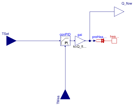
Model of an ideal heater or cooler that tracks a set point using a PI controller. The heater or cooler has a PID controller that regulates the heat added or removed.
To use this model, connect its heat port to the heat port of an air volume, for example,
the heat port heaPorAir of
Buildings.ThermalZones.EnergyPlus_9_6_0.ThermalZone.
Note that this model can only provide sensible cooling, but no latent cooling.
Extends from Modelica.Blocks.Icons.Block (Basic graphical layout of input/output block).
Parameters
| Type | Name | Default | Description |
|---|---|---|---|
| HeatFlowRate | Q_flow_nominal | Maximum heat flow rate (positive for heating; negative for cooling) [W] | |
| Controller | |||
| SimpleController | controllerType | Buildings.Controls.OBC.CDL.T... | Type of controller |
| Real | k | 1 | Gain of controller |
| Real | Ti | 120 | Time constant of integrator block [s] |
| Real | Td | 0.1 | Time constant of derivative block [s] |
Connectors
| Type | Name | Description |
|---|---|---|
| input RealInput | TSet | Set point temperature |
| input RealInput | TMea | Measured temperature |
| output RealOutput | Q_flow | Heat flow rate [W] |
| HeatPort_b | heaPor | Heat port |
