Buildings.Fluid.FixedResistances.Validation.PlugFlowPipes.Data.BaseClasses
BaseClasses for data records
Information
This package contains base classes that are used to construct the models in Buildings.Fluid.FixedResistances.Validation.PlugFlowPipes.Data.
Extends from Modelica.Icons.BasesPackage (Icon for packages containing base classes).
Package Content
| Name | Description |
|---|---|
| BaseClass for experimental data from the pipe test bench | |
| Base class for ULg experimental data |
 Buildings.Fluid.FixedResistances.Validation.PlugFlowPipes.Data.BaseClasses.PipeDataBaseDefinition
BaseClass for experimental data from the pipe test bench
Information
Defines basic record of experimental data with n measured points.
The first column corresponds to time, further columns to measured data.
Extends from Modelica.Icons.Record (Icon for records).
Parameters
| Type | Name | Default | Description |
|---|---|---|---|
| Integer | nCol | Number of columns in the data file | |
| String | filNam | Name of data file |
Modelica definition
 Buildings.Fluid.FixedResistances.Validation.PlugFlowPipes.Data.BaseClasses.PipeDataULg
Base class for ULg experimental data
Information
This record contains information of an aproximately 15 minutes long test bench carried out at the University of Liège.
Data structure
Column 1: Time in s
Column 2: Mass flow rate in kg/s
Column 3: Outlet pipe temperature in °C
Column 4: Outlet water temperature in °C
Column 5: Inlet pipe temperature in °C
Column 6: Inlet water temperature in °C
Test procedure
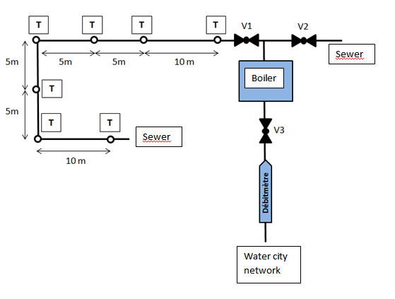
Before to perform a test, the water city network is pushed inside the approximately 39 meter long studied pipe during about 10 minutes to be sure that it is at the same temperature. During this time period, valves V3 and V1 are opened, the boiler is off and the valve V2 is closed.
Then, the valve V1 is closed and the valve V2 and V3 are opened. The boiler is started to reach the setpoint hot water temperature. When the temperature setpoint is achieved, data starts to be recorded, the valve V1 is opened and the valve V2 is closed at the same time to supply the studied pipe in hot water. After the outlet pipe temperature is stabilized, the boiler is shut off.
During the test, the ambient temperature is equal to 18°C and the mass flow rate is set to 1.245 kg/s.
Test bench schematic

Notice: length are approximate
Pipe characteristics
- Metal density about 7800 kg/m3
- Specific heat capacity about 480 J/kg/K
- Thickness 3.91 mm (Outer diameter 0.0603 m)
- Inner diameter: 0.05248 m
- Roughness is currently neglected
- Initial temperature of the pipe is considered equal to the initial temperature of the water (cooling before test)
- Heat transfer coefficient between the pipe and the ambient is assumed at 5 W/m2K (from internal model) due to insulation. The pipe is insulated by Tubolit 60/13 (13mm of thickness) whose nominal thermal coefficient is inferior 0.04. Notice the insulation is quite aged therefore the nominal thermal coefficient could be higher
- Heat transfer coefficient between water and pipe is a function of the fluid temperature (determined by EES software).
Extends from PipeDataBaseDefinition (BaseClass for experimental data from the pipe test bench).
Parameters
| Type | Name | Default | Description |
|---|---|---|---|
| Integer | nCol | Number of columns in the data file | |
| String | filNam | Name of data file | |
| Temperature_degC | T_start_in | 20 | Initial temperature at inlet [degC] |
| Temperature_degC | T_start_out | 20 | Initial temperature at outlet [degC] |
| MassFlowRate | m_flowIni | 0 | Mass flow initialization [kg/s] |
