Buildings.Fluid.HeatExchangers.DXCoils.BaseClasses
Package with base classes for DX cooling coil model
Information
This package contains base classes that are used to construct the models in Buildings.Fluid.HeatExchangers.DXCoils.Extends from Modelica.Icons.BasesPackage (Icon for packages containing base classes).
Package Content
| Name | Description |
|---|---|
| Calculates air properties at apparatus dew point | |
| Calculates air properties at dry coil surface | |
| Calculates rate of condensation | |
| Calculates cooling capacity at given temperature and flow fraction for air-cooled coils | |
| Calculates cooling capacity at given temperature and flow fraction for water-cooled DX coils | |
| DX cooling coil operation | |
| Calculates dry coil condition | |
| Selects results from dry or wet coil | |
| A partial block for essential parameters | |
| Model that computes evaporation of water that accumulated on the coil surface | |
| Electrical power consumed by the unit | |
| Partial block for dry and wet coil conditions | |
| Partial block for DX coil | |
| Calculates performance curve value at given temperature and mass flow rate | |
| Partial model for DX coil | |
| Partial block for apparatus dew and dry point calculation | |
| Base class for water-cooled DX coils | |
| Calculates the sensible heat ratio | |
| Selects the lower specified speed ratio for multispeed model | |
| Interpolates values between speeds | |
| Calculates UA/Cp of the coil | |
| Calculates wet coil condition | |
| Package with functions | |
| Package with examples of base class components for DX cooling coil model |
 Buildings.Fluid.HeatExchangers.DXCoils.BaseClasses.ApparatusDewPoint
Calculates air properties at apparatus dew point
Information
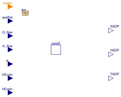
This blocks outputs the state of the moist air at the dew point of the coil. The bypass factor of the coil and the resulting enthalpy difference is computed by its base class Buildings.Fluid.HeatExchangers.DXCoils.BaseClasses.PartialSurfaceCondition.
Extends from Buildings.Fluid.HeatExchangers.DXCoils.BaseClasses.PartialSurfaceCondition (Partial block for apparatus dew and dry point calculation).
Parameters
| Type | Name | Default | Description |
|---|---|---|---|
| DXCoil | datCoi | redeclare parameter Building... | Performance data |
| replaceable package Medium | PartialCondensingGases | Medium model | |
| Boolean | variableSpeedCoil | Flag, set to true to interpolate data | |
| Initialization | |||
| Real | bypass.start | 0.25 | Bypass factor |
Connectors
| Type | Name | Description |
|---|---|---|
| input RealInput | speRat | Speed index |
| input RealInput | Q_flow | Cooling capacity of the coil [W] |
| input RealInput | m_flow | Evaporator air mass flow rate [kg/s] |
| input RealInput | p | Evaporator air static pressure [Pa] |
| input RealInput | XEvaIn | Evaporator inlet air mass fraction |
| input RealInput | hEvaIn | Evaporator air inlet specific enthalpy [J/kg] |
| input IntegerInput | stage | Stage of coil, or 0/1 for variable-speed coil |
| output RealOutput | hADP | Specific enthalpy of air at apparatus dew point [J/kg] |
| output RealOutput | XADP | Humidity mass fraction of air at apparatus dew point |
| output RealOutput | TADP | Dry bulb temperature of air at apparatus dew point [K] |
Modelica definition
 Buildings.Fluid.HeatExchangers.DXCoils.BaseClasses.ApparatusDryPoint
Calculates air properties at dry coil surface
Information
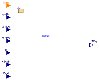
This blocks outputs the state of the moist air at of the coil, assuming no condensation occurs. The bypass factor of the coil and the resulting enthalpy difference is computed by its base class Buildings.Fluid.HeatExchangers.DXCoils.BaseClasses.PartialSurfaceCondition.
Extends from Buildings.Fluid.HeatExchangers.DXCoils.BaseClasses.PartialSurfaceCondition (Partial block for apparatus dew and dry point calculation).
Parameters
| Type | Name | Default | Description |
|---|---|---|---|
| DXCoil | datCoi | redeclare parameter Building... | Performance data |
| replaceable package Medium | PartialCondensingGases | Medium model | |
| Boolean | variableSpeedCoil | Flag, set to true to interpolate data | |
| Initialization | |||
| Real | bypass.start | 0.25 | Bypass factor |
Connectors
| Type | Name | Description |
|---|---|---|
| input RealInput | speRat | Speed index |
| input RealInput | Q_flow | Cooling capacity of the coil [W] |
| input RealInput | m_flow | Evaporator air mass flow rate [kg/s] |
| input RealInput | p | Evaporator air static pressure [Pa] |
| input RealInput | XEvaIn | Evaporator inlet air mass fraction |
| input RealInput | hEvaIn | Evaporator air inlet specific enthalpy [J/kg] |
| input IntegerInput | stage | Stage of coil, or 0/1 for variable-speed coil |
| output RealOutput | TDry | Dry bulb temperature of air at dry coil condition [K] |
Modelica definition
 Buildings.Fluid.HeatExchangers.DXCoils.BaseClasses.Condensation
Calculates rate of condensation

Information
This block computes the water mass flow rate that condenses.
Extends from Modelica.Blocks.Icons.Block (Basic graphical layout of input/output block).
Connectors
| Type | Name | Description |
|---|---|---|
| input RealInput | Q_flow | Heat flow [W] |
| input RealInput | SHR | Sensible heat ratio |
| output RealOutput | mWat_flow | Mass flow rate of water condensed at cooling coil [kg/s] |
Modelica definition
 Buildings.Fluid.HeatExchangers.DXCoils.BaseClasses.CoolingCapacityAirCooled
Calculates cooling capacity at given temperature and flow fraction for air-cooled coils
Information
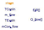
This model calculates cooling capacity and EIR for air-cooled DX coils in off-designed conditions based on performance modifers calculated in partial model Buildings.Fluid.HeatExchangers.DXCoils.BaseClasses.PartialCoolingCapacity.
Cooling capacity
The cooling capacity modifiers are multiplied with nominal cooling capacity to obtain the cooling capacity of the coil at given inlet temperatures and mass flow rate as
Q̇(θe,in, θc,in, ff) = capθ(θe,in, θc,in) capFF(ff) Q̇nom,
where θe,in is the evaporator inlet temperature and θc,in is the condenser inlet temperature in degrees Celsius. θe,in is the dry-bulb temperature if the coil is dry, or the wet-bulb temperature if the coil is wet. capθ(θe,in, θc,in) is cooling capacity modifier as a function of temperature. capFF(ff) is cooling capacity modifier as a function of nomalized mass flowrate at the evaporator.
Energy Input Ratio (EIR)
The Energy Input Ratio (EIR) is the inverse of the Coefficient of Performance (COP). Similar to the cooling rate, the EIR of the coil is the product of a function that takes into account changes in condenser and evaporator inlet temperatures, and changes in mass flow rate. The EIR is computed as
EIR(θe,in, θc,in, ff) = EIRθ(θe,in, θc,in) EIRFF(ff) ⁄ COPnominal
Extends from Buildings.Fluid.HeatExchangers.DXCoils.BaseClasses.PartialCoolingCapacity (Calculates performance curve value at given temperature and mass flow rate).
Parameters
| Type | Name | Default | Description |
|---|---|---|---|
| Boolean | use_mCon_flow | false | Set to true to enable connector for the condenser mass flow rate |
| Integer | nSta | Number of coil stages (not counting the off stage) | |
| Initialization | |||
| Real | cap_T.start[nSta] | 1 | Cooling capacity modification factor as a function of temperature |
| Real | cap_FF.start[nSta] | 1 | Cooling capacity modification factor as a function of flow fraction |
| Real | EIR_T.start[nSta] | 1 | EIR modification factor as a function of temperature |
| Real | EIR_FF.start[nSta] | 1 | EIR modification factor as a function of flow fraction |
| Real | corFac.start[nSta] | 1 | Correction factor that is one inside the valid flow fraction, and attains zero below the valid flow fraction |
Connectors
| Type | Name | Description |
|---|---|---|
| input IntegerInput | stage | Stage of coil, or 0/1 for variable-speed coil |
| input RealInput | TConIn | Temperature of air entering the condenser coil [K] |
| input RealInput | m_flow | Air mass flow rate at the evaporator [kg/s] |
| input RealInput | TEvaIn | Temperature of air entering the evaporator (wet bulb for wet coil and dry bulb for dry coil) [K] |
| input RealInput | mCon_flow | Water mass flow rate at the condenser [kg/s] |
| output RealOutput | Q_flow[nSta] | Total cooling capacity [W] |
| output RealOutput | EIR[nSta] | Energy Input Ratio |
Modelica definition
 Buildings.Fluid.HeatExchangers.DXCoils.BaseClasses.CoolingCapacityWaterCooled
Calculates cooling capacity at given temperature and flow fraction for water-cooled DX coils
Information
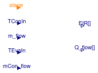
This model calculates cooling capacity and EIR at off-designed conditions for water-cooled DX coils. The difference between air-cooled and water-cooled DX coils is that water-cooled DX coils require two additional modifer curves for total cooling capacity and EIR as a function of water mass flowrate at the condensers.
Total Cooling Capacity
The total cooling capacity at off-designed conditions for water-cooled DX coils is calculated as:
Q̇(θe,in, θc,in, ff) = capθ(θe,in, θc,in) capFF(ff) capFFCon(ffCon) Q̇nom
where capFFCon(ffCon) is the additional modifier for cooling capacity, and calculated as:
capConFFCon(ffCon) = b1 + b2 ffCon + b3 ffCon2 + b4ffCon3 + ...
where the variable ffCon is the nomalized mass flow rate at the condenser, and calculated as:
ffCon = ṁCon ⁄ ṁConnom
where ṁCon is the mass flow rate at the condenser and ṁConnom is the nominal mass flow rate at the condenser.
Energy Input Ratio (EIR)
The Energy Input Ratio (EIR) is the inverse of the Coefficient of Performance (COP). Similar to the cooling capacity modifiers, the change in EIR due to change in water mass flow rate at the condenser is
EIRFFCon(ffCon) = b1 + b2 ffCon + b3 ffCon2 + b4ffCon3 + ...
where the six coefficients are obtained from the coil performance data record. See Buildings.Fluid.HeatExchangers.DXCoils.BaseClasses.PartialCoolingCapacity for more information.
Extends from Buildings.Fluid.HeatExchangers.DXCoils.BaseClasses.PartialCoolingCapacity (Calculates performance curve value at given temperature and mass flow rate).
Parameters
| Type | Name | Default | Description |
|---|---|---|---|
| Boolean | use_mCon_flow | true | Set to true to enable connector for the condenser mass flow rate |
| Integer | nSta | Number of coil stages (not counting the off stage) | |
| Initialization | |||
| Real | cap_T.start[nSta] | 1 | Cooling capacity modification factor as a function of temperature |
| Real | cap_FF.start[nSta] | 1 | Cooling capacity modification factor as a function of flow fraction |
| Real | EIR_T.start[nSta] | 1 | EIR modification factor as a function of temperature |
| Real | EIR_FF.start[nSta] | 1 | EIR modification factor as a function of flow fraction |
| Real | corFac.start[nSta] | 1 | Correction factor that is one inside the valid flow fraction, and attains zero below the valid flow fraction |
Connectors
| Type | Name | Description |
|---|---|---|
| input IntegerInput | stage | Stage of coil, or 0/1 for variable-speed coil |
| input RealInput | TConIn | Temperature of air entering the condenser coil [K] |
| input RealInput | m_flow | Air mass flow rate at the evaporator [kg/s] |
| input RealInput | TEvaIn | Temperature of air entering the evaporator (wet bulb for wet coil and dry bulb for dry coil) [K] |
| input RealInput | mCon_flow | Water mass flow rate at the condenser [kg/s] |
| output RealOutput | Q_flow[nSta] | Total cooling capacity [W] |
| output RealOutput | EIR[nSta] | Energy Input Ratio |
Modelica definition
 Buildings.Fluid.HeatExchangers.DXCoils.BaseClasses.DXCooling
DX cooling coil operation
Information
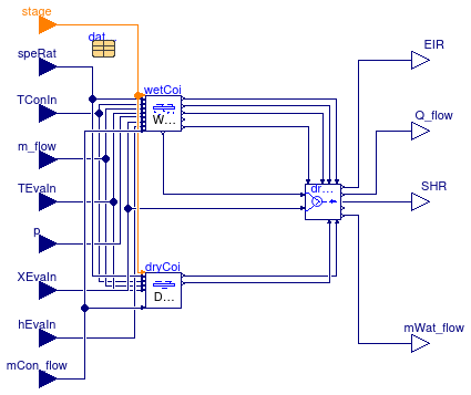
This block combines the models for the dry coil and the wet coil. Output of the block is the coil performance which, depending on the mass fraction at the apparatus dew point temperature and the mass fraction of the coil inlet air, may be from the dry coil, the wet coil, or a weighted average of the two.
Extends from Buildings.Fluid.HeatExchangers.DXCoils.BaseClasses.PartialCoilInterface (Partial block for DX coil).
Parameters
| Type | Name | Default | Description |
|---|---|---|---|
| DXCoil | datCoi | redeclare parameter Building... | Performance data |
| Boolean | use_mCon_flow | Set to true to enable connector for the condenser mass flow rate | |
| replaceable package Medium | Modelica.Media.Interfaces.Pa... | Medium model | |
| Boolean | variableSpeedCoil | Flag, set to true for coil with variable speed | |
Connectors
| Type | Name | Description |
|---|---|---|
| input IntegerInput | stage | Stage of coil, or 0/1 for variable-speed coil |
| input RealInput | speRat | Speed ratio |
| input RealInput | m_flow | Air mass flow rate |
| input RealInput | TEvaIn | Temperature of air entering the cooling coil |
| input RealInput | TConIn | Outside air dry bulb temperature for an air cooled condenser or wetbulb temperature for an evaporative cooled condenser [K] |
| output RealOutput | EIR | Energy Input Ratio |
| output RealOutput | Q_flow | Total cooling capacity [W] |
| input RealInput | mCon_flow | Water mass flow rate at condensers for water-cooled DX units |
| replaceable package Medium | Medium model | |
| output RealOutput | mWat_flow | Mass flow rate of water condensed at cooling coil [kg/s] |
| output RealOutput | SHR | Sensible Heat Ratio: Ratio of sensible heat load to total heat load |
| input RealInput | XEvaIn | Inlet air mass fraction |
| input RealInput | p | Pressure at inlet of coil |
| input RealInput | hEvaIn | Specific enthalpy of air entering the coil |
Modelica definition
 Buildings.Fluid.HeatExchangers.DXCoils.BaseClasses.DryCoil
Calculates dry coil condition
Information
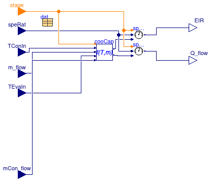
This block calculates the rate of cooling and the coil surface condition under the assumption that the coil is dry.
The wet coil conditions are computed in Buildings.Fluid.HeatExchangers.DXCoils.BaseClasses.WetCoil. See Buildings.Fluid.HeatExchangers.DXCoils.UsersGuide for an explanation of the model.
Extends from Buildings.Fluid.HeatExchangers.DXCoils.BaseClasses.PartialCoilCondition (Partial block for dry and wet coil conditions).
Parameters
| Type | Name | Default | Description |
|---|---|---|---|
| DXCoil | datCoi | redeclare parameter Building... | Performance data |
| Boolean | use_mCon_flow | Set to true to enable connector for the condenser mass flow rate | |
| Boolean | variableSpeedCoil | Flag, set to true for coil with variable speed | |
| CoolingCapacityAirCooled | cooCap | redeclare Buildings.Fluid.He... | Performance data |
| replaceable package Medium | Modelica.Media.Interfaces.Pa... | Medium model | |
Connectors
| Type | Name | Description |
|---|---|---|
| input IntegerInput | stage | Stage of coil, or 0/1 for variable-speed coil |
| input RealInput | speRat | Speed ratio |
| input RealInput | m_flow | Air mass flow rate |
| input RealInput | TEvaIn | Temperature of air entering the cooling coil |
| input RealInput | TConIn | Outside air dry bulb temperature for an air cooled condenser or wetbulb temperature for an evaporative cooled condenser [K] |
| output RealOutput | EIR | Energy Input Ratio |
| output RealOutput | Q_flow | Total cooling capacity [W] |
| input RealInput | mCon_flow | Water mass flow rate at condensers for water-cooled DX units |
| replaceable package Medium | Medium model | |
Modelica definition
 Buildings.Fluid.HeatExchangers.DXCoils.BaseClasses.DryWetSelector
Selects results from dry or wet coil
Information
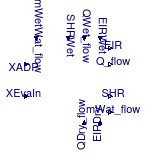
This block smoothly transitions the results from the dry coil and the wet coil computation. The independent variable for the transition is the difference between the water mass fractions at the apparatus dew point, as computed by the wet coil model, and the coil inlet mass fraction.
Connectors
| Type | Name | Description |
|---|---|---|
| input RealInput | XEvaIn | Inlet air mass fraction |
| input RealInput | XADP | Mass fraction at ADP |
| input RealInput | EIRWet | Energy Input Ratio |
| input RealInput | QWet_flow | Total cooling capacity [W] |
| input RealInput | SHRWet | Sensible Heat Ratio: Ratio of sensible heat load to total heat load |
| input RealInput | mWetWat_flow | Mass flow rate of water condensed at cooling coil [kg/s] |
| input RealInput | EIRDry | Energy Input Ratio |
| input RealInput | QDry_flow | Total cooling capacity [W] |
| output RealOutput | EIR | Energy Input Ratio |
| output RealOutput | Q_flow | Total cooling capacity [W] |
| output RealOutput | SHR | Sensible Heat Ratio: Ratio of sensible heat load to total heat load |
| output RealOutput | mWat_flow | Mass flow rate of water condensed at cooling coil [kg/s] |
Modelica definition
Buildings.Fluid.HeatExchangers.DXCoils.BaseClasses.EssentialParameters
A partial block for essential parameters

Information
This partial block declares parameters that are required by most classes in the package Buildings.Fluid.HeatExchangers.DXCoils.
Parameters
| Type | Name | Default | Description |
|---|---|---|---|
| DXCoil | datCoi | redeclare parameter Building... | Performance data |
Modelica definition
 Buildings.Fluid.HeatExchangers.DXCoils.BaseClasses.Evaporation
Model that computes evaporation of water that accumulated on the coil surface

Information
This model computes the water accumulation on the surface of a cooling coil. When the cooling coil operates, water is accumulated on the coil surface up to a maximum amount of water before water starts to drain away from the coil. When the coil is off, the accumulated water evaporates into the air stream.
Physical description
The calculations are based on Shirey et al. (2006).
Parameters
The maximum amount of water that can be accumulated is computed based on the following model, where we used the convention that latent heat removed from the air is negative: The parameter twet defines how long it takes for condensate to drip of the coil, assuming the coil starts completely dry and operates at the nominal operating point. Henderson et al. (2003) measured values for twet from 16.5 minutes (990 seconds) to 29 minutes (1740 seconds). Thus, we use a default value of twet=1400 seconds. The maximum amount of water that can accumulate on the coil is
mmax = -Q̇L,nom twet ⁄ hfg
where Q̇L,nom<0 is the latent capacity at the nominal conditions and hfg is the latent heat of evaporation.
When the coil is off, the water that has been accumulated on the coil evaporates into the air. The rate of water vapor evaporation at nominal operating conditions is defined by the parameter γnom. The definition of γnom is
γnom = Q̇e,nom ⁄ Q̇L,nom,
where Q̇e,nom<0 is the rate of evaporation from the coil surface into the air stream right after the coil is switched off. The default value is γnom = 1.5.
Time dependent calculations
First, we discuss the accumulation of water on the coil. The rate of water accumulation is computed as
dm(t)⁄dt = -ṁwat(t)
where ṁwat(t) ≤ 0 is the water vapor mass flow rate that is extracted from the air at the current operating conditions. The actual water vapor mass flow rate that is removed from the air stream is as computed by the steady-state cooling coil performance model because for the coil outlet conditions, it does not matter whether the water accumulates on the coil or drips away from the coil. The initial value for the water accumulation is zero at the start of the simulation, and set to whatever water remains after the coil has been switched off and the water partially or completely evaporated into the air stream.
Now, we discuss the evaporation of the water on the coil surface into the air when the coil is off. The model in Shirey et al. (2006) is based on the assumption that the wet coil acts as an evaporative cooler. The change of water on the coil is
dm(t)⁄dt = -ṁmax(t) η(t),
where ṁmax(t) > 0 is the maximum water mass flow rate from the coil to the air and η(t) ∈ [0, 1] is the mass transfer effectiveness. For an evaporative cooler,
η(t) = 1-exp(-NTU(t)),
where NTU(t)=(hA)m/Ċa are the number of mass transfer units and Ċa is the air capacity flow rate. The mass transfer coefficient (hA)m is assumed to be proportional to the wet coil area, which is assumed to be equal to the ratio m(t) ⁄ mmax(t). Hence,
(hA)m(t) ∝ m(t) ⁄ mmax(t).
Furthermore, the mass transfer coefficient depends on the velocity, and hence mass flow rate, as
(hA)m(t) ∝ ṁa(t)0.8,
where ṁa(t) is the current air mass flow rate, from which follows that
NTU(t) ∝ ṁa(t)-0.2.
Therefore, the water mass flow rate from the coil into the air stream is
ṁwat(t) = ṁmax(t) (1-exp(-K (m(t) ⁄ mtot) (ṁa(t) ⁄ ṁa,nom)-0.2 )),
where K > 0 is a constant to be determined below and the rate of change of water on the coil surface is as before
dm(t)⁄dt = -ṁwat(t).
The maximum mass transfer is
ṁmax = ṁa (xwb(t) - x(t)),
where xwb(t) is the moisture content of air at the wet bulb state and x(t) is the actual moisture content of the air.
The constant K is determined from the nominal conditions as follows: At the nominal condition, we have m(t) ⁄ mtot=1 and ṁa(t) ⁄ ṁa,nom=1, and, hence,
ṁnom = ṁmax,nom (1-e-K).
Because
ṁnom = - γ Q̇L,nom ⁄ hfg,
it follows that
K = -ln( 1 + γnom Q̇L,nom ⁄ ṁa,nom ⁄ hfg ⁄ (xwb,nom-xnom) ),
where xnom is the humidity ratio at the coil at nominal condition and xwb,nom is the humidity ratio at the wet bulb condition. Note that the ln(·) in the above equation requires that the argument is positive. See the implementation section below for how this is implemented.
Implementation
Potential for moisture transfer
For the potential that causes the moisture transfer, the difference in mass fraction between the current coil air and the coil air at the wet bulb conditions is used, provided that the air mass flow rate is within 1⁄3 of the nominal mass flow rate. For smaller air mass flow rates, the outlet conditions are used to ensure that the outlet conditions are not supersaturated air. The transition between these two driving potential is continuously differentiable in the mass flow rate.
Computation of mass transfer effectiveness
To evaluate
K = -ln( 1 + γnom Q̇L,nom ⁄ ṁa,nom ⁄ hfg ⁄ (xwb,nom-xnom) ),
the argument of the ln(·) function must be positive. However, often the parameter γnom is not known, and the default value of γnom = 1.5 may yield negative arguments for the function ln(·). We therefore set a lower bound on γnom as follows: Note that γnom must be such that 0 < ṁwat,nom < ṁmax,nom. This condition is equivalent to
0 < γnom < ṁa,nom (xwb,nom-xnom) hfg ⁄ (-Q̇L,nom)
If γnom were equal to the right hand side, then the mass transfer effectiveness would be one. Hence, we set the maximum value of γnom,max to
γnom,max = 0.8 ṁa,nom (xwb,nom-xnom) hfg ⁄ Q̇L,nom,
which corresponds to a mass transfer effectiveness of 0.8. If γnom > γnom,max, the model sets γnom=γnom,max and writes a warning message.
Regularization near zero air mass flow rate
To regularize the equations near zero air mass flow rate and zero humidity on the coil, the following conditions have been imposed in such a way that the model is once continuously differentiable with bounded derivatives on compact sets:
- We impose that ṁwat(t) → 0 as m → 0 to ensure that there is no evaporation if no water remains on the coil.
- We impose that ṁwat(t) ⁄ ṁa(t) → 0 as ṁa(t) → 0 to ensure that the evaporation mass flow rate remains bounded at zero air flow rate and that it is symmetric near zero without having to trigger an event.
This is implemented by replacing for |ṁa(t)| < δ the equation for the evaporation mass flow rate by
ṁwat(t) = C m ṁa2(t) (xwb,nom-xnom),
where C=K δ-0.2 which approximates continuity at |ṁa|=δ. Note that differentiability is ensured because the two equations are combined using the function Buildings.Utilities.Math.Functions.spliceFunction. Also note that based on physics, we would not have to square ṁa, but this was done to avoid an event that would be triggered if |ṁa| would have been used. Since the equation is active only at very small air flow rates when the fan is off, the error is negligible for typical applications.
References
Hugh I. Henderson, Jr., Don B. Shirey III and Richard A. Raustad. Understanding the Dehumidification Performance of Air-Conditioning Equipment at Part-Load Conditions. CIBSE/ASHRAE Conference, Edinburgh, Scotland, September 2003.
Don B. Shirey III, Hugh I. Henderson, Jr. and Richard A. Raustad. Understanding the Dehumidification Performance of Air-Conditioning Equipment at Part-Load Conditions. Florida Solar Energy Center, Technical Report FSEC-CR-1537-05, January 2006.
Extends from Modelica.Blocks.Icons.Block (Basic graphical layout of input/output block).
Parameters
| Type | Name | Default | Description |
|---|---|---|---|
| replaceable package Medium | Modelica.Media.Interfaces.Pa... | Medium model | |
| NominalValues | nomVal | Nominal values | |
| Boolean | computeReevaporation | true | Set to true to compute reevaporation of water that accumulated on coil |
| Advanced | |||
| MassFlowRate | mAir_flow_small | 0.1*abs(nomVal.m_flow_nominal) | Small mass flow rate for regularization of zero flow [kg/s] |
Connectors
| Type | Name | Description |
|---|---|---|
| replaceable package Medium | Medium model | |
| input BooleanInput | on | Control signal, true if compressor is on |
| input RealInput | mWat_flow | Water flow rate added into the medium [kg/s] |
| input RealInput | mAir_flow | Air mass flow rate [kg/s] |
| input RealInput | XEvaOut | Water mass fraction [1] |
| input RealInput | TEvaOut | Air temperature [K] |
| output RealOutput | mTotWat_flow | Total moisture mass flow rate into the air stream [kg/s] |
Modelica definition
 Buildings.Fluid.HeatExchangers.DXCoils.BaseClasses.InputPower
Electrical power consumed by the unit

Information
This block calculates total electrical energy consumed by the unit using the rate of cooling and the energy input ratio EIR.
The electrical energy consumed by the unit is
P = -Qcool EIR
Extends from Modelica.Blocks.Icons.Block (Basic graphical layout of input/output block).
Connectors
| Type | Name | Description |
|---|---|---|
| input RealInput | Q_flow | Cooling capacity of the coil [W] |
| input RealInput | EIR | Energy input ratio |
| input RealInput | SHR | Sensible heat ratio |
| output RealOutput | P | Electrical power consumed by the unit [W] |
| output RealOutput | QSen_flow | Sensible heat flow rate [W] |
| output RealOutput | QLat_flow | Latent heat flow rate [W] |
Modelica definition
 Buildings.Fluid.HeatExchangers.DXCoils.BaseClasses.PartialCoilCondition
Partial block for dry and wet coil conditions
Information
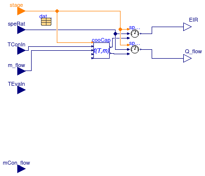
This partial block is the base class for Buildings.Fluid.HeatExchangers.DXCoils.BaseClasses.DryCoil and Buildings.Fluid.HeatExchangers.DXCoils.BaseClasses.WetCoil.
Extends from Buildings.Fluid.HeatExchangers.DXCoils.BaseClasses.PartialCoilInterface (Partial block for DX coil).
Parameters
| Type | Name | Default | Description |
|---|---|---|---|
| DXCoil | datCoi | redeclare parameter Building... | Performance data |
| Boolean | use_mCon_flow | Set to true to enable connector for the condenser mass flow rate | |
| Boolean | variableSpeedCoil | Flag, set to true for coil with variable speed | |
| CoolingCapacityAirCooled | cooCap | redeclare Buildings.Fluid.He... | Performance data |
Connectors
| Type | Name | Description |
|---|---|---|
| input IntegerInput | stage | Stage of coil, or 0/1 for variable-speed coil |
| input RealInput | speRat | Speed ratio |
| input RealInput | m_flow | Air mass flow rate |
| input RealInput | TEvaIn | Temperature of air entering the cooling coil |
| input RealInput | TConIn | Outside air dry bulb temperature for an air cooled condenser or wetbulb temperature for an evaporative cooled condenser [K] |
| output RealOutput | EIR | Energy Input Ratio |
| output RealOutput | Q_flow | Total cooling capacity [W] |
| input RealInput | mCon_flow | Water mass flow rate at condensers for water-cooled DX units |
Modelica definition
 Buildings.Fluid.HeatExchangers.DXCoils.BaseClasses.PartialCoilInterface
Partial block for DX coil
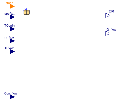
Information
This partial block declares the inputs and outputs that are common for Buildings.Fluid.HeatExchangers.DXCoils.BaseClasses.DryCoil and Buildings.Fluid.HeatExchangers.DXCoils.BaseClasses.DXCooling.
Extends from Modelica.Blocks.Icons.Block (Basic graphical layout of input/output block), Buildings.Fluid.HeatExchangers.DXCoils.BaseClasses.EssentialParameters (A partial block for essential parameters).
Parameters
| Type | Name | Default | Description |
|---|---|---|---|
| DXCoil | datCoi | redeclare parameter Building... | Performance data |
| Boolean | use_mCon_flow | Set to true to enable connector for the condenser mass flow rate |
Connectors
| Type | Name | Description |
|---|---|---|
| input IntegerInput | stage | Stage of coil, or 0/1 for variable-speed coil |
| input RealInput | speRat | Speed ratio |
| input RealInput | m_flow | Air mass flow rate |
| input RealInput | TEvaIn | Temperature of air entering the cooling coil |
| input RealInput | TConIn | Outside air dry bulb temperature for an air cooled condenser or wetbulb temperature for an evaporative cooled condenser [K] |
| output RealOutput | EIR | Energy Input Ratio |
| output RealOutput | Q_flow | Total cooling capacity [W] |
| input RealInput | mCon_flow | Water mass flow rate at condensers for water-cooled DX units |
Modelica definition
 Buildings.Fluid.HeatExchangers.DXCoils.BaseClasses.PartialCoolingCapacity
Calculates performance curve value at given temperature and mass flow rate

Information
Cooling capacity modifiers
There are two cooling capacity modifier functions: The function capθ accounts for a performance change due to different temperatures at the condenser and evaporator and the function capFF accounts for a performance change due to different air flow rates at the evaporator, relative to the nominal condition. These cooling capacity modifiers are multiplied with nominal cooling capacity to obtain the cooling capacity of the coil at given inlet temperatures and mass flow rate. See Buildings.Fluid.HeatExchangers.DXCoils.BaseClasses.CoolingCapacityAirCooled.
The temperature dependent cooling capacity modifier function is
capθ(θe,in, θc,in) = a1 + a2 θe,in + a3 θe,in 2 + a4 θc,in + a5 θc,in 2 + a6 θe,in θc,in,
where the six coefficients are obtained from the coil performance data record.
The flow fraction dependent cooling capacity modifier function is a polynomial with the normalized mass flow rate ff (flow fraction) at the evaporator as the time dependent variable. The normalized mass flow rate is defined as
ff = ṁ ⁄ ṁnom,
where ṁ is the mass flow rate at the evaporator and ṁnom is the nominal mass flow rate. If the coil has multiple stages, then the nominal mass flow rate of the respective stage is used. Hence,
capFF(ff) = b1 + b2 ff + b3 ff2 + b4ff3 + ...
The coefficients of the equation are obtained from the coil performance data record.
It is important to specify limits of the flow fraction to ensure validity of the capFF(⋅) function in performance record. A non-zero value of capFF(0) will lead to an infinite large change in fluid temperatures because Q̇ ≠ 0 but ṁ = 0. Hence, when ṁ ≠ 0 is below the valid range of the flow modifier function, the coil capacity will be reduced and set to zero near ṁ = 0.
Energy Input Ratio (EIR) modifiers
The Energy Input Ratio (EIR) is the inverse of the Coefficient of Performance (COP). Similar to the cooling rate, the EIR of the coil is the product of a function that takes into account changes in condenser and evaporator inlet temperatures, and changes in mass flow rate.
As for the cooling rate, EIRθ(⋅, ⋅) is
EIRθ(θe,in, θc,in) = c1 + c2 θe,in + c3 θe,in 2 + c4 θc,in + c5 θc,in 2 + c6 θe,in θc,in.
where the six coefficients are obtained from the coil performance data record, and θe,in is the dry-bulb temperature if the coil is dry, or the wet-bulb temperature otherwise.
Similar to the cooling ratio, the change in EIR due to a change in air mass flow rate is
EIRFF(ff) = d1 + d2 ff + d3 ff2 + d4ff3 + ...
Obtaining the polynomial coefficients
The package Buildings.Fluid.HeatExchangers.DXCoils.AirCooled.Examples.PerformanceCurves contains performance curves. Alternatively, users can enter their own performance curves by making an instance of a curve in Buildings.Fluid.HeatExchangers.DXCoils.AirCooled.Examples.PerformanceCurves and specifying custom coefficients for the above polynomials. The polynomial coefficients can be obtained by doing a curve fit that fits the polynomials to a set of data. The site http://www.scipy.org/Cookbook/FittingData shows examples for how to fit data. If a coil has multiple stages, then the fit need to be done for each stage. For variable frequency coils, multiple fits need to be done for user selected compressor speeds. For intermediate speeds, the performance data will be interpolated by the model Buildings.Fluid.HeatExchangers.DXCoils.AirCooled.VariableSpeed.
The table below shows the polynomials explained above, the name of the polynomial coefficients in Buildings.Fluid.HeatExchangers.DXCoils.AirCooled.Examples.PerformanceCurves and the independent parameters against which the data need to be fitted.
| Modelica name of coefficient in data record | Polynomial of the above info section | Parameters for curve fit |
|---|---|---|
capFunT |
capθ(θe,in, θc,in) = a1 + a2 θe,in + a3 θe,in 2 + a4 θc,in + a5 θc,in 2 + a6 θe,in θc,in | capθ, θe,in, θc,in |
capFunFF |
capFF(ff) = b1 + b2 ff + b3 ff2 + b4ff3 + ... | capFF, ff |
EIRFunT |
EIRθ(θe,in, θc,in) = a1 + a2 θe,in + a3 θe,in 2 + a4 θc,in + a5 θc,in 2 + a6 θe,in θc,in | EIRθ, θe,in, θc,in |
EIRFunFF |
EIRFF(ff) = b1 + b2 ff + b3 ff2 + b4ff3 + ... | EIRFF, ff |
Note that for the above polynomials, the units for temperature is degree Celsius and not Kelvins.
Implementation
A parameter of the performance curve is the range of mass flow fraction ff for which the data are valid. Below this range, this model reduces the cooling capacity and the energy input ratio so that both are zero if ff < ffmin/4, where ffmin is the minimum flow fraction for which the performance curves are valid.
Extends from Modelica.Blocks.Icons.Block (Basic graphical layout of input/output block).
Parameters
| Type | Name | Default | Description |
|---|---|---|---|
| Boolean | use_mCon_flow | Set to true to enable connector for the condenser mass flow rate | |
| Integer | nSta | Number of coil stages (not counting the off stage) | |
| Stage | sta[nSta] | redeclare parameter Building... | Performance data for this stage |
Connectors
| Type | Name | Description |
|---|---|---|
| input IntegerInput | stage | Stage of coil, or 0/1 for variable-speed coil |
| input RealInput | TConIn | Temperature of air entering the condenser coil [K] |
| input RealInput | m_flow | Air mass flow rate at the evaporator [kg/s] |
| input RealInput | TEvaIn | Temperature of air entering the evaporator (wet bulb for wet coil and dry bulb for dry coil) [K] |
| input RealInput | mCon_flow | Water mass flow rate at the condenser [kg/s] |
| output RealOutput | Q_flow[nSta] | Total cooling capacity [W] |
| output RealOutput | EIR[nSta] | Energy Input Ratio |
Modelica definition
 Buildings.Fluid.HeatExchangers.DXCoils.BaseClasses.PartialDXCoil
Partial model for DX coil
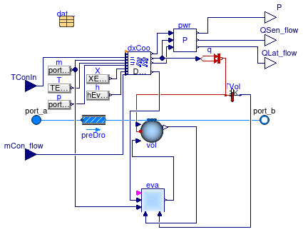
Information
This partial model is the base class for Buildings.Fluid.HeatExchangers.DXCoils.AirCooled.SingleSpeed Buildings.Fluid.HeatExchangers.DXCoils.AirCooled.MultiStage and Buildings.Fluid.HeatExchangers.DXCoils.AirCooled.VariableSpeed.
See Buildings.Fluid.HeatExchangers.DXCoils.UsersGuide for an explanation of the model.
Extends from Buildings.Fluid.HeatExchangers.DXCoils.BaseClasses.EssentialParameters (A partial block for essential parameters), Buildings.Fluid.Interfaces.TwoPortHeatMassExchanger (Partial model transporting one fluid stream with storing mass or energy).
Parameters
| Type | Name | Default | Description |
|---|---|---|---|
| DXCoil | datCoi | redeclare parameter Building... | Performance data |
| replaceable package Medium | PartialMedium | Medium in the component | |
| Boolean | use_mCon_flow | Set to true to enable connector for the condenser mass flow rate | |
| String | substanceName | "water" | Name of species substance |
| Nominal condition | |||
| MassFlowRate | m_flow_nominal | datCoi.sta[nSta].nomVal.m_fl... | Nominal mass flow rate [kg/s] |
| PressureDifference | dp_nominal | Pressure difference [Pa] | |
| Assumptions | |||
| Boolean | allowFlowReversal | true | = false to simplify equations, assuming, but not enforcing, no flow reversal |
| Advanced | |||
| MassFlowRate | m_flow_small | 1E-4*abs(m_flow_nominal) | Small mass flow rate for regularization of zero flow [kg/s] |
| Diagnostics | |||
| Boolean | show_T | false | = true, if actual temperature at port is computed |
| Flow resistance | |||
| Boolean | from_dp | false | = true, use m_flow = f(dp) else dp = f(m_flow) |
| Boolean | linearizeFlowResistance | false | = true, use linear relation between m_flow and dp for any flow rate |
| Real | deltaM | 0.1 | Fraction of nominal flow rate where flow transitions to laminar |
| Dynamics | |||
| Nominal condition | |||
| Time | tau | 30 | Time constant at nominal flow (if energyDynamics <> SteadyState) [s] |
| Conservation equations | |||
| Dynamics | energyDynamics | Modelica.Fluid.Types.Dynamic... | Type of energy balance: dynamic (3 initialization options) or steady state |
| Moisture balance | |||
| Boolean | computeReevaporation | true | Set to true to compute reevaporation of water that accumulated on coil |
| Initialization | |||
| AbsolutePressure | p_start | Medium.p_default | Start value of pressure [Pa] |
| Temperature | T_start | Medium.T_default | Start value of temperature [K] |
| MassFraction | X_start[Medium.nX] | Medium.X_default | Start value of mass fractions m_i/m [kg/kg] |
| ExtraProperty | C_start[Medium.nC] | fill(0, Medium.nC) | Start value of trace substances |
Connectors
| Type | Name | Description |
|---|---|---|
| replaceable package Medium | Medium in the component | |
| FluidPort_a | port_a | Fluid connector a (positive design flow direction is from port_a to port_b) |
| FluidPort_b | port_b | Fluid connector b (positive design flow direction is from port_a to port_b) |
| input RealInput | TConIn | Outside air dry bulb temperature for an air cooled condenser or wetbulb temperature for an evaporative cooled condenser [K] |
| input RealInput | mCon_flow | Water mass flow rate for condenser [kg/s] |
| output RealOutput | P | Electrical power consumed by the unit [W] |
| output RealOutput | QSen_flow | Sensible heat flow rate [W] |
| output RealOutput | QLat_flow | Latent heat flow rate [W] |
Modelica definition
 Buildings.Fluid.HeatExchangers.DXCoils.BaseClasses.PartialSurfaceCondition
Partial block for apparatus dew and dry point calculation
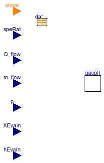
Information
This partial block is the base class for Buildings.Fluid.HeatExchangers.DXCoils.BaseClasses.ApparatusDewPoint and Buildings.Fluid.HeatExchangers.DXCoils.BaseClasses.ApparatusDryPoint.
This block calculates the UA/cp value, the bypass factor and the enthalpy difference across the coil. It uses the function Buildings.Fluid.HeatExchangers.DXCoils.BaseClasses.Functions.speedShift for intermediate compressor speeds.
Implementation
For coils that only have discrete compressor speeds, this block does not do an interpolation for intermediate speeds. For coils with variable speed compressors, the computations are also done if the coil is off, as this ensures that the derivatives are continuous near the off conditions.
Extends from Modelica.Blocks.Icons.Block (Basic graphical layout of input/output block), Buildings.Fluid.HeatExchangers.DXCoils.BaseClasses.EssentialParameters (A partial block for essential parameters).
Parameters
| Type | Name | Default | Description |
|---|---|---|---|
| DXCoil | datCoi | redeclare parameter Building... | Performance data |
| replaceable package Medium | Modelica.Media.Interfaces.Pa... | Medium model | |
| Boolean | variableSpeedCoil | Flag, set to true to interpolate data | |
Connectors
| Type | Name | Description |
|---|---|---|
| replaceable package Medium | Medium model | |
| input RealInput | speRat | Speed index |
| input RealInput | Q_flow | Cooling capacity of the coil [W] |
| input RealInput | m_flow | Evaporator air mass flow rate [kg/s] |
| input RealInput | p | Evaporator air static pressure [Pa] |
| input RealInput | XEvaIn | Evaporator inlet air mass fraction |
| input RealInput | hEvaIn | Evaporator air inlet specific enthalpy [J/kg] |
| input IntegerInput | stage | Stage of coil, or 0/1 for variable-speed coil |
Modelica definition
 Buildings.Fluid.HeatExchangers.DXCoils.BaseClasses.PartialWaterCooledDXCoil
Base class for water-cooled DX coils
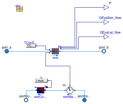
Information
This model can be used to simulate a water-cooled DX cooling coil with single speed compressor.
See Buildings.Fluid.HeatExchangers.DXCoils.UsersGuide for an explanation of the model.
Extends from Buildings.BaseClasses.BaseIcon (Base icon), Buildings.Fluid.HeatExchangers.DXCoils.BaseClasses.EssentialParameters (A partial block for essential parameters).
Parameters
| Type | Name | Default | Description |
|---|---|---|---|
| replaceable package MediumEva | Modelica.Media.Interfaces.Pa... | Medium for evaporator | |
| replaceable package MediumCon | Modelica.Media.Interfaces.Pa... | Medium for condenser | |
| Boolean | computeReevaporation | true | Set to true to compute reevaporation of water that accumulated on coil |
| PartialDXCoil | eva | redeclare Buildings.Fluid.He... | Direct evaporative coil |
| Nominal condition | |||
| PressureDifference | dpEva_nominal | Pressure difference over evaporator at nominal flow rate [Pa] | |
| PressureDifference | dpCon_nominal | Pressure difference over condenser at nominal flow rate [Pa] | |
| Assumptions | |||
| Boolean | allowFlowReversalEva | true | = false to simplify equations, assuming, but not enforcing, no flow reversal for evaporator |
| Boolean | allowFlowReversalCon | true | = false to simplify equations, assuming, but not enforcing, no flow reversal for condenser |
| Flow resistance | |||
| Condenser | |||
| Boolean | from_dpEva | false | = true, use m_flow = f(dp) else dp = f(m_flow) |
| Boolean | linearizeFlowResistanceEva | false | = true, use linear relation between m_flow and dp for any flow rate |
| Real | deltaMEva | 0.1 | Fraction of nominal flow rate where flow transitions to laminar [1] |
| Evaporator | |||
| Boolean | from_dpCon | false | = true, use m_flow = f(dp) else dp = f(m_flow) |
| Boolean | linearizeFlowResistanceCon | false | = true, use linear relation between m_flow and dp for any flow rate |
| Real | deltaMCon | 0.1 | Fraction of nominal flow rate where flow transitions to laminar [1] |
| Dynamics | |||
| Condenser | |||
| Time | tauEva | 60 | Time constant at nominal flow rate (used if energyDynamics <> Modelica.Fluid.Types.Dynamics.SteadyState) [s] |
| Evaporator | |||
| Time | tauCon | 60 | Time constant at nominal flow rate (used if energyDynamics <> Modelica.Fluid.Types.Dynamics.SteadyState) [s] |
| Conservation equations | |||
| Dynamics | energyDynamics | Modelica.Fluid.Types.Dynamic... | Type of energy balance: dynamic (3 initialization options) or steady state |
| Initialization | |||
| Medium 1 | |||
| AbsolutePressure | pEva_start | MediumEva.p_default | Start value of pressure [Pa] |
| Temperature | TEva_start | MediumEva.T_default | Start value of temperature [K] |
| MassFraction | XEva_start[MediumEva.nX] | MediumEva.X_default | Start value of mass fractions m_i/m [kg/kg] |
| ExtraProperty | CEva_start[MediumEva.nC] | fill(0, MediumEva.nC) | Start value of trace substances |
| ExtraProperty | CEva_nominal[MediumEva.nC] | fill(1E-2, MediumEva.nC) | Nominal value of trace substances. (Set to typical order of magnitude.) |
| Medium 2 | |||
| AbsolutePressure | pCon_start | MediumCon.p_default | Start value of pressure [Pa] |
| Temperature | TCon_start | MediumCon.T_default | Start value of temperature [K] |
| MassFraction | XCon_start[MediumCon.nX] | MediumCon.X_default | Start value of mass fractions m_i/m [kg/kg] |
| ExtraProperty | CCon_start[MediumCon.nC] | fill(0, MediumCon.nC) | Start value of trace substances |
| ExtraProperty | CCon_nominal[MediumCon.nC] | fill(1E-2, MediumCon.nC) | Nominal value of trace substances. (Set to typical order of magnitude.) |
| Advanced | |||
| Diagnostics | |||
| Boolean | show_T | false | = true, if actual temperature at port is computed |
Connectors
| Type | Name | Description |
|---|---|---|
| replaceable package MediumEva | Medium for evaporator | |
| replaceable package MediumCon | Medium for condenser | |
| output RealOutput | P | Electrical power consumed by the unit [W] |
| output RealOutput | QEvaSen_flow | Sensible heat flow rate in evaporators [W] |
| output RealOutput | QEvaLat_flow | Latent heat flow rate in evaporators [W] |
| FluidPort_a | port_a | Fluid connector for evaporator inlet (positive design flow direction is from port_a1 to port_b1) |
| FluidPort_b | port_b | Fluid connector b1 (positive design flow direction is from port_a1 to port_b1) |
| FluidPort_a | portCon_a | Fluid connector a of condenser (positive design flow direction is from port_a2 to port_b2) |
| FluidPort_b | portCon_b | Fluid connector b of condenser (positive design flow direction is from port_a2 to port_b2) |
Modelica definition
 Buildings.Fluid.HeatExchangers.DXCoils.BaseClasses.SensibleHeatRatio
Calculates the sensible heat ratio

Information
This block computes the sensible heat ratio.
Extends from Modelica.Blocks.Icons.Block (Basic graphical layout of input/output block).
Parameters
| Type | Name | Default | Description |
|---|---|---|---|
| replaceable package Medium | Modelica.Media.Interfaces.Pa... | Medium model | |
Connectors
| Type | Name | Description |
|---|---|---|
| replaceable package Medium | Medium model | |
| input BooleanInput | on | Set to true to enable compressor, or false to disable compressor |
| input RealInput | p | Pressure at inlet of coil |
| input RealInput | TEvaIn | Temperature of air entering the cooling coil |
| input RealInput | XADP | Humidity mass fraction of air at ADP |
| input RealInput | hADP | Specific enthalpy of air at ADP [J/kg] |
| input RealInput | hEvaIn | Specific enthalpy of air entering the coil |
| output RealOutput | SHR | Sensible Heat Ratio: Ratio of sensible heat load to total heat load |
Modelica definition
 Buildings.Fluid.HeatExchangers.DXCoils.BaseClasses.SpeedSelect
Selects the lower specified speed ratio for multispeed model

Information
This blocks outputs the normalized speed of the compressor, whereas the highest stage is assigned a normalized speed of one, and all other stages are proportional to their actual speed.
Extends from Modelica.Blocks.Icons.Block (Basic graphical layout of input/output block).
Parameters
| Type | Name | Default | Description |
|---|---|---|---|
| Integer | nSta | Number of standard compressor speeds | |
| Real | speSet[nSta] | Array of standard compressor speeds |
Connectors
| Type | Name | Description |
|---|---|---|
| input IntegerInput | stage | Stage of cooling coil (0: off, 1: first stage, 2: second stage...) |
| output RealOutput | speRat | Standard speed ratio |
Modelica definition
 Buildings.Fluid.HeatExchangers.DXCoils.BaseClasses.SpeedShift
Interpolates values between speeds

Information
This block uses the Buildings.Fluid.HeatExchangers.DXCoils.BaseClasses.Functions.speedShift function to interpolate the input array. Depending on input speed ratio and speed set array the input array u is interpolated.
Parameters
| Type | Name | Default | Description |
|---|---|---|---|
| Integer | nSta | Number of standard compressor speeds | |
| AngularVelocity | speSet[nSta] | Compressor speeds [rad/s] | |
| Boolean | variableSpeedCoil | Flag, set to true to interpolate data |
Connectors
| Type | Name | Description |
|---|---|---|
| input RealInput | speRat | Speed ratio |
| input RealInput | u[nSta] | Array to be interpolated |
| output RealOutput | y | Interpolated value |
| input IntegerInput | stage | Stage of coil, or 0/1 for variable-speed coil |
Modelica definition
 Buildings.Fluid.HeatExchangers.DXCoils.BaseClasses.UACp
Calculates UA/Cp of the coil
Information
This model calculates the UA/cp value and the bypass factor of the coil from the nominal inlet and outlet air properties.
For a heat exchanger where one medium changes phase, the NTU-ε relation is
ε = 1 - exp(-NTU) = 1-exp(-UA ⁄ cp ⁄ ṁ).
Since the bypass factor b is defined as b=1-ε, one can write
b = exp(-UA ⁄ cp ⁄ ṁ)
and, hence,
UA ⁄ cp = - ṁ log(b).
Extends from Modelica.Blocks.Icons.Block (Basic graphical layout of input/output block).
Parameters
| Type | Name | Default | Description |
|---|---|---|---|
| replaceable package Medium | Buildings.Media.Air | Medium model | |
| NominalValues | per | redeclare parameter Building... | Performance data |
Connectors
| Type | Name | Description |
|---|---|---|
| replaceable package Medium | Medium model | |
Modelica definition
 Buildings.Fluid.HeatExchangers.DXCoils.BaseClasses.WetCoil
Calculates wet coil condition
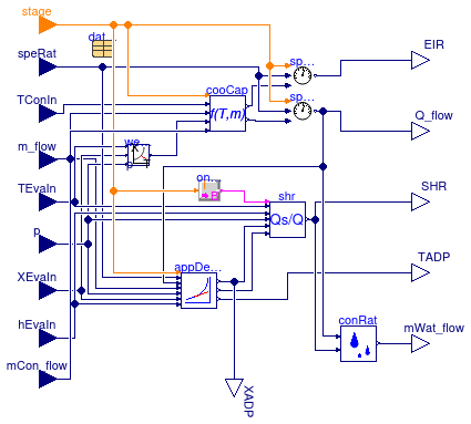
Information
This block calculates the rate of cooling and the coil surface condition under the assumption that the coil is wet.
The dry coil conditions are computed in Buildings.Fluid.HeatExchangers.DXCoils.BaseClasses.DryCoil. See Buildings.Fluid.HeatExchangers.DXCoils.UsersGuide for an explanation of the model.
Extends from Buildings.Fluid.HeatExchangers.DXCoils.BaseClasses.PartialCoilCondition (Partial block for dry and wet coil conditions).
Parameters
| Type | Name | Default | Description |
|---|---|---|---|
| DXCoil | datCoi | redeclare parameter Building... | Performance data |
| Boolean | use_mCon_flow | Set to true to enable connector for the condenser mass flow rate | |
| Boolean | variableSpeedCoil | Flag, set to true for coil with variable speed | |
| CoolingCapacityAirCooled | cooCap | redeclare Buildings.Fluid.He... | Performance data |
| replaceable package Medium | Modelica.Media.Interfaces.Pa... | Medium model | |
Connectors
| Type | Name | Description |
|---|---|---|
| input IntegerInput | stage | Stage of coil, or 0/1 for variable-speed coil |
| input RealInput | speRat | Speed ratio |
| input RealInput | m_flow | Air mass flow rate |
| input RealInput | TEvaIn | Temperature of air entering the cooling coil |
| input RealInput | TConIn | Outside air dry bulb temperature for an air cooled condenser or wetbulb temperature for an evaporative cooled condenser [K] |
| output RealOutput | EIR | Energy Input Ratio |
| output RealOutput | Q_flow | Total cooling capacity [W] |
| input RealInput | mCon_flow | Water mass flow rate at condensers for water-cooled DX units |
| replaceable package Medium | Medium model | |
| output RealOutput | TADP | Dry bulb temperature of air at ADP [K] |
| output RealOutput | SHR | Sensible Heat Ratio: Ratio of sensible heat load to total heat load |
| output RealOutput | mWat_flow | Mass flow rate of water condensed at cooling coil [kg/s] |
| output RealOutput | XADP | Humidity mass fraction of air at apparatus dew point |
| input RealInput | XEvaIn | Inlet air mass fraction |
| input RealInput | p | Pressure at inlet of coil |
| input RealInput | hEvaIn | Specific enthalpy of air entering the coil |
