Package with example models
Information
This package contains examples for the use of models that can be found in
Buildings.Electrical.DC.Lines.
Extends from Modelica.Icons.ExamplesPackage (Icon for packages containing runnable examples).
Package Content
| Name |
Description |
 DCLine DCLine
|
Example model to test the DC lines |
 DCLines DCLines
|
Example model to test the possible combinations between line and load models |
 DCLinesLinearized DCLinesLinearized
|
Example model to test the possible combinations between line and load models |
 RCModel RCModel
|
Example model to test for the DC RC two port model |
 Resistance Resistance
|
Example model to test for the DC resistance two port model |
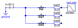
Example model to test the DC lines

Information
This model is a simple test case that show how to use a line model
and parametrize it using a commercial cable.
Extends from Modelica.Icons.Example (Icon for runnable examples).
Modelica definition
model DCLine
extends Modelica.Icons.Example;
Line line(
P_nominal=500,
V_nominal=50,
mode=Types.CableMode.commercial,
commercialCable=
Transmission.LowVoltageCables.PvcAl16(),
l=100) ;
Sources.ConstantVoltage E(V=50) ;
Line line1(
P_nominal=500,
V_nominal=50,
mode=Types.CableMode.commercial,
commercialCable=
Transmission.LowVoltageCables.PvcAl16(),
l=100) ;
Line line2(
P_nominal=500,
V_nominal=50,
mode=Types.CableMode.commercial,
commercialCable=
Transmission.LowVoltageCables.PvcAl16(),
l=100) ;
Modelica.Electrical.Analog.Basic.Ground ground;
Loads.Conductor load1(mode=Types.Load.VariableZ_y_input,
V_nominal=50,
linearized=false,
P_nominal=-50) ;
Loads.Conductor load2(
V_nominal=50,
linearized=false,
P_nominal=-150) ;
Loads.Conductor load3(
V_nominal=50,
linearized=false,
P_nominal=-200) ;
Modelica.Blocks.Sources.Ramp varLoad(
height=0.8,
duration=0.5,
offset=0.2,
startTime=0.3) ;
equation
connect(E.terminal, line.terminal_n);
connect(E.terminal, line1.terminal_n);
connect(E.terminal, line2.terminal_n);
connect(load1.terminal, line.terminal_p);
connect(line1.terminal_p, load2.terminal);
connect(line2.terminal_p, load3.terminal);
connect(varLoad.y, load1.y);
connect(E.n, ground.p);
end DCLine;
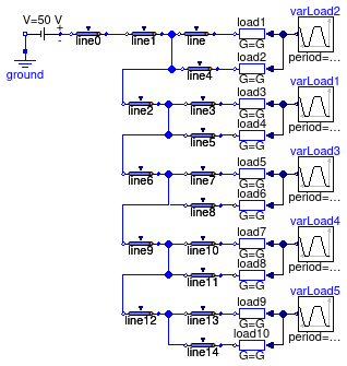
Example model to test the possible combinations between line and load models

Information
This model shows a DC grid with 10 loads and 16 cables.
Each cable is of length l = 10 meters, a parameter that can be modified.
Each load can be either be a full nonlinear model, or be replaced by the
linearized version. The parameter linearLoads = false
can be used to switch between linear and nonlinear implementation.
This model can be used to test how the linearized loads are affected by the voltage drop
caused by the lines. The longer the distance between the load and the source,
the bigger is the voltage drop and thus the error introduced by the linearization.
Extends from Modelica.Icons.Example (Icon for runnable examples).
Parameters
| Type | Name | Default | Description |
|---|
| Boolean | linearLoads | false | Flag that selects between linearized or nonlinear load models |
| Real | L | 10 | Length of each cable |
Modelica definition
model DCLines
extends Modelica.Icons.Example;
parameter Boolean linearLoads = false
;
parameter Real L = 10 ;
Modelica.Units.SI.Power Sloads=load1.S[1] + load2.S[1] + load3.S[1] + load4.S[
1] + load5.S[1] + load6.S[1] + load7.S[1] + load8.S[1] + load9.S[1] +
load10.S[1] ;
Line line(
P_nominal=500,
V_nominal=50,
mode=Types.CableMode.commercial,
commercialCable=
Transmission.LowVoltageCables.PvcAl16(),
l=L,
terminal_n(v(
each start=0))) ;
Sources.ConstantVoltage E(V=50) ;
Line line1(
P_nominal=500,
V_nominal=50,
mode=Types.CableMode.commercial,
commercialCable=
Transmission.LowVoltageCables.PvcAl16(),
l=L) ;
Line line2(
P_nominal=500,
V_nominal=50,
mode=Types.CableMode.commercial,
commercialCable=
Transmission.LowVoltageCables.PvcAl16(),
l=L) ;
Modelica.Electrical.Analog.Basic.Ground ground;
Loads.Conductor load1(mode=Types.Load.VariableZ_y_input,
V_nominal=50,
linearized=linearLoads,
P_nominal=-150) ;
Loads.Conductor load2(
V_nominal=50,
mode=Types.Load.VariableZ_y_input,
linearized=linearLoads,
P_nominal=-120) ;
Loads.Conductor load3(
V_nominal=50,
mode=Types.Load.VariableZ_y_input,
linearized=linearLoads,
P_nominal=-200) ;
Modelica.Blocks.Sources.Trapezoid
varLoad1(
offset=0.4,
amplitude=0.6,
rising=600,
width=1000,
falling=800,
period=3600,
startTime=1800) ;
Loads.Conductor load4(
V_nominal=50,
mode=Types.Load.VariableZ_y_input,
linearized=linearLoads,
P_nominal=-120) ;
Line line3(
P_nominal=500,
V_nominal=50,
mode=Types.CableMode.commercial,
commercialCable=
Transmission.LowVoltageCables.PvcAl16(),
l=L) ;
Line line4(
P_nominal=500,
V_nominal=50,
mode=Types.CableMode.commercial,
commercialCable=
Transmission.LowVoltageCables.PvcAl16(),
l=L) ;
Line line5(
P_nominal=500,
V_nominal=50,
mode=Types.CableMode.commercial,
commercialCable=
Transmission.LowVoltageCables.PvcAl16(),
l=L) ;
Line line0(
P_nominal=500,
V_nominal=50,
mode=Types.CableMode.commercial,
commercialCable=
Transmission.LowVoltageCables.PvcAl16(),
l=L) ;
Modelica.Blocks.Sources.Trapezoid
varLoad2(
startTime=1800,
amplitude=0.8,
rising=400,
width=1300,
falling=900,
period=4000,
offset=0.1) ;
Line line6(
P_nominal=500,
V_nominal=50,
mode=Types.CableMode.commercial,
commercialCable=
Transmission.LowVoltageCables.PvcAl16(),
l=L) ;
Loads.Conductor load5(
V_nominal=50,
mode=Types.Load.VariableZ_y_input,
linearized=linearLoads,
P_nominal=-200) ;
Modelica.Blocks.Sources.Trapezoid
varLoad3(
amplitude=0.7,
rising=660,
width=900,
falling=300,
period=3700,
offset=0.3,
startTime=200) ;
Loads.Conductor load6(
V_nominal=50,
mode=Types.Load.VariableZ_y_input,
linearized=linearLoads,
P_nominal=-120) ;
Line line7(
P_nominal=500,
V_nominal=50,
mode=Types.CableMode.commercial,
commercialCable=
Transmission.LowVoltageCables.PvcAl16(),
l=L) ;
Line line8(
P_nominal=500,
V_nominal=50,
mode=Types.CableMode.commercial,
commercialCable=
Transmission.LowVoltageCables.PvcAl16(),
l=L) ;
Line line9(
P_nominal=500,
V_nominal=50,
mode=Types.CableMode.commercial,
commercialCable=
Transmission.LowVoltageCables.PvcAl16(),
l=L) ;
Loads.Conductor load7(
V_nominal=50,
mode=Types.Load.VariableZ_y_input,
linearized=linearLoads,
P_nominal=-200) ;
Modelica.Blocks.Sources.Trapezoid
varLoad4(
rising=600,
width=1000,
falling=800,
period=3600,
amplitude=0.1,
offset=0.8,
startTime=3300) ;
Loads.Conductor load8(
V_nominal=50,
mode=Types.Load.VariableZ_y_input,
linearized=linearLoads,
P_nominal=-120) ;
Line line10(
P_nominal=500,
V_nominal=50,
mode=Types.CableMode.commercial,
commercialCable=
Transmission.LowVoltageCables.PvcAl16(),
l=L) ;
Line line11(
P_nominal=500,
V_nominal=50,
mode=Types.CableMode.commercial,
commercialCable=
Transmission.LowVoltageCables.PvcAl16(),
l=L) ;
Line line12(
P_nominal=500,
V_nominal=50,
mode=Types.CableMode.commercial,
commercialCable=
Transmission.LowVoltageCables.PvcAl16(),
l=L) ;
Loads.Conductor load9(
V_nominal=50,
mode=Types.Load.VariableZ_y_input,
linearized=linearLoads,
P_nominal=-200) ;
Modelica.Blocks.Sources.Trapezoid
varLoad5(
falling=800,
amplitude=0.5,
rising=800,
width=800,
period=3000,
offset=0.5,
startTime=0) ;
Loads.Conductor load10(
V_nominal=50,
mode=Types.Load.VariableZ_y_input,
linearized=linearLoads,
P_nominal=-120) ;
Line line13(
P_nominal=500,
V_nominal=50,
mode=Types.CableMode.commercial,
commercialCable=
Transmission.LowVoltageCables.PvcAl16(),
l=L) ;
Line line14(
P_nominal=500,
V_nominal=50,
mode=Types.CableMode.commercial,
commercialCable=
Transmission.LowVoltageCables.PvcAl16(),
l=100) ;
equation
connect(load1.terminal, line.terminal_p);
connect(line1.terminal_p, line.terminal_n);
connect(line2.terminal_p, line3.terminal_n);
connect(line3.terminal_p, load3.terminal);
connect(line1.terminal_p, line4.terminal_n);
connect(line4.terminal_p, load2.terminal);
connect(load4.terminal, line5.terminal_p);
connect(line5.terminal_n, line3.terminal_n);
connect(E.terminal, line0.terminal_n);
connect(line0.terminal_p, line1.terminal_n);
connect(varLoad1.y, load3.y);
connect(varLoad1.y, load4.y);
connect(varLoad2.y, load1.y);
connect(varLoad2.y, load2.y);
connect(line6.terminal_p,line7. terminal_n);
connect(line7.terminal_p,load5. terminal);
connect(load6.terminal,line8. terminal_p);
connect(line8.terminal_n,line7. terminal_n);
connect(varLoad3.y,load5. y);
connect(varLoad3.y,load6. y);
connect(line9.terminal_p, line10.terminal_n);
connect(line10.terminal_p, load7.terminal);
connect(load8.terminal, line11.terminal_p);
connect(line11.terminal_n, line10.terminal_n);
connect(varLoad4.y,load7. y);
connect(varLoad4.y,load8. y);
connect(line12.terminal_p, line13.terminal_n);
connect(line13.terminal_p, load9.terminal);
connect(load10.terminal, line14.terminal_p);
connect(line14.terminal_n, line13.terminal_n);
connect(varLoad5.y,load9. y);
connect(varLoad5.y, load10.y);
connect(line2.terminal_n, line4.terminal_n);
connect(line6.terminal_n, line3.terminal_n);
connect(line9.terminal_n, line7.terminal_n);
connect(line12.terminal_n, line10.terminal_n);
connect(E.n, ground.p);
end DCLines;
Example model to test the possible combinations between line and load models

Information
This model is the linearized version of the model
Buildings.Electrical.DC.Lines.Examples.DCLines and
can be used to test how the linearized loads are affected by the voltage drop
caused by the lines. The longer the distance between the load and the source,
the bigger is the voltage drop and thus the error introduced by the linearization.
Extends from Buildings.Electrical.DC.Lines.Examples.DCLines (Example model to test the possible combinations between line and load models).
Parameters
| Type | Name | Default | Description |
|---|
| Boolean | linearLoads | true | Flag that selects between linearized or nonlinear load models |
| Real | L | 10 | Length of each cable |
Modelica definition
Example model to test for the DC RC two port model

Information
This model shows how to use a two port resistance-capacitance model.
The example also shows a comparison between the dynamic and steady state version model
that can be selected by changing the boolean flag use_C.
In this example the RC connects an ideal constant voltage source with
a short circuit. The steady state current value passing through the RC
model depends just on the value of R.
The RC model implement a T-model to represent the electric connection between the
two connectors (see
Buildings.Electrical.DC.Lines.TwoPortRCLine for more details).
The capacitance C see an equivalent Thevenin's resistance that is equal to
REQ = 0.5 R and thus the time constant associated to the capacitance is
τ = REQ C = 0.5 R C = 2 seconds,
thus the duration of transient period is about 10 seconds.
Extends from Modelica.Icons.Example (Icon for runnable examples).
Modelica definition
model RCModel
extends Modelica.Icons.Example;
TwoPortRCLine RC_ss(
C=1,
V_nominal=50,
R=8) ;
Sources.ConstantVoltage constantVoltage(V=50) ;
Modelica.Electrical.Analog.Basic.Ground ground;
Loads.Resistor sc_ss(V_nominal=50, R=0) ;
Sensors.GeneralizedSensor sen_ss ;
TwoPortRCLine RC_dyn(
C=1,
V_nominal=50,
use_C=true,
R=8) ;
Loads.Resistor sc_dyn(V_nominal=50, R=0) ;
Sensors.GeneralizedSensor sen_dyn ;
equation
connect(ground.p, constantVoltage.n);
connect(constantVoltage.terminal, RC_ss.terminal_n);
connect(RC_ss.terminal_p, sen_ss.terminal_n);
connect(sen_ss.terminal_p, sc_ss.terminal);
connect(RC_dyn.terminal_p, sen_dyn.terminal_n);
connect(sen_dyn.terminal_p, sc_dyn.terminal);
connect(constantVoltage.terminal, RC_dyn.terminal_n);
end RCModel;
Example model to test for the DC resistance two port model

Information
This model shows how to use a two port resistance.
In this example the resistance connects an ideal constant voltage source with
a short circuit. The current flowing through the circuit depends just
on the value of the two port resistance.
Extends from Modelica.Icons.Example (Icon for runnable examples).
Modelica definition
 Buildings.Electrical.DC.Lines.Examples.DCLine
 Buildings.Electrical.DC.Lines.Examples.DCLines
 Buildings.Electrical.DC.Lines.Examples.DCLinesLinearized
 Buildings.Electrical.DC.Lines.Examples.RCModel
 Buildings.Electrical.DC.Lines.Examples.Resistance
