Buildings.Controls.OBC.ASHRAE.G36_PR1.AHUs.MultiZone.VAV.SetPoints
Output setpoints for AHU control
Information
This package contains sequences generating setpoints for VAV AHU control.
Package Content
| Name | Description |
|---|---|
| Control of actuated exhaust air dampers without fans | |
| Return fan control with direct building pressure control | |
| Block to control multi zone VAV AHU supply fan | |
| Multizone VAV AHU coil valve positions | |
| Supply air temperature setpoint for multi zone system | |
| Package of sequences for calculating minimum outdoor airflow rate | |
| Collection of validation models |
 Buildings.Controls.OBC.ASHRAE.G36_PR1.AHUs.MultiZone.VAV.SetPoints.ExhaustDamper
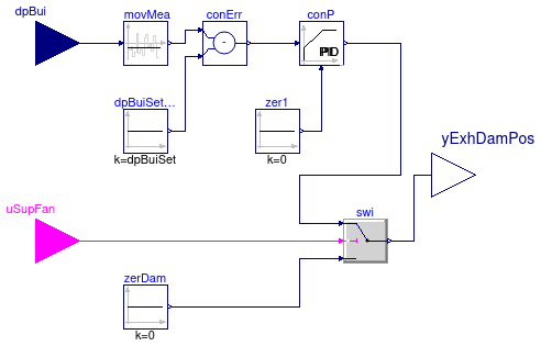
Control of actuated exhaust air dampers without fans
Information
Control sequence for actuated exhaust damper yExhDamPos
without fans. It is implemented according to ASHRAE Guidline 36 (G36), PART 5.N.8.
(for multi zone VAV AHU), PART 5.P.6 and PART3.2B.3 (for single zone VAV AHU).
Multi zone VAV AHU: Control of actuated exhaust dampers without fans (PART 5.N.8)
- The exhaust damper is enabled when the associated supply fan is proven on
uSupFan = true, and disabled otherwise. - When enabled, a P-only control loop modulates the exhaust damper to maintain
a building static pressure of
dpBui, which is by default 12 Pa (0.05 inchWC). -
When
uSupFan = false, the damper is closed.
Parameters
| Type | Name | Default | Description |
|---|---|---|---|
| Real | dpBuiSet | 12 | Building static pressure difference relative to ambient (positive to pressurize the building) [Pa] |
| Exhaust damper P-control parameter | |||
| Real | k | 0.5 | Gain, applied to building pressure control error normalized with dpBuiSet [1] |
Connectors
| Type | Name | Description |
|---|---|---|
| input RealInput | dpBui | Building static pressure difference, relative to ambient (positive if pressurized) [Pa] |
| input BooleanInput | uSupFan | Supply fan status |
| output RealOutput | yExhDamPos | Exhaust damper control signal (0: closed, 1: open) [1] |
Modelica definition
 Buildings.Controls.OBC.ASHRAE.G36_PR1.AHUs.MultiZone.VAV.SetPoints.ReturnFanDirectPressure
Return fan control with direct building pressure control
Information
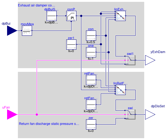
Setpoint for return fan discharge pressure and exhaust air damper for a multi zone VAV AHU according to ASHRAE guideline G36, PART 5.N.10 (return fan control with direct building pressure).
-
Return fan operates whenever associated supply fan is proven on and is off otherwise.
-
Return fan is controlled to maintain return fan discharge static pressure at setpoint
dpBuiSet. -
Exhaust damper is only enabled when the associated supply and return fans are proven on (
uFan=true) and the minimum outdoor air damper is open (to be controlled in a separate sequence). The exhaust dampers is closed when the fan is disabled. -
The building static pressure is time averaged with a sliding 5-minute window to dampen fluctuations. The averaged value shall be displayed and is used for control.
-
When the exhaust damper is enabled, a control loop modulates the exhaust damper in sequence with the return fan static pressure setpoint as shown in the figure below to maintain the building pressure equal to
dpBuiSet, which is by default 12 Pa (0.05 inches).
The output signal of the building pressure control is as follows:
-
From 0 to 0.5, the building pressure control loop modulates the exhaust
dampers from
yExhDam = 0(closed) toyExhDam = 1(open). -
From 0.5 to 1, the building pressure control loop resets the return fan
discharge static pressure setpoint from
dpDisMintodpDisMax. ThedpDisMinanddpDisMaxare specified in Section G36 PART 3.2A.3.b.

Parameters
| Type | Name | Default | Description |
|---|---|---|---|
| Real | dpBuiSet | 12 | Building static pressure difference relative to ambient (positive to pressurize the building) [Pa] |
| Real | dpDisMin | 2.4 | Minimum return fan discharge static pressure difference setpoint [Pa] |
| Real | dpDisMax | 40 | Maximum return fan discharge static pressure setpoint [Pa] |
| Real | k | 1 | Gain, normalized using dpBuiSet [1] |
Connectors
| Type | Name | Description |
|---|---|---|
| input RealInput | dpBui | Building static pressure difference, relative to ambient (positive if pressurized) [Pa] |
| input BooleanInput | uFan | Fan on/off signal, true if fan is on |
| output RealOutput | dpDisSet | Return fan discharge static pressure setpoint [Pa] |
| output RealOutput | yExhDam | Exhaust damper control signal (0: closed, 1: open) [1] |
Modelica definition
 Buildings.Controls.OBC.ASHRAE.G36_PR1.AHUs.MultiZone.VAV.SetPoints.SupplyFan
Block to control multi zone VAV AHU supply fan
Information
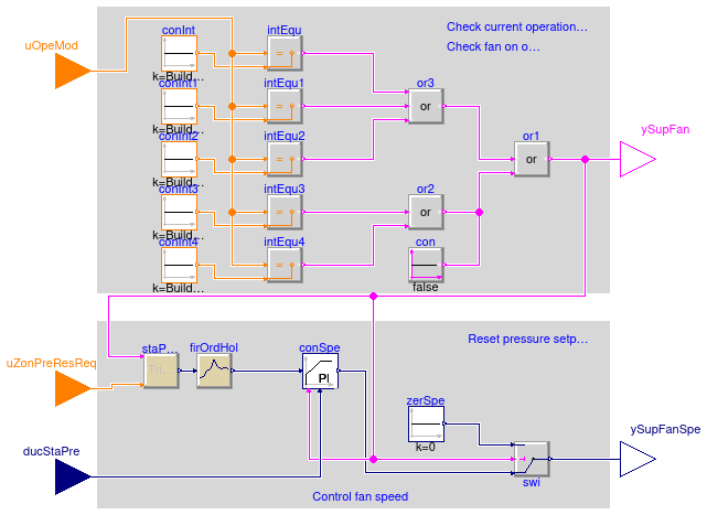
Supply fan control for a multi zone VAV AHU according to ASHRAE guideline G36, PART 5.N.1 (Supply fan control).
Supply fan start/stop
- Supply fan shall run when system is in the Cool-down, Setup, or Occupied mode
- If there are any VAV-reheat boxes on perimeter zones, supply fan shall also run when system is in Setback or Warmup mode;
- If the AHU does not serve dual duct boxes
that do not have hot-duct inlet airflow sensors (
have_duaDucBox=true) or the AHU does not have airflow measurement station (have_airFloMeaSta=false), sum the current airflow rate from the VAV boxes and output to a software point.
Static pressure setpoint reset
Static pressure setpoint shall be reset using trim-respond logic using following parameters as a starting point:
| Variable | Value | Definition |
|---|---|---|
| Device | AHU Supply Fan | Associated device |
| SP0 | iniSet | Initial setpoint |
| SPmin | minSet | Minimum setpoint |
| SPmax | maxSet | Maximum setpoint |
| Td | delTim | Delay timer |
| T | samplePeriod | Time step |
| I | numIgnReq | Number of ignored requests |
| R | uZonPreResReq | Number of requests |
| SPtrim | triAmo | Trim amount |
| SPres | resAmo | Respond amount |
| SPres_max | maxRes | Maximum response per time interval |
Static pressure control
Supply fan speed is controlled with a PI controller to maintain duct static pressure at setpoint
when the fan is proven on. The setpoint for the PI controller and the measured
duct static pressure are normalized with the maximum design static presssure
maxSet.
Where the zone groups served by the system are small,
provide multiple sets of gains that are used in the control loop as a function
of a load indicator (such as supply fan airflow rate, the area of the zone groups
that are occupied, etc.).
Parameters
| Type | Name | Default | Description |
|---|---|---|---|
| System configuration | |||
| Boolean | have_perZonRehBox | false | Check if there is any VAV-reheat boxes on perimeter zones |
| Boolean | have_duaDucBox | false | Check if the AHU serves dual duct boxes |
| Boolean | have_airFloMeaSta | false | Check if the AHU has AFMS (Airflow measurement station) |
| Trim and respond for pressure setpoint | |||
| Real | iniSet | 120 | Initial setpoint [Pa] |
| Real | minSet | 25 | Minimum setpoint [Pa] |
| Real | maxSet | Maximum setpoint [Pa] | |
| Real | delTim | 600 | Delay time after which trim and respond is activated [s] |
| Real | samplePeriod | 120 | Sample period [s] |
| Integer | numIgnReq | 2 | Number of ignored requests |
| Real | triAmo | -12.0 | Trim amount [Pa] |
| Real | resAmo | 15 | Respond amount (must be opposite in to triAmo) [Pa] |
| Real | maxRes | 32 | Maximum response per time interval (same sign as resAmo) [Pa] |
| Fan PID controller | |||
| SimpleController | controllerType | Buildings.Controls.OBC.CDL.T... | Type of controller |
| Real | k | 0.1 | Gain of controller, normalized using maxSet [1] |
| Real | Ti | 60 | Time constant of integrator block [s] |
| Real | Td | 0.1 | Time constant of derivative block [s] |
| Real | yFanMax | 1 | Maximum allowed fan speed [1] |
| Real | yFanMin | 0.1 | Lowest allowed fan speed if fan is on [1] |
Connectors
| Type | Name | Description |
|---|---|---|
| input IntegerInput | uOpeMod | System operation mode |
| input RealInput | ducStaPre | Measured duct static pressure [Pa] |
| input IntegerInput | uZonPreResReq | Zone static pressure reset requests |
| output BooleanOutput | ySupFan | Supply fan on status |
| output RealOutput | ySupFanSpe | Supply fan speed [1] |
Modelica definition
 Buildings.Controls.OBC.ASHRAE.G36_PR1.AHUs.MultiZone.VAV.SetPoints.SupplySignals
Multizone VAV AHU coil valve positions
Information
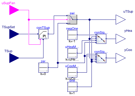
Block that outputs the supply temperature control loop signal, and the coil valve postions for VAV system with multiple zones, implemented according to the ASHRAE Guideline G36, PART 5.N.2 (Supply air temperature control).
The supply air temperature control loop signal uTSup
is computed using a PI controller that tracks the supply air temperature
setpoint TSupSet.
If the fan is off, then uTSup = 0.
Heating valve control signal (or modulating electric heating
coil if applicable) yHea and cooling valve control signal yCoo
are sequenced based on the supply air temperature control loop signal uTSup.
From uTSup = uHeaMax to uTSup = -1,
yHea increases linearly from 0 to 1.
Similarly, uTSup = uCooMin to uTSup = +1,
yCoo increases linearly from 0 to 1.
The output uTSup can be used in a controller for the economizer.
Parameters
| Type | Name | Default | Description |
|---|---|---|---|
| SimpleController | controllerType | Buildings.Controls.OBC.CDL.T... | Type of controller for supply air temperature signal |
| Real | kTSup | 0.05 | Gain of controller for supply air temperature signal |
| Real | TiTSup | 600 | Time constant of integrator block for supply temperature control signal [s] |
| Real | TdTSup | 0.1 | Time constant of derivative block for supply temperature control signal [s] |
| Real | uHeaMax | -0.25 | Upper limit of controller signal when heating coil is off. Require -1 < uHeaMax < uCooMin < 1. [1] |
| Real | uCooMin | 0.25 | Lower limit of controller signal when cooling coil is off. Require -1 < uHeaMax < uCooMin < 1. [1] |
Connectors
| Type | Name | Description |
|---|---|---|
| input RealInput | TSup | Measured supply air temperature [K] |
| input RealInput | TSupSet | Setpoint for supply air temperature [K] |
| input BooleanInput | uSupFan | Supply fan status |
| output RealOutput | yHea | Control signal for heating [1] |
| output RealOutput | yCoo | Control signal for cooling [1] |
| output RealOutput | uTSup | Supply temperature control signal [1] |
Modelica definition
 Buildings.Controls.OBC.ASHRAE.G36_PR1.AHUs.MultiZone.VAV.SetPoints.SupplyTemperature
Supply air temperature setpoint for multi zone system
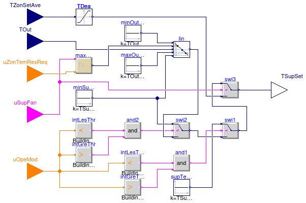
Information
Block that outputs the supply air temperature setpoint and the coil valve control inputs for VAV system with multiple zones, implemented according to the ASHRAE Guideline G36, PART 5.N.2 (Supply air temperature control).
The control loop is enabled when the supply air fan uSupFan is proven on,
and disabled and the output set to Deadband otherwise.
The supply air temperature setpoint is computed as follows.
Setpoints for TSupSetMin, TSupSetMax,
TSupSetDes, TOutMin, TOutMax
The default range of outdoor air temperature (TOutMin=16°C,
TOutMax=21°C) used to reset the occupied mode TSupSet
was chosen to maximize economizer hours. It may be preferable to use a lower
range of outdoor air temperature (e.g. TOutMin=13°C,
TOutMax=18°C) to minimize fan energy.
The TSupSetMin variable is used during warm weather when little reheat
is expected to minimize fan energy. It should not be set too low or it may cause
excessive chilled water temperature reset requests which will reduce chiller
plant efficiency. It should be set no lower than the design coil leaving air
temperature.
The TSupSetMax variable is typically 18 °C in mild and dry climate,
16 °C or lower in humid climates. It should not typically be greater than
18 °C since this may lead to excessive fan energy that can offset the mechanical
cooling savings from economizer operation.
During occupied mode (uOpeMod=1)
The TSupSet shall be reset from TSupSetMin when the outdoor
air temperature is TOutMax and above, proportionally up to
maximum supply temperature when the outdoor air temperature is TOutMin and
below. The maximum supply temperature shall be reset using trim and respond logic between
TSupSetDes and TSupSetMax. Parameters suggested for the
trim and respond logic are shown in the table below. They require adjustment
during the commissioning and tuning phase.
| Variable | Value | Definition |
|---|---|---|
| Device | AHU Supply Fan | Associated device |
| SP0 | iniSet | Initial setpoint |
| SPmin | TSupSetDes | Minimum setpoint |
| SPmax | TSupSetMax | Maximum setpoint |
| Td | delTim | Delay timer |
| T | samplePeriod | Time step |
| I | numIgnReq | Number of ignored requests |
| R | uZonTemResReq | Number of requests |
| SPtrim | triAmo | Trim amount |
| SPres | resAmo | Respond amount |
| SPres_max | maxRes | Maximum response per time interval |

During Setup and Cool-down modes (uOpeMod=2, uOpeMod=3)
Supply air temperature setpoint TSupSet shall be TSupSetMin.
During Setback and Warmup modes (uOpeMod=4, uOpeMod=5)
Supply air temperature setpoint TSupSet shall be TSupWarUpSetBac.
Valves control
Supply air temperature shall be controlled to setpoint using a control loop whose output is mapped to sequence the hot water valve or modulating electric heating coil (if applicable) or chilled water valves.
Parameters
| Type | Name | Default | Description |
|---|---|---|---|
| Temperatures | |||
| Real | TSupSetDes | 285.15 | Design coil leaving air temperature [K] |
| Real | TSupSetMin | 285.15 | Lowest cooling supply air temperature setpoint when the outdoor air temperature is at the higher value of the reset range and above. This should not be lower than the design coil leaving air temperature [K] |
| Real | TSupSetMax | 291.15 | Highest cooling supply air temperature setpoint. It is typically 18 degC (65 degF) in mild and dry climates, 16 degC (60 degF) or lower in humid climates [K] |
| Real | TOutMin | 289.15 | Lower value of the outdoor air temperature reset range. Typically value is 16 degC (60 degF) [K] |
| Real | TOutMax | 294.15 | Higher value of the outdoor air temperature reset range. Typically value is 21 degC (70 degF) [K] |
| Real | TSupWarUpSetBac | 308.15 | Supply temperature in warm up and set back mode [K] |
| Trim and respond logic | |||
| Real | delTim | 600 | Delay timer [s] |
| Real | samplePeriod | 120 | Sample period of component [s] |
| Integer | numIgnReq | 2 | Number of ignorable requests for TrimResponse logic |
| Real | triAmo | 0.1 | Trim amount [K] |
| Real | resAmo | -0.2 | Response amount [K] |
| Real | maxRes | -0.6 | Maximum response per time interval [K] |
Connectors
| Type | Name | Description |
|---|---|---|
| input RealInput | TOut | Outdoor air temperature [K] |
| input RealInput | TZonSetAve | Average of heating and cooling setpoint [K] |
| input BooleanInput | uSupFan | Supply fan status |
| input IntegerInput | uOpeMod | System operation mode |
| input IntegerInput | uZonTemResReq | Zone cooling supply air temperature reset request |
| output RealOutput | TSupSet | Setpoint for supply air temperature [K] |