Subsequences for economizer control
Information
This package contains subsequences for multi zone VAV AHU economizer control.
Package Content
| Name |
Description |
 Enable Enable
|
Multi zone VAV AHU economizer enable/disable switch |
 Limits Limits
|
Multi zone VAV AHU minimum outdoor air control - damper position limits |
 Modulation Modulation
|
Outdoor and return air damper position modulation sequence for multi zone VAV AHU |
 Validation Validation
|
Collection of validation models |
Multi zone VAV AHU economizer enable/disable switch
Information
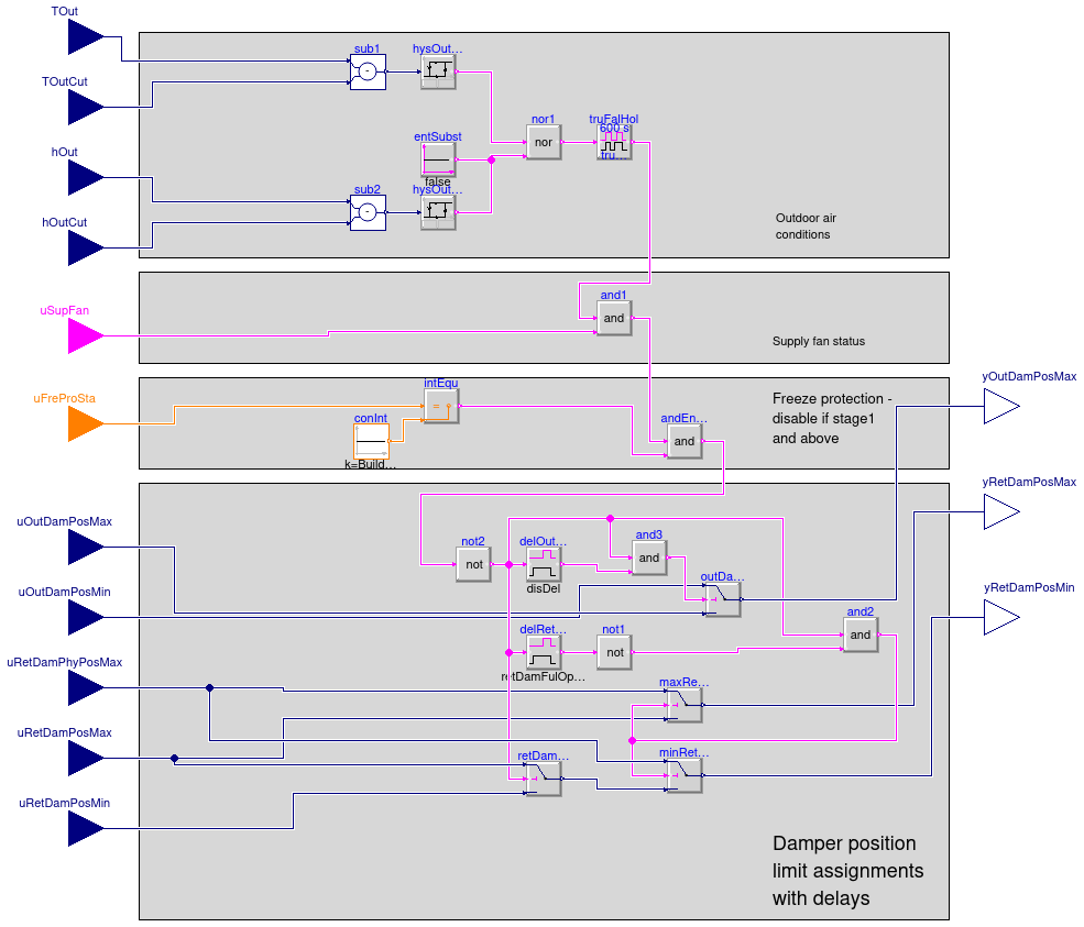
This is a multi zone VAV AHU economizer enable/disable sequence
based on ASHRAE G36 PART 5.N.7 and PART 5.A.17. Additional
conditions included in the sequence are: freeze protection (freeze protection
stage 0-3, see PART 5.N.12), supply fan status (on or off, see PART 5.N.5).
The economizer is disabled whenever the outdoor air conditions
exceed the economizer high limit setpoint.
This sequence allows for all device types listed in
ASHRAE 90.1-2013 and Title 24-2013.
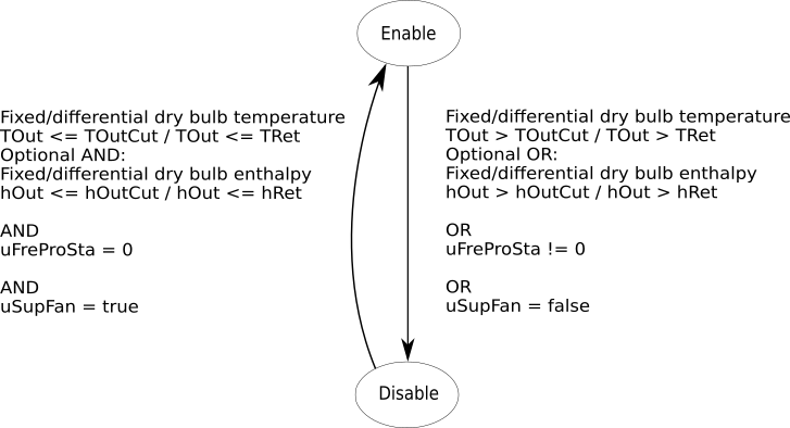
In addition, the economizer gets disabled without a delay whenever any of the
following is true:
The following state machine chart illustrates the transitions between enabling and disabling:
After the disable signal is activated, the following procedure is applied, per PART 5.N.7.d, in order to
prevent pressure fluctuations in the HVAC system:
-
The return damper gets fully opened (
yRetDamPosMax = uRetDamPhyPosMax and
yRetDamPosMin = uRetDamPhyPosMax) for retDamFulOpeTim
time period, after which the return damper gets released to its minimum outdoor airflow control position
(yRetDamPosMax = uRetDamPosMax and yRetDamPosMin = uRetDamPosMax).
-
The outdoor air damper is closed to its minimum outoor airflow control limit (
yOutDamPosMax = uOutDamPosMin)
after a disDel time delay.
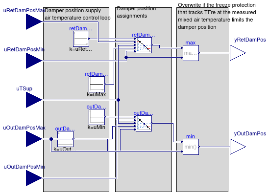
This sequence also has an overwrite of the damper positions to track
a minimum mixed air temperature of TFreSet, which is
by default set to 4°C (39.2 F).
This is implemented using a proportional controller with a default deadband of
1 K, which can be adjusted using the parameter kPFrePro.
Parameters
| Type | Name | Default | Description |
|---|
| Conditional |
| Boolean | use_enthalpy | true | Set to true to evaluate outdoor air enthalpy in addition to temperature |
| Advanced |
| Hysteresis |
| Real | delTOutHis | 1 | Delta between the temperature hysteresis high and low limit [K] |
| Real | delEntHis | 1000 | Delta between the enthalpy hysteresis high and low limits [J/kg] |
| Delays at disable |
| Real | retDamFulOpeTim | 180 | Time period to keep RA damper fully open before releasing it for minimum outdoor airflow control
at disable to avoid pressure fluctuations [s] |
| Real | disDel | 15 | Short time delay before closing the OA damper at disable to avoid pressure fluctuations [s] |
Connectors
| Type | Name | Description |
|---|
| input RealInput | TOut | Outdoor air temperature [K] |
| input RealInput | hOut | Outdoor air enthalpy [J/kg] |
| input RealInput | TOutCut | OA temperature high limit cutoff. For differential dry bulb temeprature condition use return air temperature measurement [K] |
| input RealInput | hOutCut | OA enthalpy high limit cutoff. For differential enthalpy use return air enthalpy measurement [J/kg] |
| input RealInput | uOutDamPosMin | Minimum outdoor air damper position, output from damper position limits sequence [1] |
| input RealInput | uOutDamPosMax | Maximum outdoor air damper position, output from damper position limits sequence [1] |
| input RealInput | uRetDamPosMax | Maximum return air damper position, output from damper position limits sequence [1] |
| input RealInput | uRetDamPosMin | Minimum return air damper position, output from damper position limits sequence [1] |
| input RealInput | uRetDamPhyPosMax | Physical maximum return air damper position, output from damper position limits sequence [1] |
| input BooleanInput | uSupFan | Supply fan on/off status signal |
| input IntegerInput | uFreProSta | Freeze protection stage status signal |
| output RealOutput | yOutDamPosMax | Maximum outdoor air damper position [1] |
| output RealOutput | yRetDamPosMin | Minimum return air damper position [1] |
| output RealOutput | yRetDamPosMax | Maximum return air damper position [1] |
Modelica definition
block Enable
parameter Boolean use_enthalpy = true
;
parameter Real delTOutHis(
final unit="K",
final displayUnit="K",
final quantity="TemperatureDifference")=1
;
parameter Real delEntHis(
final unit="J/kg",
final quantity="SpecificEnergy")=1000
;
parameter Real retDamFulOpeTim(
final unit="s",
final quantity="Time")=180
;
parameter Real disDel(
final unit="s",
final quantity="Time")=15
;
Buildings.Controls.OBC.CDL.Interfaces.RealInput TOut(
final unit="K",
final displayUnit="degC",
final quantity = "ThermodynamicTemperature")
;
Buildings.Controls.OBC.CDL.Interfaces.RealInput hOut(
final unit="J/kg",
final quantity="SpecificEnergy")
if use_enthalpy
;
Buildings.Controls.OBC.CDL.Interfaces.RealInput TOutCut(
final unit="K",
final displayUnit="degC",
final quantity = "ThermodynamicTemperature")
;
Buildings.Controls.OBC.CDL.Interfaces.RealInput hOutCut(
final unit="J/kg",
final quantity="SpecificEnergy")
if use_enthalpy
;
Buildings.Controls.OBC.CDL.Interfaces.RealInput uOutDamPosMin(
final unit="1",
final min=0,
final max=1)
;
Buildings.Controls.OBC.CDL.Interfaces.RealInput uOutDamPosMax(
final unit="1",
final min=0,
final max=1)
;
Buildings.Controls.OBC.CDL.Interfaces.RealInput uRetDamPosMax(
final unit="1",
final min=0,
final max=1)
;
Buildings.Controls.OBC.CDL.Interfaces.RealInput uRetDamPosMin(
final unit="1",
final min=0,
final max=1)
;
Buildings.Controls.OBC.CDL.Interfaces.RealInput uRetDamPhyPosMax(
final unit="1",
final min=0,
final max=1)
;
Buildings.Controls.OBC.CDL.Interfaces.BooleanInput uSupFan
;
Buildings.Controls.OBC.CDL.Interfaces.IntegerInput uFreProSta ;
Buildings.Controls.OBC.CDL.Interfaces.RealOutput yOutDamPosMax(
final unit="1",
final min=0,
final max=1) ;
Buildings.Controls.OBC.CDL.Interfaces.RealOutput yRetDamPosMin(
final unit="1",
final min=0,
final max=1) ;
Buildings.Controls.OBC.CDL.Interfaces.RealOutput yRetDamPosMax(
final unit="1",
final min=0,
final max=1) ;
Buildings.Controls.OBC.CDL.Logical.TrueFalseHold truFalHol(
trueHoldDuration=600) ;
Buildings.Controls.OBC.CDL.Logical.And andEnaDis
;
protected
final parameter Real TOutHigLimCutHig(
final unit="K",
final displayUnit="K",
final quantity="TemperatureDifference")= 0
;
final parameter Real TOutHigLimCutLow = TOutHigLimCutHig - delTOutHis
;
final parameter Real hOutHigLimCutHig(
final unit="J/kg",
final quantity="SpecificEnergy")= 0
;
final parameter Real hOutHigLimCutLow = hOutHigLimCutHig - delEntHis
;
Buildings.Controls.OBC.CDL.Logical.Sources.Constant entSubst(
final k=false)
if not use_enthalpy
;
Buildings.Controls.OBC.CDL.Continuous.Subtract sub2
if use_enthalpy ;
Buildings.Controls.OBC.CDL.Continuous.Subtract sub1
;
Buildings.Controls.OBC.CDL.Continuous.Hysteresis hysOutTem(
final uLow=TOutHigLimCutLow,
final uHigh=TOutHigLimCutHig)
;
Buildings.Controls.OBC.CDL.Continuous.Hysteresis hysOutEnt(
final uLow=hOutHigLimCutLow,
final uHigh=hOutHigLimCutHig)
if use_enthalpy
;
Buildings.Controls.OBC.CDL.Continuous.Switch outDamSwitch
;
Buildings.Controls.OBC.CDL.Continuous.Switch retDamSwitch ;
Buildings.Controls.OBC.CDL.Continuous.Switch maxRetDamSwitch
;
Buildings.Controls.OBC.CDL.Continuous.Switch minRetDamSwitch
;
Buildings.Controls.OBC.CDL.Logical.Nor nor1 ;
Buildings.Controls.OBC.CDL.Logical.Not not2 ;
Buildings.Controls.OBC.CDL.Logical.And and2 ;
Buildings.Controls.OBC.CDL.Logical.And and1 ;
Buildings.Controls.OBC.CDL.Logical.And and3 ;
Buildings.Controls.OBC.CDL.Integers.Equal intEqu
;
Buildings.Controls.OBC.CDL.Logical.TrueDelay delOutDamOsc(
final delayTime=disDel)
;
Buildings.Controls.OBC.CDL.Logical.TrueDelay delRetDam(
final delayTime=retDamFulOpeTim)
;
Buildings.Controls.OBC.CDL.Logical.Not not1 ;
Buildings.Controls.OBC.CDL.Integers.Sources.Constant conInt(
final k=Buildings.Controls.OBC.ASHRAE.G36_PR1.Types.FreezeProtectionStages.stage0)
;
equation
connect(TOut, sub1.u1);
connect(TOutCut, sub1.u2);
connect(sub1.y, hysOutTem.u);
connect(hOut, sub2.u1);
connect(hOutCut, sub2.u2);
connect(sub2.y, hysOutEnt.u);
connect(hysOutTem.y, nor1.u1);
connect(hysOutEnt.y, nor1.u2);
connect(entSubst.y, nor1.u2);
connect(uOutDamPosMin, outDamSwitch.u1);
connect(uOutDamPosMax, outDamSwitch.u3);
connect(uRetDamPhyPosMax, maxRetDamSwitch.u1);
connect(uRetDamPosMax, maxRetDamSwitch.u3);
connect(nor1.y, truFalHol.u);
connect(andEnaDis.y, not2.u);
connect(maxRetDamSwitch.y, yRetDamPosMax);
connect(and2.y, maxRetDamSwitch.u2);
connect(and2.y, minRetDamSwitch.u2);
connect(not2.y, retDamSwitch.u2);
connect(uRetDamPosMax, retDamSwitch.u1);
connect(uRetDamPosMin, retDamSwitch.u3);
connect(retDamSwitch.y, minRetDamSwitch.u3);
connect(uRetDamPhyPosMax, minRetDamSwitch.u1);
connect(truFalHol.y, and1.u1);
connect(and1.y, andEnaDis.u1);
connect(uSupFan, and1.u2);
connect(outDamSwitch.u2, and3.y);
connect(not2.y, and3.u1);
connect(and2.u1, not2.y);
connect(and3.u2, delOutDamOsc.y);
connect(delOutDamOsc.u, not2.y);
connect(not2.y, delRetDam.u);
connect(delRetDam.y, not1.u);
connect(not1.y, and2.u2);
connect(uFreProSta, intEqu.u1);
connect(conInt.y, intEqu.u2);
connect(intEqu.y, andEnaDis.u2);
connect(outDamSwitch.y, yOutDamPosMax);
connect(minRetDamSwitch.y, yRetDamPosMin);
end Enable;
Multi zone VAV AHU minimum outdoor air control - damper position limits
Information
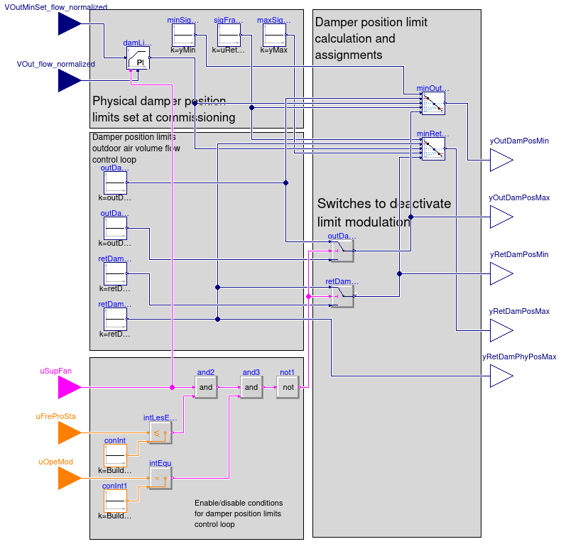
This block models the multi zone VAV AHU minimum outdoor air control with a single
common damper for minimum outdoor air and economizer functions based on outdoor airflow
measurement, designed in line with ASHRAE Guidline 36 (G36), PART 5.N.6.c.
The controller is enabled when the supply fan is proven on (uSupFan=true),
the AHU operation mode
Buildings.Controls.OBC.ASHRAE.G36_PR1.Types.OperationModes equals occupied,
and the freeze protection stage
Buildings.Controls.OBC.ASHRAE.G36_PR1.Types.FreezeProtectionStages is stage1 or lower.
Otherwise the damper position limits are set to their corresponding maximum and minimum physical or at
commissioning fixed limits. The state machine chart below illustrates listed conditions:

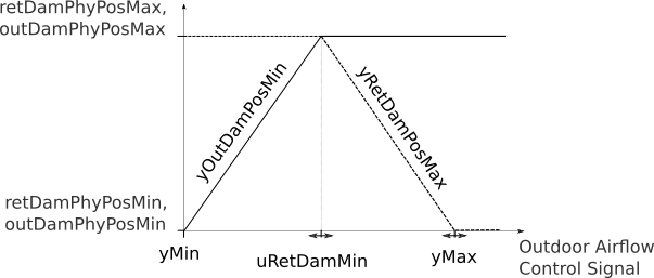
The controller sets the outdoor and return damper position limits so
that the outdoor airflow rate VOut_flow stays equal or above the
minimum outdoor air setpoint VOutMinSet_flow. The fraction of the controller
output signal between yMin and uRetDamMin is
linearly mapped to the outdoor air damper minimal position yOutDamPosMin
while the fraction of the controller output between uRetDamMin and
yMax is linearly mapped to the return air damper maximum position
yRetDamPosMax. Thus the dampers are not interlocked.
The following control charts show the input/output structure and an expected damper position
limits for a well configured controller.
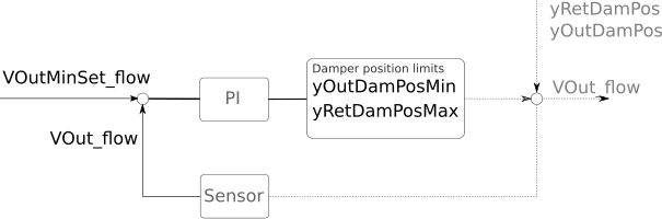
The expected damper position limits vs. the control loop signal are as follows:
Parameters
| Type | Name | Default | Description |
|---|
| Controller |
| SimpleController | controllerType | Buildings.Controls.OBC.CDL.T... | Type of controller |
| Real | k | 0.05 | Gain of damper limit controller [1] |
| Real | Ti | 120 | Time constant of damper limit controller integrator block [s] |
| Real | Td | 0.1 | Time constant of damper limit controller derivative block [s] |
| Commissioning |
| Controller |
| Real | uRetDamMin | 0.5 | Loop signal value to start decreasing the maximum return air damper position [1] |
| Physical damper position limits |
| Real | retDamPhyPosMax | 1 | Physically fixed maximum position of the return air damper [1] |
| Real | retDamPhyPosMin | 0 | Physically fixed minimum position of the return air damper [1] |
| Real | outDamPhyPosMax | 1 | Physically fixed maximum position of the outdoor air damper [1] |
| Real | outDamPhyPosMin | 0 | Physically fixed minimum position of the outdoor air damper [1] |
Connectors
| Type | Name | Description |
|---|
| input RealInput | VOut_flow_normalized | Measured outdoor volumetric airflow rate, normalized by design minimum outdoor airflow rate [1] |
| input RealInput | VOutMinSet_flow_normalized | Effective minimum outdoor airflow setpoint, normalized by design minimum outdoor airflow rate [1] |
| input IntegerInput | uOpeMod | AHU operation mode status signal |
| input IntegerInput | uFreProSta | Freeze protection status signal |
| input BooleanInput | uSupFan | Supply fan status signal |
| output RealOutput | yOutDamPosMin | Minimum outdoor air damper position limit [1] |
| output RealOutput | yOutDamPosMax | Maximum outdoor air damper position limit [1] |
| output RealOutput | yRetDamPosMin | Minimum return air damper position limit [1] |
| output RealOutput | yRetDamPosMax | Maximum return air damper position limit [1] |
| output RealOutput | yRetDamPhyPosMax | Physical maximum return air damper position limit. Required as an input for the economizer enable disable sequence [1] |
Modelica definition
block Limits
parameter Real uRetDamMin(
final min=yMin,
final max=yMax,
final unit="1") = 0.5
;
parameter Buildings.Controls.OBC.CDL.Types.SimpleController controllerType=
Buildings.Controls.OBC.CDL.Types.SimpleController.PI
;
parameter Real k(
final unit="1")=0.05 ;
parameter Real Ti(
final unit="s",
final quantity="Time")=120
;
parameter Real Td(
final unit="s",
final quantity="Time")=0.1
;
parameter Real retDamPhyPosMax(
final min=0,
final max=1,
final unit="1") = 1 ;
parameter Real retDamPhyPosMin(
final min=0,
final max=1,
final unit="1") = 0
;
parameter Real outDamPhyPosMax(
final min=0,
final max=1,
final unit="1") = 1
;
parameter Real outDamPhyPosMin(
final min=0,
final max=1,
final unit="1") = 0
;
Buildings.Controls.OBC.CDL.Interfaces.RealInput VOut_flow_normalized(
final unit="1")
;
Buildings.Controls.OBC.CDL.Interfaces.RealInput VOutMinSet_flow_normalized(
final unit="1")
;
Buildings.Controls.OBC.CDL.Interfaces.IntegerInput uOpeMod
;
Buildings.Controls.OBC.CDL.Interfaces.IntegerInput uFreProSta
;
Buildings.Controls.OBC.CDL.Interfaces.BooleanInput uSupFan
;
Buildings.Controls.OBC.CDL.Interfaces.RealOutput yOutDamPosMin(
final min=outDamPhyPosMin,
final max=outDamPhyPosMax,
final unit="1") ;
Buildings.Controls.OBC.CDL.Interfaces.RealOutput yOutDamPosMax(
final min=outDamPhyPosMin,
final max=outDamPhyPosMax,
final unit="1") ;
Buildings.Controls.OBC.CDL.Interfaces.RealOutput yRetDamPosMin(
final min=retDamPhyPosMin,
final max=retDamPhyPosMax,
final unit="1") ;
Buildings.Controls.OBC.CDL.Interfaces.RealOutput yRetDamPosMax(
final min=retDamPhyPosMin,
final max=retDamPhyPosMax,
final unit="1") ;
Buildings.Controls.OBC.CDL.Interfaces.RealOutput yRetDamPhyPosMax(
final min=0,
final max=1,
final unit="1")
;
Buildings.Controls.OBC.CDL.Continuous.PIDWithReset damLimCon(
final controllerType=controllerType,
final k=k,
final Ti=Ti,
final Td=Td,
final yMax=yMax,
final yMin=yMin)
;
protected
parameter Real yMin=0 ;
parameter Real yMax=1 ;
Buildings.Controls.OBC.CDL.Continuous.Sources.Constant outDamPhyPosMinSig(
final k=outDamPhyPosMin)
;
Buildings.Controls.OBC.CDL.Continuous.Sources.Constant outDamPhyPosMaxSig(
final k=outDamPhyPosMax)
;
Buildings.Controls.OBC.CDL.Continuous.Sources.Constant retDamPhyPosMinSig(
final k=retDamPhyPosMin)
;
Buildings.Controls.OBC.CDL.Continuous.Sources.Constant retDamPhyPosMaxSig(
final k=retDamPhyPosMax)
;
Buildings.Controls.OBC.CDL.Continuous.Sources.Constant minSigLim(
final k=yMin)
;
Buildings.Controls.OBC.CDL.Continuous.Sources.Constant maxSigLim(
final k=yMax)
;
Buildings.Controls.OBC.CDL.Continuous.Sources.Constant sigFraForOutDam(
final k=uRetDamMin) ;
Buildings.Controls.OBC.CDL.Continuous.Line minOutDam(
final limitBelow=true,
final limitAbove=true)
;
Buildings.Controls.OBC.CDL.Continuous.Line minRetDam(
final limitBelow=true,
final limitAbove=true)
;
Buildings.Controls.OBC.CDL.Continuous.Switch retDamPosMinSwitch
;
Buildings.Controls.OBC.CDL.Continuous.Switch outDamPosMaxSwitch
;
Buildings.Controls.OBC.CDL.Logical.Not not1 ;
Buildings.Controls.OBC.CDL.Integers.Sources.Constant conInt(
final k=Buildings.Controls.OBC.ASHRAE.G36_PR1.Types.FreezeProtectionStages.stage1)
;
Buildings.Controls.OBC.CDL.Integers.Sources.Constant conInt1(
final k=Buildings.Controls.OBC.ASHRAE.G36_PR1.Types.OperationModes.occupied)
;
Buildings.Controls.OBC.CDL.Integers.LessEqual intLesEqu
;
Buildings.Controls.OBC.CDL.Integers.Equal intEqu
;
Buildings.Controls.OBC.CDL.Logical.And and2 ;
Buildings.Controls.OBC.CDL.Logical.And and3 ;
equation
connect(minRetDam.y, yRetDamPosMax);
connect(retDamPosMinSwitch.y, minRetDam.f2);
connect(sigFraForOutDam.y, minRetDam.x1);
connect(maxSigLim.y, minRetDam.x2);
connect(VOut_flow_normalized, damLimCon.u_m);
connect(VOutMinSet_flow_normalized, damLimCon.u_s);
connect(damLimCon.y, minRetDam.u);
connect(outDamPosMaxSwitch.y, minOutDam.f2);
connect(minSigLim.y, minOutDam.x1);
connect(sigFraForOutDam.y, minOutDam.x2);
connect(damLimCon.y, minOutDam.u);
connect(outDamPosMaxSwitch.y, yOutDamPosMax);
connect(minOutDam.y, yOutDamPosMin);
connect(retDamPhyPosMaxSig.y, retDamPosMinSwitch.u1);
connect(retDamPhyPosMaxSig.y, minRetDam.f1);
connect(retDamPhyPosMinSig.y, retDamPosMinSwitch.u3);
connect(outDamPhyPosMaxSig.y, outDamPosMaxSwitch.u3);
connect(outDamPhyPosMinSig.y, outDamPosMaxSwitch.u1);
connect(outDamPhyPosMinSig.y, minOutDam.f1);
connect(not1.y, retDamPosMinSwitch.u2);
connect(not1.y, outDamPosMaxSwitch.u2);
connect(retDamPosMinSwitch.y, yRetDamPosMin);
connect(retDamPhyPosMaxSig.y, yRetDamPhyPosMax);
connect(uOpeMod, intEqu.u1);
connect(conInt1.y, intEqu.u2);
connect(conInt.y, intLesEqu.u2);
connect(uFreProSta, intLesEqu.u1);
connect(damLimCon.trigger, uSupFan);
connect(uSupFan, and2.u1);
connect(intLesEqu.y, and2.u2);
connect(and2.y, and3.u1);
connect(and3.y, not1.u);
connect(intEqu.y, and3.u2);
end Limits;
Outdoor and return air damper position modulation sequence for multi zone VAV AHU
Information
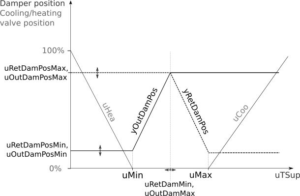
This is a multi zone VAV AHU economizer modulation block. It calculates
the outdoor and return air damper positions based on the supply air temperature
control loop signal. The implementation is in line with ASHRAE
Guidline 36 (G36), PART 5.N.2.c. Damper positions are linearly mapped to
the supply air control loop signal. This is a final sequence in the
composite multi zone VAV AHU economizer control sequence. Damper position
limits, which are the inputs to the sequence, are the outputs of
Buildings.Controls.OBC.ASHRAE.G36_PR1.AHUs.MultiZone.VAV.Economizers.Subsequences.Limits and
Buildings.Controls.OBC.ASHRAE.G36_PR1.AHUs.MultiZone.VAV.Economizers.Subsequences.Enable
sequences.
When the economizer is enabled, the PI controller modulates the damper
positions. Return and outdoor damper are not interlocked. When the economizer is disabled,
the damper positions are set to the minimum outdoor air damper position limits.
The control charts below show the input-output structure and an economizer damper
modulation sequence assuming a well configured controller. Control diagram:

Multi zone AHU economizer modulation control chart:
Parameters
| Type | Name | Default | Description |
|---|
| Commissioning |
| Controller |
| Real | uMin | -0.25 | Lower limit of controller input when outdoor damper opens (see diagram) [1] |
| Real | uMax | +0.25 | Upper limit of controller input when return damper is closed (see diagram) [1] |
| Real | uOutDamMax | (uMin + uMax)/2 | Maximum loop signal for the OA damper to be fully open [1] |
| Real | uRetDamMin | (uMin + uMax)/2 | Minimum loop signal for the RA damper to be fully open [1] |
Connectors
| Type | Name | Description |
|---|
| input RealInput | uTSup | Signal for supply air temperature control (T Sup Control Loop Signal in diagram) [1] |
| input RealInput | uOutDamPosMin | Minimum economizer damper position limit as returned by the damper position limits sequence [1] |
| input RealInput | uOutDamPosMax | Maximum economizer damper position limit as returned by the economizer enable-disable sequence.
If the economizer is disabled, this value equals uOutDamPosMin [1] |
| input RealInput | uRetDamPosMin | Minimum return air damper position limit as returned by the economizer enable-disable sequence [1] |
| input RealInput | uRetDamPosMax | Maximum return air damper position limit as returned by the economizer enable-disable sequence [1] |
| output RealOutput | yOutDamPos | Economizer damper position [1] |
| output RealOutput | yRetDamPos | Return air damper position [1] |
Modelica definition
block Modulation
parameter Real uMin(
final max=0,
final unit="1")=-0.25
;
parameter Real uMax(
final min=0,
final unit="1")=+0.25
;
parameter Real uOutDamMax(
final min=-1,
final max=1,
final unit="1") = (uMin + uMax)/2
;
parameter Real uRetDamMin(
final min=-1,
final max=1,
final unit="1") = (uMin + uMax)/2
;
Buildings.Controls.OBC.CDL.Interfaces.RealInput uTSup(
final unit="1")
;
Buildings.Controls.OBC.CDL.Interfaces.RealInput uOutDamPosMin(
final min=0,
final max=1,
final unit="1")
;
Buildings.Controls.OBC.CDL.Interfaces.RealInput uOutDamPosMax(
final min=0,
final max=1,
final unit="1") ;
Buildings.Controls.OBC.CDL.Interfaces.RealInput uRetDamPosMin(
final min=0,
final max=1,
final unit="1")
;
Buildings.Controls.OBC.CDL.Interfaces.RealInput uRetDamPosMax(
final min=0,
final max=1,
final unit="1")
;
Buildings.Controls.OBC.CDL.Interfaces.RealOutput yOutDamPos(
final min=0,
final max=1,
final unit="1") ;
Buildings.Controls.OBC.CDL.Interfaces.RealOutput yRetDamPos(
final min=0,
final max=1,
final unit="1") ;
protected
Buildings.Controls.OBC.CDL.Continuous.Sources.Constant outDamMinLimSig(
final k=uMin) ;
Buildings.Controls.OBC.CDL.Continuous.Sources.Constant outDamMaxLimSig(
final k=uOutDamMax) ;
Buildings.Controls.OBC.CDL.Continuous.Sources.Constant retDamConMinLimSig(
final k=uRetDamMin)
;
Buildings.Controls.OBC.CDL.Continuous.Sources.Constant retDamMaxLimSig(
final k=uMax) ;
Buildings.Controls.OBC.CDL.Continuous.Line outDamPos(
final limitBelow=true,
final limitAbove=true)
;
Buildings.Controls.OBC.CDL.Continuous.Line retDamPos(
final limitBelow=true,
final limitAbove=true)
;
Buildings.Controls.OBC.CDL.Continuous.Min min ;
Buildings.Controls.OBC.CDL.Continuous.Max max ;
equation
connect(outDamPos.x2, outDamMaxLimSig.y);
connect(outDamPos.x1, outDamMinLimSig.y);
connect(outDamPos.f1, uOutDamPosMin);
connect(outDamPos.f2, uOutDamPosMax);
connect(retDamPos.x2, retDamMaxLimSig.y);
connect(retDamPos.x1, retDamConMinLimSig.y);
connect(retDamPos.f1, uRetDamPosMax);
connect(retDamPos.f2, uRetDamPosMin);
connect(min.u2, uOutDamPosMax);
connect(min.u1, outDamPos.y);
connect(max.u1, retDamPos.y);
connect(uRetDamPosMin, max.u2);
connect(uTSup, retDamPos.u);
connect(uTSup, outDamPos.u);
connect(yOutDamPos, min.y);
connect(max.y, yRetDamPos);
end Modulation;
 Buildings.Controls.OBC.ASHRAE.G36_PR1.AHUs.MultiZone.VAV.Economizers.Subsequences.Enable
 Buildings.Controls.OBC.ASHRAE.G36_PR1.AHUs.MultiZone.VAV.Economizers.Subsequences.Limits
 Buildings.Controls.OBC.ASHRAE.G36_PR1.AHUs.MultiZone.VAV.Economizers.Subsequences.Modulation