Buildings.Fluid.HeatPumps
Package with models for heat pumps
Information
This package contains component models for heat pumps.
Extends from Modelica.Icons.VariantsPackage (Icon for package containing variants).
Package Content
| Name | Description |
|---|---|
| Heat pump with prescribed condenser leaving temperature and performance curve adjusted based on Carnot efficiency | |
| Reversible heat pump with performance curve adjusted based on Carnot efficiency | |
| Model for a reversable heat pump based on the equation fit method | |
| Model for a reciprocating water to water heat pump | |
| Model for a scroll water to water heat pump | |
| Package for calibration of heat pump models | |
| Package with compressor models | |
| Package with model parameters for heat pumps | |
| Collection of models that illustrate model use and test models | |
| Collection of models that validate the heat pump models | |
| Package with base classes for Buildings.Fluid.HeatPumps |
 Buildings.Fluid.HeatPumps.Carnot_TCon
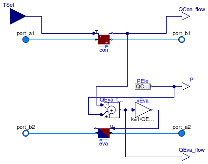
Heat pump with prescribed condenser leaving temperature and performance curve adjusted based on Carnot efficiency
Information
This is a model of a heat pump whose coefficient of performance COP changes with temperatures in the same way as the Carnot efficiency changes. The control input is the setpoint of the condenser leaving temperature, which is met exactly at steady state if the heat pump has sufficient capacity.
The model allows to either specify the Carnot effectivness ηCarnot,0, or a COP0 at the nominal conditions, together with the evaporator temperature Teva,0 and the condenser temperature Tcon,0, in which case the model computes the Carnot effectivness as
ηCarnot,0 = COP0 ⁄ (Tcon,0 ⁄ (Tcon,0-Teva,0)).
The heat pump COP is computed as the product
COP = ηCarnot,0 COPCarnot ηPL,
where COPCarnot is the Carnot efficiency and ηPL is a polynomial in heating part load ratio yPL that can be used to take into account a change in COP at part load conditions. This polynomial has the form
ηPL = a1 + a2 yPL + a3 yPL2 + ...
where the coefficients ai
are declared by the parameter a.
On the Dynamics tag, the model can be parametrized to compute a transient
or steady-state response.
The transient response of the model is computed using a first
order differential equation for the evaporator and condenser fluid volumes.
The heat pump outlet temperatures are equal to the temperatures of these lumped volumes.
Typical use and important parameters
When using this component, make sure that the condenser has sufficient mass flow rate. Based on the evaporator mass flow rate, temperature difference and the efficiencies, the model computes how much heat will be removed by to the evaporator. If the mass flow rate is too small, very low outlet temperatures can result, possibly below freezing.
The condenser heat flow rate QCon_flow_nominal is used to assign
the default value for the mass flow rates, which are used for the pressure drop
calculations.
It is also used to compute the part load efficiency.
Hence, make sure that QCon_flow_nominal is set to a reasonable value.
The maximum heating capacity is set by the parameter QCon_flow_max,
which is by default set to infinity.
The coefficient of performance depends on the evaporator and condenser leaving temperature since otherwise the second law of thermodynamics may be violated.
Notes
For a similar model that can be used as a chiller, see Buildings.Fluid.Chillers.Examples.Carnot_TEva.
Extends from Buildings.Fluid.Chillers.BaseClasses.PartialCarnot_T (Partial model for chiller with performance curve adjusted based on Carnot efficiency).
Parameters
| Type | Name | Default | Description |
|---|---|---|---|
| replaceable package Medium1 | PartialMedium | Medium 1 in the component | |
| replaceable package Medium2 | PartialMedium | Medium 2 in the component | |
| HeatFlowRate | QCon_flow_max | Modelica.Constants.inf | Maximum heat flow rate for heating (positive) [W] |
| Nominal condition | |||
| MassFlowRate | m1_flow_nominal | QCon_flow_nominal/cp1_defaul... | Nominal mass flow rate [kg/s] |
| MassFlowRate | m2_flow_nominal | QEva_flow_nominal/cp2_defaul... | Nominal mass flow rate [kg/s] |
| HeatFlowRate | QEva_flow_nominal | -QCon_flow_nominal*(COP_nomi... | Nominal cooling heat flow rate (QEva_flow_nominal < 0) [W] |
| HeatFlowRate | QCon_flow_nominal | Nominal heating flow rate [W] | |
| TemperatureDifference | dTEva_nominal | -10 | Temperature difference evaporator outlet-inlet [K] |
| TemperatureDifference | dTCon_nominal | 10 | Temperature difference condenser outlet-inlet [K] |
| Pressure | dp1_nominal | Pressure difference over condenser [Pa] | |
| Pressure | dp2_nominal | Pressure difference over evaporator [Pa] | |
| Efficiency | |||
| Boolean | use_eta_Carnot_nominal | true | Set to true to use Carnot effectiveness etaCarnot_nominal rather than COP_nominal |
| Real | etaCarnot_nominal | COP_nominal/(TUseAct_nominal... | Carnot effectiveness (=COP/COP_Carnot) used if use_eta_Carnot_nominal = true [1] |
| Real | COP_nominal | etaCarnot_nominal*TUseAct_no... | Coefficient of performance at TEva_nominal and TCon_nominal, used if use_eta_Carnot_nominal = false [1] |
| Temperature | TCon_nominal | 303.15 | Condenser temperature used to compute COP_nominal if use_eta_Carnot_nominal=false [K] |
| Temperature | TEva_nominal | 278.15 | Evaporator temperature used to compute COP_nominal if use_eta_Carnot_nominal=false [K] |
| Real | a[:] | {1} | Coefficients for efficiency curve (need p(a=a, yPL=1)=1) |
| TemperatureDifference | TAppCon_nominal | if cp1_default < 1500 then 5... | Temperature difference between refrigerant and working fluid outlet in condenser [K] |
| TemperatureDifference | TAppEva_nominal | if cp2_default < 1500 then 5... | Temperature difference between refrigerant and working fluid outlet in evaporator [K] |
| Assumptions | |||
| Boolean | allowFlowReversal1 | true | = false to simplify equations, assuming, but not enforcing, no flow reversal for medium 1 |
| Boolean | allowFlowReversal2 | true | = false to simplify equations, assuming, but not enforcing, no flow reversal for medium 2 |
| Advanced | |||
| MassFlowRate | m1_flow_small | 1E-4*abs(m1_flow_nominal) | Small mass flow rate for regularization of zero flow [kg/s] |
| MassFlowRate | m2_flow_small | 1E-4*abs(m2_flow_nominal) | Small mass flow rate for regularization of zero flow [kg/s] |
| Diagnostics | |||
| Boolean | show_T | false | = true, if actual temperature at port is computed |
| Flow resistance | |||
| Condenser | |||
| Boolean | from_dp1 | false | = true, use m_flow = f(dp) else dp = f(m_flow) |
| Boolean | linearizeFlowResistance1 | false | = true, use linear relation between m_flow and dp for any flow rate |
| Real | deltaM1 | 0.1 | Fraction of nominal flow rate where flow transitions to laminar [1] |
| Evaporator | |||
| Boolean | from_dp2 | false | = true, use m_flow = f(dp) else dp = f(m_flow) |
| Boolean | linearizeFlowResistance2 | false | = true, use linear relation between m_flow and dp for any flow rate |
| Real | deltaM2 | 0.1 | Fraction of nominal flow rate where flow transitions to laminar [1] |
| Dynamics | |||
| Condenser | |||
| Time | tau1 | 60 | Time constant at nominal flow rate (used if energyDynamics1 <> Modelica.Fluid.Types.Dynamics.SteadyState) [s] |
| Temperature | T1_start | Medium1.T_default | Initial or guess value of set point [K] |
| Evaporator | |||
| Time | tau2 | 60 | Time constant at nominal flow rate (used if energyDynamics2 <> Modelica.Fluid.Types.Dynamics.SteadyState) [s] |
| Temperature | T2_start | Medium2.T_default | Initial or guess value of set point [K] |
| Evaporator and condenser | |||
| Dynamics | energyDynamics | Modelica.Fluid.Types.Dynamic... | Type of energy balance: dynamic (3 initialization options) or steady state |
Connectors
| Type | Name | Description |
|---|---|---|
| FluidPort_a | port_a1 | Fluid connector a1 (positive design flow direction is from port_a1 to port_b1) |
| FluidPort_b | port_b1 | Fluid connector b1 (positive design flow direction is from port_a1 to port_b1) |
| FluidPort_a | port_a2 | Fluid connector a2 (positive design flow direction is from port_a2 to port_b2) |
| FluidPort_b | port_b2 | Fluid connector b2 (positive design flow direction is from port_a2 to port_b2) |
| output RealOutput | QCon_flow | Actual heating heat flow rate added to fluid 1 [W] |
| output RealOutput | P | Electric power consumed by compressor [W] |
| output RealOutput | QEva_flow | Actual cooling heat flow rate removed from fluid 2 [W] |
| input RealInput | TSet | Condenser leaving water temperature [K] |
Modelica definition
 Buildings.Fluid.HeatPumps.Carnot_y
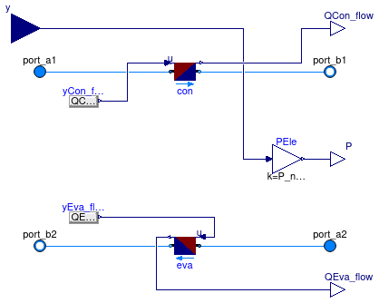
Reversible heat pump with performance curve adjusted based on Carnot efficiency
Information
This is model of a heat pump whose coefficient of performance COP changes with temperatures in the same way as the Carnot efficiency changes. The input signal y is the control signal for the compressor.
The model allows to either specify the Carnot effectivness ηCarnot,0, or a COP0 at the nominal conditions, together with the evaporator temperature Teva,0 and the condenser temperature Tcon,0, in which case the model computes the Carnot effectivness as
ηCarnot,0 = COP0 ⁄ (Tcon,0 ⁄ (Tcon,0-Teva,0)).
The heat pump COP is computed as the product
COP = ηCarnot,0 COPCarnot ηPL,
where COPCarnot is the Carnot efficiency and ηPL is a polynomial in the heating part load ratio yPL that can be used to take into account a change in COP at part load conditions. This polynomial has the form
ηPL = a1 + a2 yPL + a3 yPL2 + ...
where the coefficients ai are declared by the parameter a.
On the Dynamics tag, the model can be parametrized to compute a transient
or steady-state response.
The transient response of the model is computed using a first
order differential equation for the evaporator and condenser fluid volumes.
The heat pump outlet temperatures are equal to the temperatures of these lumped volumes.
Typical use and important parameters
When using this component, make sure that the evaporator and the condenser have sufficient mass flow rate. Based on the mass flow rates, the compressor power, temperature difference and the efficiencies, the model computes how much heat will be added to the condenser and removed at the evaporator. If the mass flow rates are too small, very high temperature differences can result.
The condenser heat flow rate QCon_flow_nominal is used to assign
the default value for the mass flow rates, which are used for the pressure drop
calculations.
It is also used to compute the part load efficiency.
Hence, make sure that QCon_flow_nominal is set to a reasonable value.
The maximum heating capacity is set by the parameter QCon_flow_max,
which is by default set to infinity.
The coefficient of performance depends on the evaporator and condenser leaving temperature since otherwise the second law of thermodynamics may be violated.
Notes
For a similar model that can be used as a chiller, see Buildings.Fluid.Chillers.Carnot_y.
Extends from Buildings.Fluid.Chillers.BaseClasses.PartialCarnot_y (Partial chiller model with performance curve adjusted based on Carnot efficiency).
Parameters
| Type | Name | Default | Description |
|---|---|---|---|
| replaceable package Medium1 | PartialMedium | Medium 1 in the component | |
| replaceable package Medium2 | PartialMedium | Medium 2 in the component | |
| Nominal condition | |||
| MassFlowRate | m1_flow_nominal | QCon_flow_nominal/cp1_defaul... | Nominal mass flow rate [kg/s] |
| MassFlowRate | m2_flow_nominal | QEva_flow_nominal/cp2_defaul... | Nominal mass flow rate [kg/s] |
| TemperatureDifference | dTEva_nominal | -10 | Temperature difference evaporator outlet-inlet [K] |
| TemperatureDifference | dTCon_nominal | 10 | Temperature difference condenser outlet-inlet [K] |
| Pressure | dp1_nominal | Pressure difference over condenser [Pa] | |
| Pressure | dp2_nominal | Pressure difference over evaporator [Pa] | |
| Power | P_nominal | Nominal compressor power (at y=1) [W] | |
| Efficiency | |||
| Boolean | use_eta_Carnot_nominal | true | Set to true to use Carnot effectiveness etaCarnot_nominal rather than COP_nominal |
| Real | etaCarnot_nominal | COP_nominal/(TUseAct_nominal... | Carnot effectiveness (=COP/COP_Carnot) used if use_eta_Carnot_nominal = true [1] |
| Real | COP_nominal | etaCarnot_nominal*TUseAct_no... | Coefficient of performance at TEva_nominal and TCon_nominal, used if use_eta_Carnot_nominal = false [1] |
| Temperature | TCon_nominal | 303.15 | Condenser temperature used to compute COP_nominal if use_eta_Carnot_nominal=false [K] |
| Temperature | TEva_nominal | 278.15 | Evaporator temperature used to compute COP_nominal if use_eta_Carnot_nominal=false [K] |
| Real | a[:] | {1} | Coefficients for efficiency curve (need p(a=a, yPL=1)=1) |
| TemperatureDifference | TAppCon_nominal | if cp1_default < 1500 then 5... | Temperature difference between refrigerant and working fluid outlet in condenser [K] |
| TemperatureDifference | TAppEva_nominal | if cp2_default < 1500 then 5... | Temperature difference between refrigerant and working fluid outlet in evaporator [K] |
| Assumptions | |||
| Boolean | allowFlowReversal1 | true | = false to simplify equations, assuming, but not enforcing, no flow reversal for medium 1 |
| Boolean | allowFlowReversal2 | true | = false to simplify equations, assuming, but not enforcing, no flow reversal for medium 2 |
| Advanced | |||
| MassFlowRate | m1_flow_small | 1E-4*abs(m1_flow_nominal) | Small mass flow rate for regularization of zero flow [kg/s] |
| MassFlowRate | m2_flow_small | 1E-4*abs(m2_flow_nominal) | Small mass flow rate for regularization of zero flow [kg/s] |
| Diagnostics | |||
| Boolean | show_T | false | = true, if actual temperature at port is computed |
| Flow resistance | |||
| Condenser | |||
| Boolean | from_dp1 | false | = true, use m_flow = f(dp) else dp = f(m_flow) |
| Boolean | linearizeFlowResistance1 | false | = true, use linear relation between m_flow and dp for any flow rate |
| Real | deltaM1 | 0.1 | Fraction of nominal flow rate where flow transitions to laminar [1] |
| Evaporator | |||
| Boolean | from_dp2 | false | = true, use m_flow = f(dp) else dp = f(m_flow) |
| Boolean | linearizeFlowResistance2 | false | = true, use linear relation between m_flow and dp for any flow rate |
| Real | deltaM2 | 0.1 | Fraction of nominal flow rate where flow transitions to laminar [1] |
| Dynamics | |||
| Condenser | |||
| Time | tau1 | 60 | Time constant at nominal flow rate (used if energyDynamics1 <> Modelica.Fluid.Types.Dynamics.SteadyState) [s] |
| Temperature | T1_start | Medium1.T_default | Initial or guess value of set point [K] |
| Evaporator | |||
| Time | tau2 | 60 | Time constant at nominal flow rate (used if energyDynamics2 <> Modelica.Fluid.Types.Dynamics.SteadyState) [s] |
| Temperature | T2_start | Medium2.T_default | Initial or guess value of set point [K] |
| Evaporator and condenser | |||
| Dynamics | energyDynamics | Modelica.Fluid.Types.Dynamic... | Type of energy balance: dynamic (3 initialization options) or steady state |
Connectors
| Type | Name | Description |
|---|---|---|
| FluidPort_a | port_a1 | Fluid connector a1 (positive design flow direction is from port_a1 to port_b1) |
| FluidPort_b | port_b1 | Fluid connector b1 (positive design flow direction is from port_a1 to port_b1) |
| FluidPort_a | port_a2 | Fluid connector a2 (positive design flow direction is from port_a2 to port_b2) |
| FluidPort_b | port_b2 | Fluid connector b2 (positive design flow direction is from port_a2 to port_b2) |
| output RealOutput | QCon_flow | Actual heating heat flow rate added to fluid 1 [W] |
| output RealOutput | P | Electric power consumed by compressor [W] |
| output RealOutput | QEva_flow | Actual cooling heat flow rate removed from fluid 2 [W] |
| input RealInput | y | Part load ratio of compressor [1] |
Modelica definition
 Buildings.Fluid.HeatPumps.EquationFitReversible
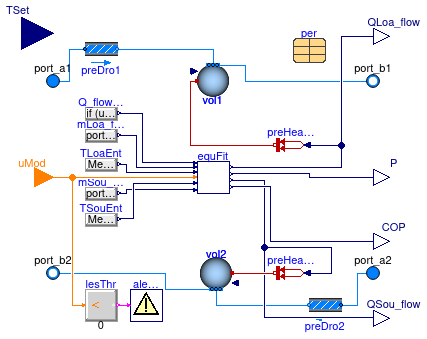
Model for a reversable heat pump based on the equation fit method
Information
Model for a reversable heat pump using the equation fit method and that takes as an input the set point for the leaving fluid temperature.
This reversable heat pump can be operated either in heating mode or in cooling mode.
It typically is used for a water to water heat pump, but if the performance data
per are set up for other media, such as glycol, it can also be used for
such applications.
Note that if used with air, the results will only be valid if there is no
humidity condensation or frost build up.
The heat exchanger at medium 1 is to be connected to the building load,
and the other heat exchanger to the heat source or sink, such as
a geothermal loop.
If in heating mode, the heat exchanger at medium 1 operates as a condenser,
and in cooling mode it operates as an evaporator.
The model is based on the model described in the EnergyPlus 9.1.0 Engineering Reference, Section 16.6.1: Water to water heat pump model and the model based on C.Tang (2005).
The model takes the following control signals:
-
The integer input
uModwhich controls the heat pump operational mode. Ifper.reverseCycle = truethe signal can take on the values -1 for cooling mode, 0 for off and +1 for heating mode.
Ifper.reverseCycle = falseanduMod = -1, the model stops with an error message. -
The input
TSetis the set point for the leaving fluid temperature at portport_b1.
The heating and cooling performance coefficients are stored in the data record per and are available from
Buildings.Fluid.HeatPumps.Data.EquationFitReversible.
The electric power only includes the power for the compressor, but not any power for pumps, as the pumps must be modeled outside of this component.
Main equations
The performance of the heat pump is computed as follows:
Let α be the set of heat load performance coefficients determined by the data
record per.hea.coeQ and let
β be the set of electrical power performance coefficients determined by the data
record hea.coeP.
Then, the performance is computed as
-
If
uMod = 1, the heat pump is in heating mode and the load side available heat isQ̇ava = ( α1 + α2 Tloa,ent/TRefHeaLoa + α3 Tsou,ent/TRefHeaSou + α4 ṁloa,ent/(ṁloa,0 s) + α5 ṁsou,ent/(ṁsou,0 s) ) Q̇0 s,
where Q̇0 is the design capacity as specified by the parameter
per.hea.Q_flowand s is the scaling factor specified by the parameterscaling_factor. The corresponding power consumption isP= ( β1 + β2 Tloa,ent/TRefHeaLoa + β3 Tsou,ent/TRefHeaSou + β4 ṁloa,ent/(ṁloa,0 s) + β5 ṁsou,ent/(ṁsou,0 s) ) P0 s,
where P0 is the design power consumption as specified by the parameter
per.hea.P. The actual heat provided at the load side isQ̇ = min(Q̇ava , Q̇set),
where Q̇set is the heat required to meet the temperature setpoint for the leaving fluid on the load side.
-
If
uMod = -1, the heat pump is in cooling mode, and the governing equations are as above, but withper.coorather thanper.heaused for the performance data, and the min(· ·) function replaced with max(· ·). -
If
uMod = 0, the model sets Q̇ = 0 and P = 0.
The coefficient of performance COP is computed as
COP = Q̇ ⁄ P.
References
C. Tang Equation fit based models of water source heat pumps. Master Thesis. Oklahoma State University, Oklahoma, USA. 2005.
Extends from Buildings.Fluid.Interfaces.FourPortHeatMassExchanger (Model transporting two fluid streams between four ports with storing mass or energy).
Parameters
| Type | Name | Default | Description |
|---|---|---|---|
| replaceable package Medium1 | PartialMedium | Medium 1 in the component | |
| replaceable package Medium2 | PartialMedium | Medium 2 in the component | |
| Generic | per | Performance data | |
| Real | scaling_factor | 1 | Scaling factor for heat pump capacity |
| Nominal condition | |||
| MassFlowRate | m1_flow_nominal | per.hea.mLoa_flow*scaling_fa... | Nominal mass flow rate [kg/s] |
| MassFlowRate | m2_flow_nominal | per.hea.mSou_flow*scaling_fa... | Nominal mass flow rate [kg/s] |
| PressureDifference | dp1_nominal | per.dpHeaLoa_nominal | Pressure difference [Pa] |
| PressureDifference | dp2_nominal | per.dpHeaSou_nominal | Pressure difference [Pa] |
| Assumptions | |||
| Boolean | allowFlowReversal1 | true | = false to simplify equations, assuming, but not enforcing, no flow reversal for medium 1 |
| Boolean | allowFlowReversal2 | true | = false to simplify equations, assuming, but not enforcing, no flow reversal for medium 2 |
| Advanced | |||
| MassFlowRate | m1_flow_small | 1E-4*abs(m1_flow_nominal) | Small mass flow rate for regularization of zero flow [kg/s] |
| MassFlowRate | m2_flow_small | 1E-4*abs(m2_flow_nominal) | Small mass flow rate for regularization of zero flow [kg/s] |
| HeatFlowRate | Q_flow_small | per.hea.Q_flow*scaling_facto... | Small value for heat flow rate or power, used to avoid division by zero [W] |
| Diagnostics | |||
| Boolean | show_T | true | = true, if actual temperature at port is computed |
| Flow resistance | |||
| Medium 1 | |||
| Boolean | from_dp1 | false | = true, use m_flow = f(dp) else dp = f(m_flow) |
| Boolean | linearizeFlowResistance1 | false | = true, use linear relation between m_flow and dp for any flow rate |
| Real | deltaM1 | 0.1 | Fraction of nominal flow rate where flow transitions to laminar |
| Medium 2 | |||
| Boolean | from_dp2 | false | = true, use m_flow = f(dp) else dp = f(m_flow) |
| Boolean | linearizeFlowResistance2 | false | = true, use linear relation between m_flow and dp for any flow rate |
| Real | deltaM2 | 0.1 | Fraction of nominal flow rate where flow transitions to laminar |
| Dynamics | |||
| Nominal condition | |||
| Time | tau1 | 30 | Time constant at nominal flow [s] |
| Time | tau2 | 30 | Time constant at nominal flow [s] |
| Conservation equations | |||
| Dynamics | energyDynamics | Modelica.Fluid.Types.Dynamic... | Type of energy balance: dynamic (3 initialization options) or steady state |
| Initialization | |||
| Medium 1 | |||
| AbsolutePressure | p1_start | Medium1.p_default | Start value of pressure [Pa] |
| Temperature | T1_start | Medium1.T_default | Start value of temperature [K] |
| MassFraction | X1_start[Medium1.nX] | Medium1.X_default | Start value of mass fractions m_i/m [kg/kg] |
| ExtraProperty | C1_start[Medium1.nC] | fill(0, Medium1.nC) | Start value of trace substances |
| ExtraProperty | C1_nominal[Medium1.nC] | fill(1E-2, Medium1.nC) | Nominal value of trace substances. (Set to typical order of magnitude.) |
| Medium 2 | |||
| AbsolutePressure | p2_start | Medium2.p_default | Start value of pressure [Pa] |
| Temperature | T2_start | Medium2.T_default | Start value of temperature [K] |
| MassFraction | X2_start[Medium2.nX] | Medium2.X_default | Start value of mass fractions m_i/m [kg/kg] |
| ExtraProperty | C2_start[Medium2.nC] | fill(0, Medium2.nC) | Start value of trace substances |
| ExtraProperty | C2_nominal[Medium2.nC] | fill(1E-2, Medium2.nC) | Nominal value of trace substances. (Set to typical order of magnitude.) |
Connectors
| Type | Name | Description |
|---|---|---|
| FluidPort_a | port_a1 | Fluid connector a1 (positive design flow direction is from port_a1 to port_b1) |
| FluidPort_b | port_b1 | Fluid connector b1 (positive design flow direction is from port_a1 to port_b1) |
| FluidPort_a | port_a2 | Fluid connector a2 (positive design flow direction is from port_a2 to port_b2) |
| FluidPort_b | port_b2 | Fluid connector b2 (positive design flow direction is from port_a2 to port_b2) |
| input IntegerInput | uMod | Control input signal, cooling mode=-1, off=0, heating mode=+1 |
| input RealInput | TSet | Set point for leaving fluid temperature at port b1 [K] |
| output RealOutput | P | Compressor power [W] |
| output RealOutput | QSou_flow | Heat flow rate at the source heat exchanger [W] |
| output RealOutput | QLoa_flow | Heat flow rate at the load heat exchanger [W] |
| output RealOutput | COP | Coefficient of performance, assuming useful heat is at load side (at Medium 1) [1] |
Modelica definition
 Buildings.Fluid.HeatPumps.ReciprocatingWaterToWater
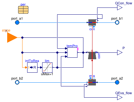
Model for a reciprocating water to water heat pump
Information
Model for a water to water heat pump with a reciprocating compressor, as described in Jin (2002). The thermodynamic heat pump cycle is represented below.
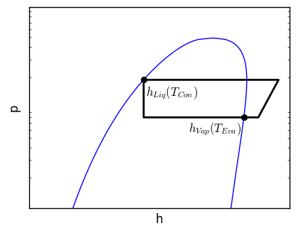
The rate of heat transferred to the evaporator is given by:
Q̇Eva = ṁref ( hVap(TEva) - hLiq(TCon) ).
The power consumed by the compressor is given by a linear efficiency relation:
P = PTheoretical / η + PLoss,constant.
Heat transfer in the evaporator and condenser is calculated using an ε-NTU method, assuming constant refrigerant temperature and constant heat transfer coefficient between fluid and refrigerant.
Variable speed is acheived by multiplying the full load piston displacement by the normalized compressor speed. The power and heat transfer rates are forced to zero if the resulting heat pump state has higher evaporating pressure than condensing pressure.
Options
Parameters TConMax and TEvaMin
may be used to set an upper or lower bound for the
condenser and evaporator.
The compressor is disabled when these conditions
are not satisfied, or when the
evaporator temperature is larger
than the condenser temperature.
This mimics the temperature protection
of heat pumps and moreover it avoids
non-converging algebraic loops of equations,
or freezing of evaporator medium.
This option can be disabled by setting
enable_temperature_protection = false.
Assumptions and limitations
The compression process is assumed isentropic. The thermal energy of superheating is ignored in the evaluation of the heat transferred to the refrigerant in the evaporator. There is no supercooling.
References
H. Jin. Parameter estimation based models of water source heat pumps. PhD Thesis. Oklahoma State University. Stillwater, Oklahoma, USA. 2002.
Extends from Buildings.Fluid.HeatPumps.BaseClasses.PartialWaterToWater (Partial model for water to water heat pumps and chillers).
Parameters
| Type | Name | Default | Description |
|---|---|---|---|
| replaceable package Medium1 | PartialMedium | Medium 1 in the component | |
| replaceable package Medium2 | PartialMedium | Medium 2 in the component | |
| replaceable package ref | R410A | Refrigerant in the component | |
| Boolean | enable_variable_speed | true | Set to true to allow modulating of compressor speed |
| Real | scaling_factor | 1.0 | Scaling factor for heat pump capacity |
| ThermalConductance | UACon | per.UACon*scaling_factor | Thermal conductance of condenser [W/K] |
| ThermalConductance | UAEva | per.UAEva*scaling_factor | Thermal conductance of evaporator [W/K] |
| Generic | per | Heat pump performance data | |
| Nominal condition | |||
| MassFlowRate | m1_flow_nominal | Nominal mass flow rate [kg/s] | |
| MassFlowRate | m2_flow_nominal | Nominal mass flow rate [kg/s] | |
| PressureDifference | dp1_nominal | Pressure difference [Pa] | |
| PressureDifference | dp2_nominal | Pressure difference [Pa] | |
| Temperature protection | |||
| Boolean | enable_temperature_protection | true | Enable temperature protection |
| Temperature | TConMax | ref.TCri - 5 | Upper bound for condenser temperature [K] |
| Temperature | TEvaMin | 275.15 | Lower bound for evaporator temperature [K] |
| Real | dTHys | 5 | Hysteresis interval width [K] |
| Assumptions | |||
| Boolean | allowFlowReversal1 | true | = false to simplify equations, assuming, but not enforcing, no flow reversal for medium 1 |
| Boolean | allowFlowReversal2 | true | = false to simplify equations, assuming, but not enforcing, no flow reversal for medium 2 |
| Advanced | |||
| MassFlowRate | m1_flow_small | 1E-4*abs(m1_flow_nominal) | Small mass flow rate for regularization of zero flow [kg/s] |
| MassFlowRate | m2_flow_small | 1E-4*abs(m2_flow_nominal) | Small mass flow rate for regularization of zero flow [kg/s] |
| Diagnostics | |||
| Boolean | show_T | false | = true, if actual temperature at port is computed |
| Flow resistance | |||
| Medium 1 | |||
| Boolean | from_dp1 | false | = true, use m_flow = f(dp) else dp = f(m_flow) |
| Boolean | linearizeFlowResistance1 | false | = true, use linear relation between m_flow and dp for any flow rate |
| Real | deltaM1 | 0.1 | Fraction of nominal flow rate where flow transitions to laminar |
| Medium 2 | |||
| Boolean | from_dp2 | false | = true, use m_flow = f(dp) else dp = f(m_flow) |
| Boolean | linearizeFlowResistance2 | false | = true, use linear relation between m_flow and dp for any flow rate |
| Real | deltaM2 | 0.1 | Fraction of nominal flow rate where flow transitions to laminar |
| Dynamics | |||
| Condenser | |||
| Time | tau1 | 60 | Time constant at nominal flow rate (used if energyDynamics1 <> Modelica.Fluid.Types.Dynamics.SteadyState) [s] |
| Temperature | T1_start | Medium1.T_default | Initial or guess value of set point [K] |
| Evaporator | |||
| Time | tau2 | 60 | Time constant at nominal flow rate (used if energyDynamics2 <> Modelica.Fluid.Types.Dynamics.SteadyState) [s] |
| Temperature | T2_start | Medium2.T_default | Initial or guess value of set point [K] |
| Evaporator and condenser | |||
| Dynamics | energyDynamics | Modelica.Fluid.Types.Dynamic... | Type of energy balance: dynamic (3 initialization options) or steady state |
Connectors
| Type | Name | Description |
|---|---|---|
| FluidPort_a | port_a1 | Fluid connector a1 (positive design flow direction is from port_a1 to port_b1) |
| FluidPort_b | port_b1 | Fluid connector b1 (positive design flow direction is from port_a1 to port_b1) |
| FluidPort_a | port_a2 | Fluid connector a2 (positive design flow direction is from port_a2 to port_b2) |
| FluidPort_b | port_b2 | Fluid connector b2 (positive design flow direction is from port_a2 to port_b2) |
| output BooleanOutput | errLowPre | if true, compressor disabled since evaporator temperature is above upper bound |
| output BooleanOutput | errHigPre | if true, compressor disabled since condenser temperature is below lower bound |
| output BooleanOutput | errNegTemDif | if true, compressor disabled since condenser temperature is below evaporator temperature |
| input RealInput | y | Modulating signal for compressor frequency, equal to 1 at full load condition [1] |
| input IntegerInput | stage | Current stage of the heat pump, equal to 1 at full load condition |
| output RealOutput | QCon_flow | Actual heating heat flow rate added to fluid 1 [W] |
| output RealOutput | P | Electric power consumed by compressor [W] |
| output RealOutput | QEva_flow | Actual cooling heat flow rate removed from fluid 2 [W] |
Modelica definition
Buildings.Fluid.HeatPumps.ScrollWaterToWater
Model for a scroll water to water heat pump
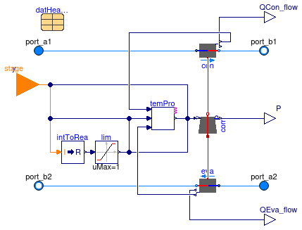
Information
Model for a water to water heat pump with a scroll compressor, as described in Jin (2002). The thermodynamic heat pump cycle is represented below.
The rate of heat transferred to the evaporator is given by:
Q̇Eva = ṁref ( hVap(TEva) - hLiq(TCon) ).
The power consumed by the compressor is given by a linear efficiency relation:
P = PTheoretical / η + PLoss,constant.
Heat transfer in the evaporator and condenser is calculated using an ε-NTU method, assuming constant refrigerant temperature and constant heat transfer coefficient between fluid and refrigerant.
Variable speed is achieved by multiplying the full load suction volume flow rate by the normalized compressor speed. The power and heat transfer rates are forced to zero if the resulting heat pump state has higher evaporating pressure than condensing pressure.
The model parameters are obtained by calibration of the heat pump model to manufacturer performance data. Calibrated model parameters for various heat pumps from different manufacturers are found in Buildings.Fluid.HeatPumps.Data.ScrollWaterToWater. The calibrated model is located in Buildings.Fluid.HeatPumps.Calibration.ScrollWaterToWater.
Options
Parameters TConMax and TEvaMin
may be used to set an upper or lower bound for the
condenser and evaporator.
The compressor is disabled when these conditions
are not satisfied, or when the
evaporator temperature is larger
than the condenser temperature.
This mimics the temperature protection
of heat pumps and moreover it avoids
non-converging algebraic loops of equations,
or freezing of evaporator medium.
This option can be disabled by setting
enable_temperature_protection = false.
Assumptions and limitations
The compression process is assumed isentropic. The thermal energy of superheating is ignored in the evaluation of the heat transferred to the refrigerant in the evaporator. There is no supercooling.
References
H. Jin. Parameter estimation based models of water source heat pumps. PhD Thesis. Oklahoma State University. Stillwater, Oklahoma, USA. 2002.
Extends from Buildings.Fluid.HeatPumps.BaseClasses.PartialWaterToWater (Partial model for water to water heat pumps and chillers).
Parameters
| Type | Name | Default | Description |
|---|---|---|---|
| replaceable package Medium1 | PartialMedium | Medium 1 in the component | |
| replaceable package Medium2 | PartialMedium | Medium 2 in the component | |
| replaceable package ref | R410A | Refrigerant in the component | |
| Boolean | enable_variable_speed | true | Set to true to allow modulating of compressor speed |
| Real | scaling_factor | 1.0 | Scaling factor for heat pump capacity |
| ThermalConductance | UACon | datHeaPum.UACon*scaling_factor | Thermal conductance of condenser [W/K] |
| ThermalConductance | UAEva | datHeaPum.UAEva*scaling_factor | Thermal conductance of evaporator [W/K] |
| Generic | datHeaPum | Heat pump data | |
| Nominal condition | |||
| MassFlowRate | m1_flow_nominal | Nominal mass flow rate [kg/s] | |
| MassFlowRate | m2_flow_nominal | Nominal mass flow rate [kg/s] | |
| PressureDifference | dp1_nominal | Pressure difference [Pa] | |
| PressureDifference | dp2_nominal | Pressure difference [Pa] | |
| Temperature protection | |||
| Boolean | enable_temperature_protection | true | Enable temperature protection |
| Temperature | TConMax | ref.TCri - 5 | Upper bound for condenser temperature [K] |
| Temperature | TEvaMin | 275.15 | Lower bound for evaporator temperature [K] |
| Real | dTHys | 5 | Hysteresis interval width [K] |
| Assumptions | |||
| Boolean | allowFlowReversal1 | true | = false to simplify equations, assuming, but not enforcing, no flow reversal for medium 1 |
| Boolean | allowFlowReversal2 | true | = false to simplify equations, assuming, but not enforcing, no flow reversal for medium 2 |
| Advanced | |||
| MassFlowRate | m1_flow_small | 1E-4*abs(m1_flow_nominal) | Small mass flow rate for regularization of zero flow [kg/s] |
| MassFlowRate | m2_flow_small | 1E-4*abs(m2_flow_nominal) | Small mass flow rate for regularization of zero flow [kg/s] |
| Diagnostics | |||
| Boolean | show_T | false | = true, if actual temperature at port is computed |
| Flow resistance | |||
| Medium 1 | |||
| Boolean | from_dp1 | false | = true, use m_flow = f(dp) else dp = f(m_flow) |
| Boolean | linearizeFlowResistance1 | false | = true, use linear relation between m_flow and dp for any flow rate |
| Real | deltaM1 | 0.1 | Fraction of nominal flow rate where flow transitions to laminar |
| Medium 2 | |||
| Boolean | from_dp2 | false | = true, use m_flow = f(dp) else dp = f(m_flow) |
| Boolean | linearizeFlowResistance2 | false | = true, use linear relation between m_flow and dp for any flow rate |
| Real | deltaM2 | 0.1 | Fraction of nominal flow rate where flow transitions to laminar |
| Dynamics | |||
| Condenser | |||
| Time | tau1 | 60 | Time constant at nominal flow rate (used if energyDynamics1 <> Modelica.Fluid.Types.Dynamics.SteadyState) [s] |
| Temperature | T1_start | Medium1.T_default | Initial or guess value of set point [K] |
| Evaporator | |||
| Time | tau2 | 60 | Time constant at nominal flow rate (used if energyDynamics2 <> Modelica.Fluid.Types.Dynamics.SteadyState) [s] |
| Temperature | T2_start | Medium2.T_default | Initial or guess value of set point [K] |
| Evaporator and condenser | |||
| Dynamics | energyDynamics | Modelica.Fluid.Types.Dynamic... | Type of energy balance: dynamic (3 initialization options) or steady state |
Connectors
| Type | Name | Description |
|---|---|---|
| FluidPort_a | port_a1 | Fluid connector a1 (positive design flow direction is from port_a1 to port_b1) |
| FluidPort_b | port_b1 | Fluid connector b1 (positive design flow direction is from port_a1 to port_b1) |
| FluidPort_a | port_a2 | Fluid connector a2 (positive design flow direction is from port_a2 to port_b2) |
| FluidPort_b | port_b2 | Fluid connector b2 (positive design flow direction is from port_a2 to port_b2) |
| output BooleanOutput | errLowPre | if true, compressor disabled since evaporator temperature is above upper bound |
| output BooleanOutput | errHigPre | if true, compressor disabled since condenser temperature is below lower bound |
| output BooleanOutput | errNegTemDif | if true, compressor disabled since condenser temperature is below evaporator temperature |
| input RealInput | y | Modulating signal for compressor frequency, equal to 1 at full load condition [1] |
| input IntegerInput | stage | Current stage of the heat pump, equal to 1 at full load condition |
| output RealOutput | QCon_flow | Actual heating heat flow rate added to fluid 1 [W] |
| output RealOutput | P | Electric power consumed by compressor [W] |
| output RealOutput | QEva_flow | Actual cooling heat flow rate removed from fluid 2 [W] |