Buildings.Electrical.AC.ThreePhasesUnbalanced.Loads.BaseClasses
Package with base class models
Information
This package contains base classes used by the models that are part of the package Buildings.Electrical.AC.ThreePhasesUnbalanced.Loads.
Extends from Modelica.Icons.BasesPackage (Icon for packages containing base classes).
Package Content
| Name | Description |
|---|---|
| Partial model of a three-phase unbalanced impedance | |
| Partial model of a three-phase unbalanced load with voltage controllers | |
| Partial model of a three-phase unbalanced impedance without neutral cable | |
| Partial model of a three-phase unbalanced impedance with neutral cable | |
| Partial model of a three-phase load with voltage controller without neutral cable | |
| Partial model of a three-phase unbalanced load with voltage controller and neutral cable |
 Buildings.Electrical.AC.ThreePhasesUnbalanced.Loads.BaseClasses.BaseImpedance
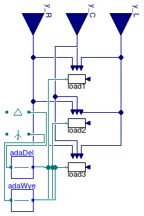
Partial model of a three-phase unbalanced impedance
Information
This model represents a partial interface for a three-phase AC unbalanced impedance.
The model can be configured in order to represent different type of impedances as well as configurations.
The loads can be connected either in wye (Y) or delta (D) configuration.
The parameter loadConn can be used for such a purpose.
The model has three impedances that can be either connected in Y or
D configuration. The parameter loadConn can be used for
such a purpose. The Boolean parameter inductive can be selected
to specify the type of impedance.
The impedances on each phase can be removed using the boolean flags
plugPhase1, plugPhase2, and plugPhase3.
These parameters can be used to generate unbalanced loads.
The values of the impedances are computed starting from the parameters R,
L, and C. Depending on the values of the boolean flag
inductive some of these parameters may be disabled. There are additional
flags use_R_in, use_L_in, and use_C_in that can
be used to specify time varying impedances.
Extends from Buildings.Electrical.Interfaces.PartialPluggableUnbalanced (Partial interface for unbalanced loads).
Parameters
| Type | Name | Default | Description |
|---|---|---|---|
| Boolean | plugPhase1 | true | If true, phase 1 is connected |
| Boolean | plugPhase2 | true | If true, phase 2 is connected |
| Boolean | plugPhase3 | true | If true, phase 3 is connected |
| Impedance | load1 | load1(inductive=inductive, R... | Load 1 |
| Impedance | load2 | load2(inductive=inductive, R... | Load 2 |
| Impedance | load3 | load3(inductive=inductive, R... | Load 3 |
| LoadConnection | loadConn | Buildings.Electrical.Types.L... | Type of load connection (Yg or D) |
| Boolean | inductive | true | If =true the load is inductive, otherwise it is capacitive |
| Resistance | R | 1 | Resistance [Ohm] |
| Inductance | L | 0 | Inductance [H] |
| Capacitance | C | 0 | Capacitance [F] |
| Variable load | |||
| Resistance | |||
| Boolean | use_R_in | false | if true, R is specified by an input |
| Resistance | RMin | 1e-4 | Minimum value of the resistance [Ohm] |
| Resistance | RMax | 1e2 | Maximum value of the resistance [Ohm] |
| Capacitance | |||
| Boolean | use_C_in | false | if true, C is specified by an input |
| Capacitance | CMin | 1e-4 | Minimum value of the capacitance [F] |
| Capacitance | CMax | 1e2 | Maximum value of the capacitance [F] |
| Inductance | |||
| Boolean | use_L_in | false | if true, L is specified by an input |
| Inductance | LMin | 1e-4 | Minimum value of the inductance [H] |
| Inductance | LMax | 1e2 | Maximum value of the inductance [H] |
Connectors
| Type | Name | Description |
|---|---|---|
| input RealInput | y_R | Input that sepecifies variable R |
| input RealInput | y_C | Input that sepecifies variable C |
| input RealInput | y_L | Input that sepecifies variable L |
Modelica definition
 Buildings.Electrical.AC.ThreePhasesUnbalanced.Loads.BaseClasses.BaseLoadCtrl
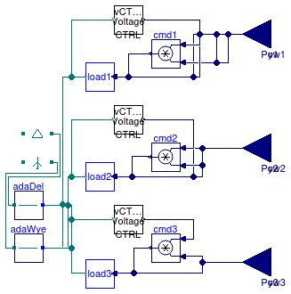
Partial model of a three-phase unbalanced load with voltage controllers
Information
This model represents a partial interface for a three-phase AC unbalanced load.
The loads on each phase can be removed using the boolean flags
plugPhase1, plugPhase2, and plugPhase3.
These parameters can be used to generate unbalanced loads.
The loads can be connected either in wye (Y) or delta (D) configuration.
The parameter loadConn can be used for such a purpose.
Each load model has the option to be controlled by a voltage controller. When enabled, the voltage controller unplugs the load for a certain amount of time if the voltage exceeds a given threshold. Mode information about the voltage controller can be found here.
Extends from Buildings.Electrical.Interfaces.PartialPluggableUnbalanced (Partial interface for unbalanced loads).
Parameters
| Type | Name | Default | Description |
|---|---|---|---|
| Boolean | plugPhase1 | true | If true, phase 1 is connected |
| Boolean | plugPhase2 | true | If true, phase 2 is connected |
| Boolean | plugPhase3 | true | If true, phase 3 is connected |
| LoadConnection | loadConn | Buildings.Electrical.Types.L... | Type of load connection (Yg or D) |
| Load | load1 | load1(redeclare package Phas... | Load 1 |
| Load | load2 | load2(redeclare package Phas... | Load 2 |
| Load | load3 | load3(redeclare package Phas... | Load 3 |
| Modeling assumption | |||
| Boolean | linearized | false | If =true introduce a linearization in the load |
| Load | mode | Buildings.Electrical.Types.L... | Parameters that specifies the mode of the load (e.g., steady state, dynamic, prescribed power consumption, etc.) |
| Nominal conditions | |||
| Power | P_nominal | 0 | Nominal power (negative if consumed, positive if generated) [W] |
| Voltage | V_nominal | Nominal voltage (V_nominal >= 0) [V] | |
| Voltage CTRL | |||
| Boolean | voltageCtrl | false | This flag enables the voltage control |
| Real | vThresh | 0.1 | Threshold that activates voltage ctrl (ratio of nominal voltage) |
| Time | tDelay | 300 | Time to wait before plugging the load again after disconnection [s] |
| Initialization | |||
| InitMode | initMode | Buildings.Electrical.Types.I... | Initialization mode for homotopy operator |
Connectors
| Type | Name | Description |
|---|---|---|
| input RealInput | y1 | Fraction of the nominal power consumed |
| input RealInput | Pow1 | Power consumed [W] |
| input RealInput | y2 | Fraction of the nominal power consumed |
| input RealInput | Pow2 | Power consumed [W] |
| input RealInput | y3 | Fraction of the nominal power consumed |
| input RealInput | Pow3 | Power consumed [W] |
Modelica definition
 Buildings.Electrical.AC.ThreePhasesUnbalanced.Loads.BaseClasses.Impedance
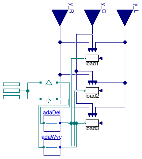
Partial model of a three-phase unbalanced impedance without neutral cable
Information
This model represents a partial interface for a three-phase AC unbalanced impedance without neutral cable.
The model can be configured in order to represent different type of impedances as well as configurations.
The loads can be connected either in wye (Y) or delta (D) configuration.
The parameter loadConn can be used for such a purpose.
The model has three impedances that can be either connected in Y or
Delta configuration. The parameter loadConn can be used for
such a purpose. The Boolean parameter inductive can be selected
to specify the type of impedance.
The impedances on each phase can be removed using the boolean flags
plugPhase1, plugPhase2, and plugPhase3.
These parameters can be used to generate unbalanced loads.
The values of the impedances are computed starting from the parameters R,
L, and C. Depending on the values of the boolean flag
inductive some of these parameters may be disabled. There are additional
flags use_R_in, use_L_in, and use_C_in that can
be used to specify time varying impedances.
Extends from Buildings.Electrical.AC.ThreePhasesUnbalanced.Loads.BaseClasses.BaseImpedance (Partial model of a three-phase unbalanced impedance).
Parameters
| Type | Name | Default | Description |
|---|---|---|---|
| Boolean | plugPhase1 | true | If true, phase 1 is connected |
| Boolean | plugPhase2 | true | If true, phase 2 is connected |
| Boolean | plugPhase3 | true | If true, phase 3 is connected |
| Impedance | load1 | redeclare Buildings.Electric... | Load 1 |
| Impedance | load2 | redeclare Buildings.Electric... | Load 2 |
| Impedance | load3 | redeclare Buildings.Electric... | Load 3 |
| LoadConnection | loadConn | Buildings.Electrical.Types.L... | Type of load connection (Yg or D) |
| Boolean | inductive | true | If =true the load is inductive, otherwise it is capacitive |
| Resistance | R | 1 | Resistance [Ohm] |
| Inductance | L | 0 | Inductance [H] |
| Capacitance | C | 0 | Capacitance [F] |
| Variable load | |||
| Resistance | |||
| Boolean | use_R_in | false | if true, R is specified by an input |
| Resistance | RMin | 1e-4 | Minimum value of the resistance [Ohm] |
| Resistance | RMax | 1e2 | Maximum value of the resistance [Ohm] |
| Capacitance | |||
| Boolean | use_C_in | false | if true, C is specified by an input |
| Capacitance | CMin | 1e-4 | Minimum value of the capacitance [F] |
| Capacitance | CMax | 1e2 | Maximum value of the capacitance [F] |
| Inductance | |||
| Boolean | use_L_in | false | if true, L is specified by an input |
| Inductance | LMin | 1e-4 | Minimum value of the inductance [H] |
| Inductance | LMax | 1e2 | Maximum value of the inductance [H] |
Connectors
| Type | Name | Description |
|---|---|---|
| input RealInput | y_R | Input that sepecifies variable R |
| input RealInput | y_C | Input that sepecifies variable C |
| input RealInput | y_L | Input that sepecifies variable L |
| Terminal_n | terminal | Electrical connector |
Modelica definition
 Buildings.Electrical.AC.ThreePhasesUnbalanced.Loads.BaseClasses.Impedance_N
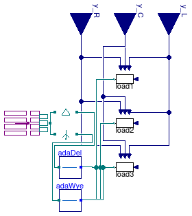
Partial model of a three-phase unbalanced impedance with neutral cable
Information
This model represents a partial interface for a three-phase AC unbalanced impedance with a neutral cable. The current in the neutral cable is computed as the algebraic sum of the currents in the loads.
The model can be configured in order to represent different type of impedances as well as configurations.
The loads can be connected either in wye (Y) or delta (D) configuration.
The parameter loadConn can be used for such a purpose.
The model has three impedances that can be either connected in Y or
Delta configuration. The parameter loadConn can be used for
such a purpose. The Boolean parameter inductive can be selected
to specify the type of impedance.
The impedances on each phase can be removed using the boolean flags
plugPhase1, plugPhase2, and plugPhase3.
These parameters can be used to generate unbalanced loads.
The values of the impedances are computed starting from the parameters R,
L, and C. Depending on the values of the boolean flag
inductive some of these parameters may be disabled. There are additional
flags use_R_in, use_L_in, and use_C_in that can
be used to specify time varying impedances.
Extends from Buildings.Electrical.AC.ThreePhasesUnbalanced.Loads.BaseClasses.BaseImpedance (Partial model of a three-phase unbalanced impedance).
Parameters
| Type | Name | Default | Description |
|---|---|---|---|
| Boolean | plugPhase1 | true | If true, phase 1 is connected |
| Boolean | plugPhase2 | true | If true, phase 2 is connected |
| Boolean | plugPhase3 | true | If true, phase 3 is connected |
| Impedance | load1 | redeclare Buildings.Electric... | Load 1 |
| Impedance | load2 | redeclare Buildings.Electric... | Load 2 |
| Impedance | load3 | redeclare Buildings.Electric... | Load 3 |
| LoadConnection | loadConn | Buildings.Electrical.Types.L... | Type of load connection (Yg or D) |
| Boolean | inductive | true | If =true the load is inductive, otherwise it is capacitive |
| Resistance | R | 1 | Resistance [Ohm] |
| Inductance | L | 0 | Inductance [H] |
| Capacitance | C | 0 | Capacitance [F] |
| Variable load | |||
| Resistance | |||
| Boolean | use_R_in | false | if true, R is specified by an input |
| Resistance | RMin | 1e-4 | Minimum value of the resistance [Ohm] |
| Resistance | RMax | 1e2 | Maximum value of the resistance [Ohm] |
| Capacitance | |||
| Boolean | use_C_in | false | if true, C is specified by an input |
| Capacitance | CMin | 1e-4 | Minimum value of the capacitance [F] |
| Capacitance | CMax | 1e2 | Maximum value of the capacitance [F] |
| Inductance | |||
| Boolean | use_L_in | false | if true, L is specified by an input |
| Inductance | LMin | 1e-4 | Minimum value of the inductance [H] |
| Inductance | LMax | 1e2 | Maximum value of the inductance [H] |
Connectors
| Type | Name | Description |
|---|---|---|
| input RealInput | y_R | Input that sepecifies variable R |
| input RealInput | y_C | Input that sepecifies variable C |
| input RealInput | y_L | Input that sepecifies variable L |
| Terminal4_n | terminal | Electrical connector |
Modelica definition
 Buildings.Electrical.AC.ThreePhasesUnbalanced.Loads.BaseClasses.LoadCtrl
Partial model of a three-phase load with voltage controller without neutral cable
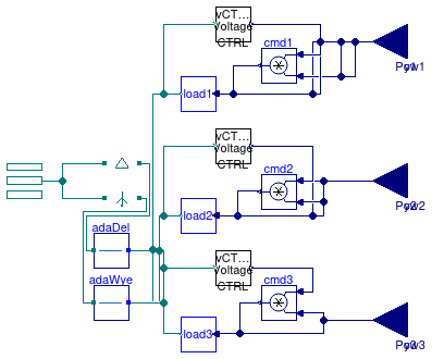
Information
This model represents a partial interface for a three-phase AC unbalanced load without neutral cable.
The loads on each phase can be removed using the boolean flags
plugPhase1, plugPhase2, and plugPhase3.
These parameters can be used to generate unbalanced loads.
The loads can be connected either in wye (Y) or delta (D) configuration.
The parameter loadConn can be used for such a purpose.
Each load model has the option to be controlled by a voltage controller. When enabled, the voltage controller unplugs the load for a certain amount of time if the voltage exceeds a given threshold. Mode information about the voltage controller can be found here.
Extends from Buildings.Electrical.AC.ThreePhasesUnbalanced.Loads.BaseClasses.BaseLoadCtrl (Partial model of a three-phase unbalanced load with voltage controllers).
Parameters
| Type | Name | Default | Description |
|---|---|---|---|
| Boolean | plugPhase1 | true | If true, phase 1 is connected |
| Boolean | plugPhase2 | true | If true, phase 2 is connected |
| Boolean | plugPhase3 | true | If true, phase 3 is connected |
| LoadConnection | loadConn | Buildings.Electrical.Types.L... | Type of load connection (Yg or D) |
| Load | load1 | redeclare Buildings.Electric... | Load 1 |
| Load | load2 | redeclare Buildings.Electric... | Load 2 |
| Load | load3 | redeclare Buildings.Electric... | Load 3 |
| Modeling assumption | |||
| Boolean | linearized | false | If =true introduce a linearization in the load |
| Load | mode | Buildings.Electrical.Types.L... | Parameters that specifies the mode of the load (e.g., steady state, dynamic, prescribed power consumption, etc.) |
| Nominal conditions | |||
| Power | P_nominal | 0 | Nominal power (negative if consumed, positive if generated) [W] |
| Voltage | V_nominal | Nominal voltage (V_nominal >= 0) [V] | |
| Voltage CTRL | |||
| Boolean | voltageCtrl | false | This flag enables the voltage control |
| Real | vThresh | 0.1 | Threshold that activates voltage ctrl (ratio of nominal voltage) |
| Time | tDelay | 300 | Time to wait before plugging the load again after disconnection [s] |
| Initialization | |||
| InitMode | initMode | Buildings.Electrical.Types.I... | Initialization mode for homotopy operator |
Connectors
| Type | Name | Description |
|---|---|---|
| input RealInput | y1 | Fraction of the nominal power consumed |
| input RealInput | Pow1 | Power consumed [W] |
| input RealInput | y2 | Fraction of the nominal power consumed |
| input RealInput | Pow2 | Power consumed [W] |
| input RealInput | y3 | Fraction of the nominal power consumed |
| input RealInput | Pow3 | Power consumed [W] |
| Terminal_n | terminal | Connector for three-phase unbalanced systems without neutral cable |
Modelica definition
 Buildings.Electrical.AC.ThreePhasesUnbalanced.Loads.BaseClasses.LoadCtrl_N
Partial model of a three-phase unbalanced load with voltage controller and neutral cable
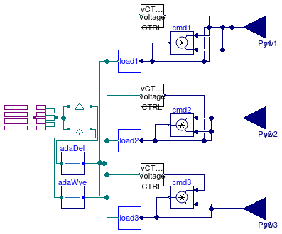
Information
This model represents a partial interface for a three-phase AC unbalanced load with neutral cable. The current in the neutral cable is computed as the algebraic sum of the currents in the loads.
The loads on each phase can be removed using the boolean flags
plugPhase1, plugPhase2, and plugPhase3.
These parameters can be used to generate unbalanced loads.
The loads can be connected either in wye (Y) or delta (D) configuration.
The parameter loadConn can be used for such a purpose.
Each load model has the option to be controlled by a voltage controller. When enabled, the voltage controller unplugs the load for a certain amount of time if the voltage exceeds a given threshold. Mode information about the voltage controller can be found here.
Extends from Buildings.Electrical.AC.ThreePhasesUnbalanced.Loads.BaseClasses.BaseLoadCtrl (Partial model of a three-phase unbalanced load with voltage controllers).
Parameters
| Type | Name | Default | Description |
|---|---|---|---|
| Boolean | plugPhase1 | true | If true, phase 1 is connected |
| Boolean | plugPhase2 | true | If true, phase 2 is connected |
| Boolean | plugPhase3 | true | If true, phase 3 is connected |
| LoadConnection | loadConn | Buildings.Electrical.Types.L... | Type of load connection (Yg or D) |
| Load | load1 | redeclare Buildings.Electric... | Load 1 |
| Load | load2 | redeclare Buildings.Electric... | Load 2 |
| Load | load3 | redeclare Buildings.Electric... | Load 3 |
| Modeling assumption | |||
| Boolean | linearized | false | If =true introduce a linearization in the load |
| Load | mode | Buildings.Electrical.Types.L... | Parameters that specifies the mode of the load (e.g., steady state, dynamic, prescribed power consumption, etc.) |
| Nominal conditions | |||
| Power | P_nominal | 0 | Nominal power (negative if consumed, positive if generated) [W] |
| Voltage | V_nominal | Nominal voltage (V_nominal >= 0) [V] | |
| Voltage CTRL | |||
| Boolean | voltageCtrl | false | This flag enables the voltage control |
| Real | vThresh | 0.1 | Threshold that activates voltage ctrl (ratio of nominal voltage) |
| Time | tDelay | 300 | Time to wait before plugging the load again after disconnection [s] |
| Initialization | |||
| InitMode | initMode | Buildings.Electrical.Types.I... | Initialization mode for homotopy operator |
Connectors
| Type | Name | Description |
|---|---|---|
| input RealInput | y1 | Fraction of the nominal power consumed |
| input RealInput | Pow1 | Power consumed [W] |
| input RealInput | y2 | Fraction of the nominal power consumed |
| input RealInput | Pow2 | Power consumed [W] |
| input RealInput | y3 | Fraction of the nominal power consumed |
| input RealInput | Pow3 | Power consumed [W] |
| Terminal4_n | terminal | Connector for three-phase unbalanced systems with neutral cable |