Buildings.Controls.OBC.Utilities
Package with utility functions
Information
This package contains utility blocks, base classes and validation models for the OpenBuildingControl (OBC) library.
Package Content
| Name | Description |
|---|---|
| Block that outputs the optimal start time for an HVAC system before occupancy | |
| P, PI, PD, and PID controller with output reset and input gains | |
| Package with blocks for setpoint resets | |
| Collection of validation models | |
| Package with base classes |
 Buildings.Controls.OBC.Utilities.OptimalStart
Block that outputs the optimal start time for an HVAC system before occupancy
Information
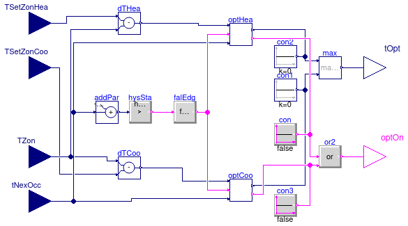
This block predicts the shortest time for an HVAC system to meet the occupied setpoint
prior to the scheduled occupancy. The block requires inputs of zone temperature,
occupied zone setpoint(s) and next occupancy. The two outputs are the optimal start
duration tOpt and the optimal start on signal optOn for
the HVAC system.
The block estimates the thermal mass of a zone using its measured air temperature gradient with respect to time. Once the temperature slope of a zone is known, the optimal start time can be calculated by the difference between the zone temperature and the occupied setpoint divided by the temperature slope, assuming the zone responds as if all thermal mass were concentrated in the room air.
The temperature slope is self-tuned based on past data. The moving
average of the temperature slope of the past nDay days
is calculated and used for
the prediction of the optimal start time in the current day.
Parameters
The parameter nDay is used to compute the moving average of the temperature
slope; the first n days of simulation is therefore used to
initialize the block.
The parameter
tOptMax is the maximum allowed optimal start time.
The block includes two hysteresis parameters uLow and uHigh.
The parameter
uLow is used to determine if the zone temperature reaches
the setpoint. The algorithm assumes that the zone temperature has reached the setpoint if
TSetZonHea-TZon ≤ uLow for a heating system, or
TZon-TSetZonCoo ≤ uLow for a cooling system, where
TSetZonHea
denotes the zone heating setpoint during occupancy, TSetZonCoo
denotes the zone cooling setpoint during occupancy, and TZon denotes the
zone temperature.
The parameter
uHigh is used by the algorithm to determine if there is a need to
start the HVAC system prior to occupancy. If
TSetZonHea-TZon ≤ uHigh for heating case or
TZon-TSetZonCoo ≤ uHigh for cooling case,
then there is no need for the system to start before the occupancy.
The optimal start is only active (i.e., the optimal start on signal optOn
becomes true) if the optimal start time is larger than the parameter
thrOptOn.
Configuration for HVAC systems
The block can be used for heating system only or cooling system only or for both
heating and cooling system.
The two parameters computeHeating and computeCooling are
used to configure the block for these three scenarios.
The block calculates the optimal start time separately for heating and cooling systems. The base class Buildings.Controls.OBC.Utilities.BaseClasses.OptimalStartCalculation is used for the calculation.
Algorithm
The algorithm is as follows:
Step 1: Calculate temeperature slope TSlo
Once the HVAC system is started, a timer records the time duration
Δt for the zone temperature to reach the
setpoint. At the time when the timer starts, the zone temperature TSam1 is sampled.
The temperature slope is
approximated using the equation TSlo = |TSetZonOcc-TSam1|/Δt,
where TSetZonOcc is the occupied zone setpoint. Note that if
Δt is greater than the maximum optimal start time tOptMax,
then tOptMax is used instead of Δt.
This is to avoid corner cases where the setpoint is never reached, e.g., the HVAC
system is undersized, or there is a steady-state error associated with the HVAC control.
Step 2: Calculate temperature slope moving average TSloMa
After computing the temperature slope of each day, the moving average of the
temperature slope TSloMa during the previous nDay days
is calculated. Please refer to
Buildings.Controls.OBC.CDL.Discrete.TriggeredMovingMean for details about
the moving average algorithm.
Step 3: Calculate optimal start time tOpt
Each day at a certain time before the occupancy, the algorithm takes another
sample of the zone temperature, denoted as TSam2. The sample
takes place tOptMax prior to occupancy start time.
The optimal start time is then calculated as tOpt = |TSetZonOcc-TSam2|/TSloMa.
Validation
Validation models can be found in the package Buildings.Controls.OBC.Utilities.Validation.
Parameters
| Type | Name | Default | Description |
|---|---|---|---|
| Real | tOptMax | 10800 | Maximum optimal start time [s] |
| Integer | nDay | 3 | Number of previous days used to compute the optimal start up time |
| Boolean | computeHeating | false | Set to true to compute optimal start for heating |
| Boolean | computeCooling | false | Set to true to compute optimal start for cooling |
| Real | uLow | 0 | Threshold to determine if the zone temperature reaches the occupied setpoint, must be a non-negative number [K] |
| Real | uHigh | 0.5 | Threshold to determine the need to start the HVAC system before occupancy, must be greater than uLow [K] |
| Real | thrOptOn | 60 | Threshold time, optimal start on signal becomes true when tOpt larger than thrOptOn [s] |
Connectors
| Type | Name | Description |
|---|---|---|
| input RealInput | TSetZonHea | Zone heating setpoint temperature during occupancy [K] |
| input RealInput | TZon | Zone temperature [K] |
| input RealInput | TSetZonCoo | Zone cooling setpoint temperature during occupancy [K] |
| input RealInput | tNexOcc | Time until next occupancy [s] |
| output RealOutput | tOpt | Optimal start time duration of HVAC system [s] |
| output BooleanOutput | optOn | Outputs true if the HVAC system remains in the optimal start period |
Modelica definition
 Buildings.Controls.OBC.Utilities.PIDWithInputGains
P, PI, PD, and PID controller with output reset and input gains
Information
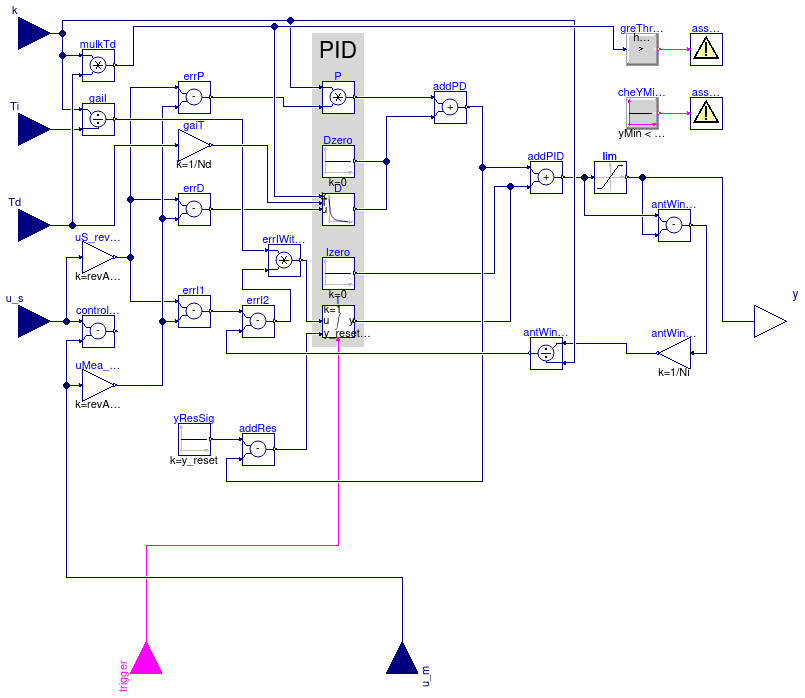
PID controller in the standard form
yu = k/r (e(t) + 1 ⁄ Ti ∫ e(τ) dτ + Td d⁄dt e(t)),
with output reset, where yu is the control signal before output limitation, e(t) = us(t) - um(t) is the control error, with us being the set point and um being the measured quantity, k is the gain, Ti is the time constant of the integral term, Td is the time constant of the derivative term, r is a scaling factor, with default r=1. The scaling factor should be set to the typical order of magnitude of the range of the error e. For example, you may set r=100 to r=1000 if the control input is a pressure of a heating water circulation pump in units of Pascal, or leave r=1 if the control input is a room temperature.
Note that the units of k are the inverse of the units of the control error, while the units of Ti and Td are seconds.
The actual control output is
y = min( ymax, max( ymin, y)),
where ymin and ymax are limits for the control signal.
This block is identical to Buildings.Controls.OBC.CDL.Continuous.PIDWithReset, except that the controller gains k, Ti and Td are inputs rather than parameters.
P, PI, PD, or PID action
Through the parameter controllerType, the controller can be configured
as P, PI, PD or PID controller. The default configuration is PI.
Reverse or direct action
Through the parameter reverseActing, the controller can be configured to
be reverse or direct acting.
The above standard form is reverse acting, which is the default configuration.
For a reverse acting controller, for a constant set point,
an increase in measurement signal u_m decreases the control output signal y
(Montgomery and McDowall, 2008).
Thus,
-
for a heating coil with a two-way valve, leave
reverseActing = true, but -
for a cooling coil with a two-way valve, set
reverseActing = false.
If reverseAction=false, then the error e above is multiplied by -1.
Anti-windup compensation
The controller anti-windup compensation is as follows: Instead of the above basic control law, the implementation is
yu = k (e(t) ⁄ r + 1 ⁄ Ti ∫ (-Δy + e(τ) ⁄ r) dτ + Td ⁄ r d⁄dt e(t)),
where the anti-windup compensation Δy is
Δy = (yu - y) ⁄ (k Ni),
where Ni > 0 is the time constant for the anti-windup compensation. To accelerate the anti-windup, decrease Ni.
Note that the anti-windup term (-Δy + e(τ) ⁄ r) shows that the range of the typical control error r should be set to a reasonable value so that
e(τ) ⁄ r = (us(τ) - um(τ)) ⁄ r
has order of magnitude one, and hence the anti-windup compensation should work well.
Reset of the controller output
Whenever the value of boolean input signal trigger changes from
false to true, the controller output is reset by setting
y to the value of the parameter y_reset.
Approximation of the derivative term
The derivative of the control error d ⁄ dt e(t) is approximated using
d⁄dt x(t) = (e(t)-x(t)) Nd ⁄ Td,
and
d⁄dt e(t) ≈ Nd (e(t)-x(t)),
where x(t) is an internal state.
Guidance for tuning the control gains
The parameters of the controller can be manually adjusted by performing closed loop tests (= controller + plant connected together) and using the following strategy:
- Set very large limits, e.g., set ymax = 1000.
-
Select a P-controller and manually enlarge the parameter
k(the total gain of the controller) until the closed-loop response cannot be improved any more. -
Select a PI-controller and manually adjust the parameters
kandTi(the time constant of the integrator). The first value ofTican be selected such that it is in the order of the time constant of the oscillations occurring with the P-controller. If, e.g., oscillations in the order of 100 seconds occur in the previous step, start withTi=1/100seconds. -
If you want to make the reaction of the control loop faster
(but probably less robust against disturbances and measurement noise)
select a PID-controller and manually adjust parameters
k,Ti,Td(time constant of derivative block). -
Set the limits
yMaxandyMinaccording to your specification. -
Perform simulations such that the output of the PID controller
goes in its limits. Tune
Ni(Ni Ti is the time constant of the anti-windup compensation) such that the input to the limiter block (=lim.u) goes quickly enough back to its limits. IfNiis decreased, this happens faster. IfNiis very large, the anti-windup compensation is not effective and the controller works bad.
References
R. Montgomery and R. McDowall (2008). "Fundamentals of HVAC Control Systems." American Society of Heating Refrigerating and Air-Conditioning Engineers Inc. Atlanta, GA.
Parameters
| Type | Name | Default | Description |
|---|---|---|---|
| SimpleController | controllerType | Buildings.Controls.OBC.CDL.T... | Type of controller |
| Real | r | 1 | Typical range of control error, used for scaling the control error |
| Boolean | reverseActing | true | Set to true for reverse acting, or false for direct acting control action |
| Limits | |||
| Real | yMax | 1 | Upper limit of output |
| Real | yMin | 0 | Lower limit of output |
| Integrator reset | |||
| Real | y_reset | xi_start | Value to which the controller output is reset if the boolean trigger has a rising edge |
| Advanced | |||
| Integrator anti-windup | |||
| Real | Ni | 0.9 | Ni*Ti is time constant of anti-windup compensation |
| Derivative block | |||
| Real | Nd | 10 | The higher Nd, the more ideal the derivative block |
| Initialization | |||
| Real | xi_start | 0 | Initial value of integrator state |
| Real | yd_start | 0 | Initial value of derivative output |
Connectors
| Type | Name | Description |
|---|---|---|
| input RealInput | u_s | Connector for setpoint input signal |
| input RealInput | u_m | Connector for measurement input signal |
| input RealInput | k | Connector for control gain signal |
| input RealInput | Ti | Connector for time constant signal for the integral term [s] |
| input RealInput | Td | Connector for time constant signal for the derivative term [s] |
| output RealOutput | y | Connector for actuator output signal |
| input BooleanInput | trigger | Resets the controller output when trigger becomes true |