Collection of models that illustrate model use and test models
Information
This package contains examples for the use of models that can be found in
Buildings.Airflow.Multizone.
Extends from Modelica.Icons.ExamplesPackage (Icon for packages containing runnable examples).
Package Content
| Name |
Description |
 CO2TransportStep CO2TransportStep
|
Model with transport of CO2 through buoyancy driven flow |
| ChimneyShaftNoVolume
|
Model with chimney effect and a steady-state model of a shaft |
| ChimneyShaftWithVolume
|
Model with chimney effect and a dynamic model of a shaft |
| ClosedDoors
|
Model with three closed doors |
| NaturalVentilation
|
Model with flow reversal due to density difference |
| OneEffectiveAirLeakageArea
|
Model with an effective air leakage area |
| OneOpenDoor
|
Model with one open and one closed door |
| OneRoom
|
Model with one room for the validation of the multizone air exchange models |
| Orifice
|
Model with an orifice |
| PowerLaw
|
Model with powerlaw models |
| PressurizationData
|
Model showing how the 'Powerlaw_1DataPoint' model can be used when data is available from a pressurization test. |
| ReverseBuoyancy
|
Model with four rooms and buoyancy-driven air circulation that reverses direction |
| ReverseBuoyancy3Zones
|
Model with three rooms and buoyancy-driven air circulation that reverses direction |
| TrickleVent
|
Model with a trickle vent modelled using the models with flow based on tabulated data |
| ZonalFlow
|
Model with prescribed air exchange between two volumes |
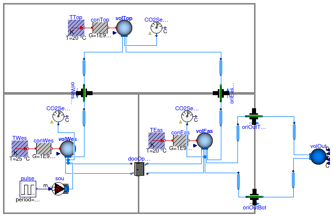
Model with transport of CO2 through buoyancy driven flow
Information
This model is based on
Buildings.Airflow.Multizone.Validation.ThreeRoomsContam.
In addition, a CO2 source has been added to the left room
in the bottom floor.
At initial time, all volumes have zero CO2 concentration.
At t=3600 seconds, CO2 is added to volWes.
As time progresses, the CO2 is transported to
the other rooms, and eventually its concentration decays.
Extends from Buildings.Airflow.Multizone.Validation.ThreeRoomsContam (Model with three rooms for the validation of the multizone air exchange models).
Parameters
| Type | Name | Default | Description |
|---|
| DoorOpen | dooOpeClo | redeclare DoorOpen dooOpeClo... | Door |
Modelica definition
model CO2TransportStep
extends Buildings.Airflow.Multizone.Validation.ThreeRoomsContam(
volWes(nPorts=5),
volTop(nPorts=3),
volEas(nPorts=6));
Buildings.Fluid.Sensors.TraceSubstances CO2SenTop(
redeclare package Medium = Medium)
;
Buildings.Fluid.Sensors.TraceSubstances CO2SenWes(
redeclare package Medium = Medium)
;
Buildings.Fluid.Sensors.TraceSubstances CO2SenEas(
redeclare package Medium = Medium)
;
Modelica.Blocks.Sources.Pulse pulse(
amplitude=8.18E-6,
width=1/24/10,
period=86400,
startTime=3600) ;
Buildings.Fluid.Sources.TraceSubstancesFlowSource sou(
redeclare package Medium = Medium,
use_m_flow_in=true,
nPorts=1) ;
equation
connect(sou.m_flow_in, pulse.y);
connect(sou.ports[1], volWes.ports[4]);
connect(CO2SenWes.port, volWes.ports[5]);
connect(CO2SenTop.port, volTop.ports[3]);
connect(CO2SenEas.port, volEas.ports[6]);
end CO2TransportStep;
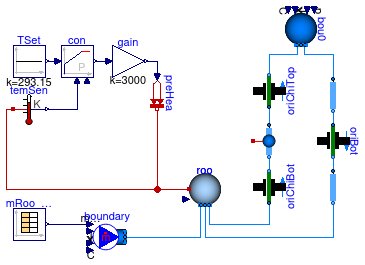
Model with chimney effect and a steady-state model of a shaft

Information
This model demonstrate buoyancy-induced air flow
through a vertical shaft.
On the right, there are two flow paths that are connected
to a volume, which is kept at 20°C through a feedback
controller, and to the ambient, which is at
0°C.
The flow path on the very right consists of an orifice
and two models that compute the pressure difference
Δp
between
the bottom and top of the medium column using Δp=h ρ g,
where
h is the height of the medium column,
ρ is the density of the medium column and
g is the gravity constant.
The top model is parameterized to use the
density from the ambient,
whereas the bottom model is parameterized to use
the density from the room volume, regardless of
the flow direction.
In the other flow path, the model sha
is parameterized to use the density of the inflowing
medium.
Thus, these models can be thought of as a chimney to the left,
and a roof with a leakage on the right. The chimney height starts
1.5 m below the roof, and ends 1.5 m above the roof.
The flow boundary condition of the model
boundary is such that at the start
of the simulation, air flows from boundary
to roo until t=600 seconds. Then, the flow rate
is set to zero until t=1800 seconds.
Since the shaft sha is filled with
20°C air, there is a circulation in the clock-wise
direction; up the shaft, and down the other flow path.
Next, until t=2400 seconds, air is extracted from
the volume roo, and then the flow rate
of boundary is set to zero. Since the
shaft sha is now filed with air at 0°C,
there is a counter clock-wise flow; down the shaft, and
up the other flow path.
Extends from Modelica.Icons.Example (Icon for runnable examples).
Modelica definition
model ChimneyShaftNoVolume
extends Modelica.Icons.Example;
package Medium =
Modelica.Media.Air.SimpleAir;
Buildings.Fluid.MixingVolumes.MixingVolume roo(
V=2.5*5*5,
energyDynamics=Modelica.Fluid.Types.Dynamics.FixedInitial,
T_start=273.15 + 20,
redeclare package Medium = Medium,
m_flow_nominal=0.05,
p_start=101325,
nPorts=3) ;
Buildings.Airflow.Multizone.Orifice oriChiTop(
m=0.5,
redeclare package Medium = Medium,
A=0.01) ;
Buildings.Fluid.Sources.MassFlowSource_T boundary(
redeclare package Medium = Medium,
use_m_flow_in=true,
T=293.15,
nPorts=1) ;
Buildings.Fluid.Sources.Boundary_pT bou0(
redeclare package Medium = Medium,
T=273.15,
nPorts=2) ;
Buildings.Airflow.Multizone.Orifice oriBot(
m=0.5,
redeclare package Medium = Medium,
A=0.01) ;
Modelica.Blocks.Sources.CombiTimeTable mRoo_flow(tableOnFile=false, table=[0,
0.05; 600,0.05; 601,0; 1800,0; 1801,-0.05; 2400,-0.05; 2401,0; 3600,0])
;
MediumColumn staOut(
redeclare package Medium = Medium,
densitySelection=Buildings.Airflow.Multizone.Types.densitySelection.fromTop,
h=1.5) ;
Buildings.Airflow.Multizone.Orifice oriChiBot(
m=0.5,
redeclare package Medium = Medium,
A=0.01) ;
Modelica.Thermal.HeatTransfer.Sources.PrescribedHeatFlow preHea
;
Modelica.Blocks.Continuous.LimPID con(
Td=10,
yMax=1,
yMin=-1,
Ti=60,
controllerType=Modelica.Blocks.Types.SimpleController.P,
k=5) ;
Modelica.Blocks.Sources.Constant TSet(k=293.15) ;
Modelica.Thermal.HeatTransfer.Sensors.TemperatureSensor temSen
;
Modelica.Blocks.Math.Gain gain(k=3000) ;
Buildings.Airflow.Multizone.MediumColumn sha(
redeclare package Medium = Medium,
densitySelection=Buildings.Airflow.Multizone.Types.densitySelection.actual) ;
MediumColumn staIn(
redeclare package Medium = Medium,
densitySelection=Buildings.Airflow.Multizone.Types.densitySelection.fromBottom,
h=1.5) ;
equation
connect(TSet.y, con.u_s);
connect(temSen.T, con.u_m);
connect(gain.u, con.y);
connect(gain.y, preHea.Q_flow);
connect(sha.port_a, oriChiTop.port_a);
connect(sha.port_b, oriChiBot.port_b);
connect(staOut.port_b, oriBot.port_a);
connect(preHea.port, roo.heatPort);
connect(roo.heatPort, temSen.port);
connect(bou0.ports[1], oriChiTop.port_b);
connect(bou0.ports[2], staOut.port_a);
connect(oriBot.port_b, staIn.port_a);
connect(mRoo_flow.y[1], boundary.m_flow_in);
connect(boundary.ports[1], roo.ports[1]);
connect(roo.ports[2], staIn.port_b);
connect(roo.ports[3], oriChiBot.port_a);
end ChimneyShaftNoVolume;
Model with chimney effect and a dynamic model of a shaft
Information
This model is identical to
Buildings.Airflow.Multizone.Examples.ChimneyShaftNoVolume,
except that the chimney model is not steady-state, but rather dynamic
as it contains an air volume. The air volume is approximated
as being well-mixed. (Stratified volumes could be approximated by
using multiple instances of the model sha that are
connected in series.)
Extends from Modelica.Icons.Example (Icon for runnable examples).
Modelica definition
model ChimneyShaftWithVolume
extends Modelica.Icons.Example;
package Medium =
Buildings.Media.Air;
Buildings.Fluid.MixingVolumes.MixingVolume roo(
V=2.5*5*5,
energyDynamics=Modelica.Fluid.Types.Dynamics.FixedInitial,
T_start=273.15 + 20,
redeclare package Medium = Medium,
m_flow_nominal=0.05,
p_start=101325,
nPorts=3) ;
Buildings.Airflow.Multizone.Orifice oriChiTop(
m=0.5,
redeclare package Medium = Medium,
A=0.01) ;
Buildings.Fluid.Sources.MassFlowSource_T boundary(
redeclare package Medium = Medium,
use_m_flow_in=true,
T=293.15,
nPorts=1) ;
Buildings.Fluid.Sources.Boundary_pT bou0(
redeclare package Medium = Medium,
T=273.15,
nPorts=2) ;
Buildings.Airflow.Multizone.Orifice oriBot(
m=0.5,
redeclare package Medium = Medium,
A=0.01) ;
Modelica.Blocks.Sources.CombiTimeTable mRoo_flow(tableOnFile=false, table=[0,
0.05; 600,0.05; 601,0; 1800,0; 1801,-0.05; 2400,-0.05; 2401,0; 3600,0])
;
MediumColumn staOut(
redeclare package Medium = Medium,
densitySelection=Buildings.Airflow.Multizone.Types.densitySelection.fromTop,
h=1.5) ;
Buildings.Airflow.Multizone.Orifice oriChiBot(
m=0.5,
redeclare package Medium = Medium,
A=0.01) ;
Modelica.Thermal.HeatTransfer.Sources.PrescribedHeatFlow preHea
;
Modelica.Blocks.Continuous.LimPID con(
Td=10,
yMax=1,
yMin=-1,
Ti=60,
controllerType=Modelica.Blocks.Types.SimpleController.P,
k=5) ;
Modelica.Blocks.Sources.Constant TSet(k=293.15) ;
Modelica.Thermal.HeatTransfer.Sensors.TemperatureSensor temSen
;
Modelica.Blocks.Math.Gain gain(k=3000) ;
Buildings.Airflow.Multizone.MediumColumnDynamic sha(
redeclare package Medium = Medium,
V=3,
energyDynamics=Modelica.Fluid.Types.Dynamics.FixedInitial)
;
MediumColumn staIn(
redeclare package Medium = Medium,
densitySelection=Buildings.Airflow.Multizone.Types.densitySelection.fromBottom,
h=1.5) ;
equation
connect(TSet.y, con.u_s);
connect(temSen.T, con.u_m);
connect(gain.u, con.y);
connect(gain.y, preHea.Q_flow);
connect(sha.port_a, oriChiTop.port_a);
connect(sha.port_b, oriChiBot.port_b);
connect(staOut.port_b, oriBot.port_a);
connect(preHea.port, roo.heatPort);
connect(roo.heatPort, temSen.port);
connect(bou0.ports[1], oriChiTop.port_b);
connect(bou0.ports[2], staOut.port_a);
connect(oriBot.port_b, staIn.port_a);
connect(mRoo_flow.y[1], boundary.m_flow_in);
connect(boundary.ports[1], roo.ports[1]);
connect(roo.ports[2], staIn.port_b);
connect(roo.ports[3], oriChiBot.port_a);
end ChimneyShaftWithVolume;
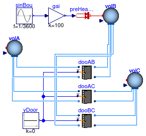
Model with three closed doors
Information
This model consists of three volumes that are connected among
each other through three doors that all have the same geometry.
All doors are closed, but they are not air-tight.
Heat is added and removed from volB which induces
a small air flow through the doors.
This model uses
Buildings.Media.Specialized.Air.PerfectGas
as the medium because
Buildings.Media.Air
does not account for expansion if air the air is heated.
Extends from Modelica.Icons.Example (Icon for runnable examples).
Modelica definition
model ClosedDoors
extends Modelica.Icons.Example;
package Medium =
Buildings.Media.Specialized.Air.PerfectGas;
Buildings.Airflow.Multizone.DoorDiscretizedOperable dooAB(
redeclare package Medium = Medium,
LClo=20*1E-4,
forceErrorControlOnFlow=true) ;
Buildings.Fluid.MixingVolumes.MixingVolume volA(
redeclare package Medium = Medium,
V=2.5*5*5,
nPorts=4,
energyDynamics=Modelica.Fluid.Types.Dynamics.FixedInitial,
m_flow_nominal=0.01) ;
Buildings.Fluid.MixingVolumes.MixingVolume volB(
redeclare package Medium = Medium,
V=2.5*5*5,
nPorts=4,
energyDynamics=Modelica.Fluid.Types.Dynamics.FixedInitial,
m_flow_nominal=0.01) ;
Modelica.Thermal.HeatTransfer.Sources.PrescribedHeatFlow preHeaFlo
;
Modelica.Blocks.Sources.Sine sinBou(f=1/3600)
;
Modelica.Blocks.Math.Gain gai(k=100) ;
Buildings.Fluid.MixingVolumes.MixingVolume volC(
redeclare package Medium = Medium,
V=2.5*5*5,
nPorts=4,
energyDynamics=Modelica.Fluid.Types.Dynamics.FixedInitial,
m_flow_nominal=0.01) ;
Buildings.Airflow.Multizone.DoorDiscretizedOperable dooAC(
redeclare package Medium = Medium,
LClo=20*1E-4,
forceErrorControlOnFlow=true) ;
Modelica.Blocks.Sources.Constant yDoor(k=0) ;
Buildings.Airflow.Multizone.DoorDiscretizedOperable dooBC(
redeclare package Medium = Medium,
LClo=20*1E-4,
forceErrorControlOnFlow=true) ;
equation
connect(gai.y, preHeaFlo.Q_flow);
connect(sinBou.y, gai.u);
connect(yDoor.y, dooAB.y);
connect(yDoor.y, dooAC.y);
connect(yDoor.y, dooBC.y);
connect(preHeaFlo.port, volB.heatPort);
connect(volC.ports[1], dooAC.port_b1);
connect(volC.ports[2], dooAC.port_a2);
connect(volC.ports[3], dooBC.port_b1);
connect(volC.ports[4], dooBC.port_a2);
connect(volB.ports[1], dooAB.port_b1);
connect(volB.ports[2], dooAB.port_a2);
connect(volB.ports[3], dooBC.port_a1);
connect(volB.ports[4], dooBC.port_b2);
connect(volA.ports[1], dooAC.port_b2);
connect(volA.ports[2], dooAC.port_a1);
connect(volA.ports[3], dooAB.port_b2);
connect(volA.ports[4], dooAB.port_a1);
end ClosedDoors;
Model with flow reversal due to density difference
Information
This model illustrates buoyancy-driven natural ventilation between
two volumes of air.
The volume volA can be considered as the volume of a room,
and the volume volOut is parameterized to be very large to emulate
outside air.
The outside air is 20°C and at initial time, the room air is
18°C.
This induces an airflow in counter clock-wise direction. Since
heat is added to the room air volume, its temperature raises above the temperature of the outside, which causes the air flow to reverse its direction.
Extends from Modelica.Icons.Example (Icon for runnable examples).
Modelica definition
model NaturalVentilation
extends Modelica.Icons.Example;
package Medium =
Buildings.Media.Air;
Buildings.Fluid.MixingVolumes.MixingVolume volA(
redeclare package Medium = Medium,
V=2.5*10*5,
energyDynamics=Modelica.Fluid.Types.Dynamics.FixedInitial,
T_start=273.15 + 18,
nPorts=2,
m_flow_nominal=0.001) ;
Buildings.Airflow.Multizone.Orifice oriOutBot(
redeclare package Medium = Medium,
A=0.1,
m=0.5,
dp_turbulent=0.1) ;
Buildings.Airflow.Multizone.MediumColumn colOut(
redeclare package Medium = Medium,
h=3,
densitySelection=Buildings.Airflow.Multizone.Types.densitySelection.fromBottom)
;
Buildings.Airflow.Multizone.Orifice oriOutTop(
redeclare package Medium = Medium,
A=0.1,
m=0.5,
dp_turbulent=0.1) ;
Buildings.Airflow.Multizone.MediumColumn colRooTop(
redeclare package Medium = Medium,
h=3,
densitySelection=Buildings.Airflow.Multizone.Types.densitySelection.fromBottom)
;
Buildings.Fluid.MixingVolumes.MixingVolume volOut(
redeclare package Medium = Medium,
energyDynamics=Modelica.Fluid.Types.Dynamics.FixedInitial,
V=1E10,
T_start=273.15 + 20,
nPorts=2,
m_flow_nominal=0.001) ;
Modelica.Thermal.HeatTransfer.Sources.PrescribedHeatFlow preHeaFlo
;
Modelica.Blocks.Sources.Step q_flow(
height=-100,
offset=100,
startTime=3600) ;
equation
connect(q_flow.y, preHeaFlo.Q_flow);
connect(oriOutBot.port_b, volOut.ports[1]);
connect(preHeaFlo.port, volA.heatPort);
connect(volA.ports[1], oriOutBot.port_a);
connect(volA.ports[2], colRooTop.port_b);
connect(colRooTop.port_a, oriOutTop.port_a);
connect(volOut.ports[2], colOut.port_b);
connect(colOut.port_a, oriOutTop.port_b);
end NaturalVentilation;
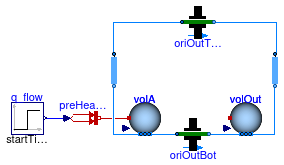
Model with an effective air leakage area
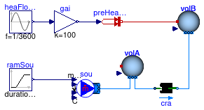
Information
This model consists of a model for an effective air leakage area
that is connected to two air volumes.
Air flows due to the addition of air to the volume volA
and because heat is exchanged with volB.
Extends from Modelica.Icons.Example (Icon for runnable examples).
Modelica definition
model OneEffectiveAirLeakageArea
extends Modelica.Icons.Example;
package Medium =
Buildings.Media.Air;
Buildings.Fluid.MixingVolumes.MixingVolume volA(
redeclare package Medium = Medium,
V=2.5*5*5,
nPorts=2,
energyDynamics=Modelica.Fluid.Types.Dynamics.FixedInitial,
m_flow_nominal=0.01) ;
Buildings.Fluid.MixingVolumes.MixingVolume volB(
redeclare package Medium = Medium,
V=2.5*5*5,
nPorts=1,
energyDynamics=Modelica.Fluid.Types.Dynamics.FixedInitial,
m_flow_nominal=0.01) ;
Modelica.Thermal.HeatTransfer.Sources.PrescribedHeatFlow preHeaFlo
;
Modelica.Blocks.Sources.Sine heaFloBou(f=1/3600)
;
Modelica.Blocks.Math.Gain gai(k=100)
;
Buildings.Airflow.Multizone.EffectiveAirLeakageArea cra(
redeclare package
Medium = Medium, L=20E-4)
;
Buildings.Fluid.Sources.MassFlowSource_T sou(
redeclare package Medium = Medium,
nPorts=1,
use_m_flow_in=true) ;
Modelica.Blocks.Sources.Ramp ramSou(
duration=3600,
height=0.01,
offset=0,
startTime=1800)
;
equation
connect(sou.ports[1], volA.ports[1]);
connect(ramSou.y, sou.m_flow_in);
connect(volB.ports[1], cra.port_b);
connect(volA.ports[2], cra.port_a);
connect(preHeaFlo.port, volB.heatPort);
connect(gai.y, preHeaFlo.Q_flow);
connect(gai.u, heaFloBou.y);
end OneEffectiveAirLeakageArea;
Model with one open and one closed door
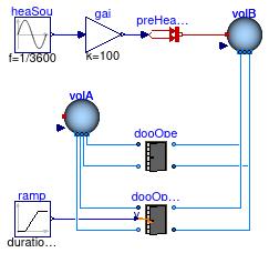
Information
This model consists of two doors with the same geometry.
For t ≤ 1000 seconds, the door dooOpeClo
is closed, and afterwards it is open. The door
dooOpe is always open.
Heat is added to the volume volB, which causes
a density difference between volA and volB.
This density difference induces a bi-directional airflow through both doors.
Both doors have exactly the same bi-directional airflow rates.
Extends from Modelica.Icons.Example (Icon for runnable examples).
Modelica definition
model OneOpenDoor
extends Modelica.Icons.Example;
package Medium =
Modelica.Media.Air.SimpleAir;
Buildings.Airflow.Multizone.DoorDiscretizedOpen dooOpe(
redeclare package Medium = Medium) ;
Buildings.Fluid.MixingVolumes.MixingVolume volA(
redeclare package Medium = Medium,
V=2.5*5*5,
energyDynamics=Modelica.Fluid.Types.Dynamics.FixedInitial,
nPorts=4,
m_flow_nominal=0.01) ;
Buildings.Fluid.MixingVolumes.MixingVolume volB(
redeclare package Medium = Medium,
V=2.5*5*5,
energyDynamics=Modelica.Fluid.Types.Dynamics.FixedInitial,
nPorts=4,
m_flow_nominal=0.01) ;
Modelica.Thermal.HeatTransfer.Sources.PrescribedHeatFlow preHeaFlo
;
Modelica.Blocks.Sources.Sine heaSou(f=1/3600)
;
Modelica.Blocks.Math.Gain gai(k=100)
;
Buildings.Airflow.Multizone.DoorDiscretizedOperable dooOpeClo(
redeclare
package
Medium = Medium, LClo=20*1E-4) ;
Modelica.Blocks.Sources.Ramp ramp(
duration=120,
height=1,
offset=0,
startTime=1000) ;
equation
connect(gai.y, preHeaFlo.Q_flow);
connect(heaSou.y, gai.u);
connect(ramp.y, dooOpeClo.y);
connect(preHeaFlo.port, volB.heatPort);
connect(volA.ports[1], dooOpeClo.port_b2);
connect(volA.ports[2], dooOpeClo.port_a1);
connect(volA.ports[3], dooOpe.port_b2);
connect(volA.ports[4], dooOpe.port_a1);
connect(volB.ports[1], dooOpe.port_b1);
connect(volB.ports[2], dooOpe.port_a2);
connect(volB.ports[3], dooOpeClo.port_b1);
connect(volB.ports[4], dooOpeClo.port_a2);
end OneOpenDoor;
Model with one room for the validation of the multizone air exchange models
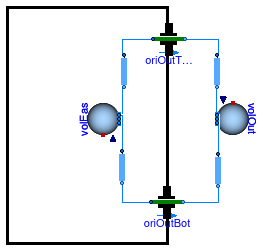
Information
This model has been used to validate buoyancy-driven air flow between two volumes.
The volume volEas is at 20°C and the volume
volOut is at 10°C.
This initial condition induces a clock-wise airflow between the two volumes.
Extends from Modelica.Icons.Example (Icon for runnable examples).
Modelica definition
model OneRoom
extends Modelica.Icons.Example;
package Medium =
Buildings.Media.Air;
Buildings.Fluid.MixingVolumes.MixingVolume volEas(
redeclare package Medium = Medium,
energyDynamics=Modelica.Fluid.Types.Dynamics.FixedInitial,
T_start=273.15 + 20,
V=2.5*5*5,
nPorts=2,
m_flow_nominal=0.001,
massDynamics=Modelica.Fluid.Types.Dynamics.SteadyStateInitial)
;
Buildings.Airflow.Multizone.Orifice oriOutBot(
redeclare package Medium = Medium,
A=0.01,
m=0.5) ;
Buildings.Airflow.Multizone.MediumColumn colOutTop(
redeclare package Medium = Medium,
h=1.5,
densitySelection=Buildings.Airflow.Multizone.Types.densitySelection.fromBottom)
;
Buildings.Airflow.Multizone.Orifice oriOutTop(
redeclare package Medium = Medium,
A=0.01,
m=0.5) ;
Buildings.Airflow.Multizone.MediumColumn colEasInTop(
redeclare package Medium = Medium,
h=1.5,
densitySelection=Buildings.Airflow.Multizone.Types.densitySelection.fromBottom)
;
Buildings.Fluid.MixingVolumes.MixingVolume volOut(
redeclare package Medium = Medium,
energyDynamics=Modelica.Fluid.Types.Dynamics.FixedInitial,
T_start=273.15 + 10,
V=1E12,
p_start=Medium.p_default,
nPorts=2,
m_flow_nominal=0.001)
;
Buildings.Airflow.Multizone.MediumColumn colEasInBot(
redeclare package Medium = Medium,
h=1.5,
densitySelection=Buildings.Airflow.Multizone.Types.densitySelection.fromTop)
;
Buildings.Airflow.Multizone.MediumColumn colOutBot(
redeclare package Medium = Medium,
h=1.5,
densitySelection=Buildings.Airflow.Multizone.Types.densitySelection.fromTop)
;
equation
connect(colEasInTop.port_a, oriOutTop.port_a);
connect(colEasInTop.port_b, volEas.ports[1]);
connect(colEasInBot.port_a, volEas.ports[2]);
connect(colEasInBot.port_b, oriOutBot.port_a);
connect(oriOutBot.port_b, colOutBot.port_b);
connect(colOutBot.port_a, volOut.ports[1]);
connect(colOutTop.port_b, volOut.ports[2]);
connect(colOutTop.port_a, oriOutTop.port_b);
end OneRoom;
Model with an orifice
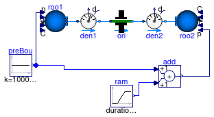
Information
This model demonstrates the use of the orifice model.
The pressure difference across the orifice model changes
between -1 Pascal and +1 Pascal, which
causes air to flow through the orifice.
Extends from Modelica.Icons.Example (Icon for runnable examples).
Modelica definition
model Orifice
extends Modelica.Icons.Example;
package Medium =
Buildings.Media.Air;
Buildings.Airflow.Multizone.Orifice ori(
redeclare package Medium = Medium, A=
0.2) ;
Buildings.Fluid.Sources.Boundary_pT roo1(
redeclare package Medium = Medium,
use_p_in=true,
nPorts=1,
T=278.15) ;
Buildings.Fluid.Sources.Boundary_pT roo2(
redeclare package Medium = Medium,
use_p_in=true,
nPorts=1,
T=293.15) ;
Modelica.Blocks.Sources.Ramp ram(
duration=0.5,
height=2,
offset=-1,
startTime=0.25) ;
Modelica.Blocks.Sources.Constant preBou(k=100000)
;
Modelica.Blocks.Math.Add add ;
Buildings.Fluid.Sensors.DensityTwoPort den1(
redeclare package Medium = Medium,
m_flow_nominal=0.1,
initType=Modelica.Blocks.Types.Init.InitialState) ;
Buildings.Fluid.Sensors.DensityTwoPort den2(
redeclare package Medium = Medium,
m_flow_nominal=0.1,
initType=Modelica.Blocks.Types.Init.InitialState) ;
equation
connect(preBou.y, add.u1);
connect(ram.y, add.u2);
connect(preBou.y, roo1.p_in);
connect(add.y, roo2.p_in);
connect(roo1.ports[1], den1.port_a);
connect(den1.port_b, ori.port_a);
connect(ori.port_b, den2.port_a);
connect(den2.port_b, roo2.ports[1]);
end Orifice;
Model with powerlaw models
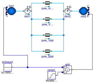
Information
This model demonstrates the use of the 4 PowerLaw models present in the multizone package.
The input data is fit so that all models have equivalent output.
The pressure difference across the models changes
between -1 Pascal and +1 Pascal, which
causes air to flow through the orifice.
Extends from Modelica.Icons.Example (Icon for runnable examples).
Modelica definition
model PowerLaw
extends Modelica.Icons.Example;
package Medium =
Buildings.Media.Air;
Coefficient_m_flow pow_m_flow(
redeclare package Medium = Medium,
m=0.59,
k=3.33e-5) ;
Buildings.Fluid.Sources.Boundary_pT roo1(
redeclare package Medium = Medium,
use_p_in=true,
nPorts=1,
T=278.15) ;
Buildings.Fluid.Sources.Boundary_pT roo2(
redeclare package Medium = Medium,
use_p_in=true,
nPorts=1,
T=293.15) ;
Modelica.Blocks.Sources.Ramp ramp1(
duration=0.5,
height=6,
offset=-3,
startTime=0.25) ;
Modelica.Blocks.Sources.Constant pressure(k=100000) ;
Modelica.Blocks.Math.Add add ;
Buildings.Fluid.Sensors.DensityTwoPort den1(
redeclare package Medium = Medium,
m_flow_nominal=0.1,
tau=0,
initType=Modelica.Blocks.Types.Init.InitialState) ;
Buildings.Fluid.Sensors.DensityTwoPort den2(
redeclare package Medium = Medium,
m_flow_nominal=0.1,
tau=0,
initType=Modelica.Blocks.Types.Init.InitialState) ;
Coefficient_V_flow pow_V_flow(
redeclare package Medium = Medium,
m=0.59,
C=3.33e-5/1.2)
;
Point_m_flow pow_1dat(
redeclare package Medium = Medium,
dpMea_nominal = 50,
m=0.59,
mMea_flow_nominal=1.2/3600)
;
Points_m_flow pow_2dat(
redeclare package Medium = Medium,
dpMea_nominal = {1, 50},
mMea_flow_nominal={0.12, 1.2}/3600)
;
equation
connect(pressure.y, add.u1);
connect(ramp1.y, add.u2);
connect(pressure.y, roo1.p_in);
connect(add.y, roo2.p_in);
connect(roo1.ports[1], den1.port_a);
connect(den1.port_b, pow_m_flow.port_a);
connect(pow_m_flow.port_b, den2.port_a);
connect(den2.port_b, roo2.ports[1]);
connect(den1.port_b, pow_V_flow.port_a);
connect(pow_V_flow.port_b, den2.port_a);
connect(den1.port_b, pow_1dat.port_a);
connect(den1.port_b, pow_2dat.port_a);
connect(pow_1dat.port_b, den2.port_a);
connect(pow_2dat.port_b, den2.port_a);
end PowerLaw;
Model showing how the 'Powerlaw_1DataPoint' model can be used when data is available from a pressurization test.
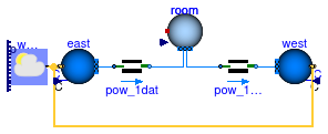
Information
This model illustrates the use of
Buildings.Airflow.Multizone.Point_m_flow
to model
infiltration through the building evelope for a known n50 value (also known as ACH50).
As the n50 value and the building volume is known,
the flow at 50 Pa is known. Dividing this flow accross the entire envelope
(typically surface weighted) and using
Buildings.Airflow.Multizone.Point_m_flow,
the infiltration airflow at lower pressure differences can be modelled.
In this example, the two models each represent 50% of the surface where airflow occured due to the pressurization test.
Extends from Modelica.Icons.Example (Icon for runnable examples).
Parameters
| Type | Name | Default | Description |
|---|
| Real | n50 | 3 | ACH50, air changes at 50 Pa |
Modelica definition
model PressurizationData
extends Modelica.Icons.Example;
package Medium =
Buildings.Media.Air;
parameter Real n50=3 ;
BoundaryConditions.WeatherData.ReaderTMY3 weaDat(
filNam=
Modelica.Utilities.Files.loadResource("modelica://Buildings/Resources/weatherdata/USA_CA_San.Francisco.Intl.AP.724940_TMY3.mos"));
Fluid.Sources.Outside_CpLowRise west(
redeclare package Medium = Medium,
s=5,
azi=Buildings.Types.Azimuth.W,
Cp0=0.6,
nPorts=1) ;
Fluid.Sources.Outside_CpLowRise east(
redeclare package Medium = Medium,
s=5,
azi=Buildings.Types.Azimuth.E,
Cp0=0.6,
nPorts=1) ;
Fluid.MixingVolumes.MixingVolume room(
redeclare package Medium = Medium,
V=2.5*5*5,
nPorts=2,
energyDynamics=Modelica.Fluid.Types.Dynamics.FixedInitial,
m_flow_nominal=0.01) ;
Buildings.Airflow.Multizone.Point_m_flow pow_1dat(
dpMea_nominal(displayUnit="Pa") = 50,
redeclare package Medium = Medium,
m=0.66,
mMea_flow_nominal=0.5*(room.V*n50*1.2))
;
Buildings.Airflow.Multizone.Point_m_flow pow_1dat1(
dpMea_nominal(displayUnit="Pa") = 50,
redeclare package Medium = Medium,
m=0.66,
mMea_flow_nominal=0.5*(room.V*n50*1.2))
;
equation
connect(weaDat.weaBus, west.weaBus);
connect(east.weaBus, weaDat.weaBus);
connect(east.ports[1], pow_1dat.port_a);
connect(pow_1dat.port_b,room. ports[1]);
connect(pow_1dat1.port_a,room. ports[2]);
connect(pow_1dat1.port_b, west.ports[1]);
end PressurizationData;
Model with four rooms and buoyancy-driven air circulation that reverses direction
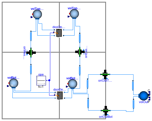
Information
This model is similar than
Buildings.Airflow.Multizone.Validation.ThreeRoomsContam but it has four
instead of three rooms.
The outdoor conditions are held constant at 10°C and
atmospheric pressure.
All four rooms are at different temperatures, with the rooms on the bottom
floor being initially at a higher temperature than the rooms on the top floor.
As time progresses, the temperatures of the two rooms on the respective floors
asymptotically approach each other. The bottom floor eventually cools below
the temperature of the top floor, because the
bottom floor directly exchanges air with the outside.
Extends from Modelica.Icons.Example (Icon for runnable examples).
Modelica definition
model ReverseBuoyancy
extends Modelica.Icons.Example;
package Medium =
Buildings.Media.Air;
Buildings.Fluid.MixingVolumes.MixingVolume volBotEas(
redeclare package Medium = Medium,
energyDynamics=Modelica.Fluid.Types.Dynamics.FixedInitial,
V=2.5*5*5,
T_start=273.15 + 25,
nPorts=5,
m_flow_nominal=0.001) ;
Buildings.Airflow.Multizone.Orifice oriOutBot(
redeclare package Medium = Medium,
m=0.5,
A=0.01,
dp_turbulent=0.1) ;
Buildings.Airflow.Multizone.MediumColumn colOutTop(
redeclare package Medium = Medium,
h=1.5,
densitySelection=Buildings.Airflow.Multizone.Types.densitySelection.fromBottom)
;
Buildings.Airflow.Multizone.Orifice oriOutTop(
redeclare package Medium = Medium,
m=0.5,
A=0.01,
dp_turbulent=0.1) ;
Buildings.Airflow.Multizone.MediumColumn colEasInTop(
redeclare package Medium = Medium,
h=1.5,
densitySelection=Buildings.Airflow.Multizone.Types.densitySelection.fromBottom)
;
Buildings.Airflow.Multizone.MediumColumn colEasInBot(
redeclare package Medium = Medium,
h=1.5,
densitySelection=Buildings.Airflow.Multizone.Types.densitySelection.fromTop)
;
Buildings.Airflow.Multizone.MediumColumn colOutBot(
redeclare package Medium = Medium,
h=1.5,
densitySelection=Buildings.Airflow.Multizone.Types.densitySelection.fromTop)
;
MediumColumn colWesBot(
redeclare package Medium = Medium,
h=1.5,
densitySelection=Buildings.Airflow.Multizone.Types.densitySelection.fromBottom)
;
Buildings.Airflow.Multizone.Orifice oriWesTop(
redeclare package Medium = Medium,
m=0.5,
A=0.01,
dp_turbulent=0.1) ;
Buildings.Airflow.Multizone.MediumColumn colWesTop(
redeclare package Medium = Medium,
h=1.5,
densitySelection=Buildings.Airflow.Multizone.Types.densitySelection.fromTop)
;
Buildings.Airflow.Multizone.DoorDiscretizedOperable dooOpeClo(
redeclare package Medium = Medium,
LClo=20*1E-4,
wOpe=1,
hOpe=2.2,
hA=3/2,
hB=3/2,
CDOpe=0.78,
CDClo=0.78,
nCom=10,
vZer=0.01,
dp_turbulent=0.1) ;
Fluid.Delays.DelayFirstOrder volBotWes(
redeclare package Medium = Medium,
m_flow_nominal=1.2,
energyDynamics=Modelica.Fluid.Types.Dynamics.FixedInitial,
tau=2.5*5*5,
T_start=273.15 + 22,
nPorts=3,
p_start=101325) ;
Modelica.Blocks.Sources.Constant ope(k=1) ;
Buildings.Airflow.Multizone.MediumColumn col1EasBot(
redeclare package Medium = Medium,
h=1.5,
densitySelection=Buildings.Airflow.Multizone.Types.densitySelection.fromBottom)
;
Buildings.Airflow.Multizone.Orifice oriEasTop(
redeclare package Medium = Medium,
m=0.5,
A=0.01,
dp_turbulent=0.1) ;
Buildings.Airflow.Multizone.MediumColumn colEasTop(
redeclare package Medium = Medium,
h=1.5,
densitySelection=Buildings.Airflow.Multizone.Types.densitySelection.fromTop)
;
Buildings.Fluid.MixingVolumes.MixingVolume volTopEas(
redeclare package Medium = Medium,
energyDynamics=Modelica.Fluid.Types.Dynamics.FixedInitial,
V=2.5*5*10,
T_start=273.15 + 21,
nPorts=3,
m_flow_nominal=0.001) ;
Buildings.Fluid.MixingVolumes.MixingVolume volTopWes(
redeclare package Medium = Medium,
energyDynamics=Modelica.Fluid.Types.Dynamics.FixedInitial,
T_start=273.15 + 20,
V=2.5*5*10,
nPorts=3,
m_flow_nominal=0.001) ;
Buildings.Airflow.Multizone.DoorDiscretizedOperable dooOpeCloTop(
redeclare package Medium = Medium,
LClo=20*1E-4,
wOpe=1,
hOpe=2.2,
hA=3/2,
hB=3/2,
CDOpe=0.78,
CDClo=0.78,
nCom=10,
vZer=0.01,
dp_turbulent=0.1) ;
Buildings.Fluid.Sources.Boundary_pT volOut(
redeclare package Medium = Medium,
p=100000,
T=283.15,
nPorts=2) ;
equation
connect(ope.y, dooOpeClo.y);
connect(ope.y, dooOpeCloTop.y);
connect(oriEasTop.port_b, colEasTop.port_b);
connect(oriWesTop.port_b, colWesBot.port_a);
connect(oriWesTop.port_a, colWesTop.port_b);
connect(oriOutBot.port_b, colOutBot.port_b);
connect(colEasInBot.port_b, oriOutBot.port_a);
connect(colEasInTop.port_a, oriOutTop.port_a);
connect(oriOutTop.port_b, colOutTop.port_a);
connect(volBotWes.ports[1], dooOpeClo.port_b2);
connect(volBotWes.ports[2], dooOpeClo.port_a1);
connect(colWesBot.port_b, volBotWes.ports[3]);
connect(volTopWes.ports[1], colWesTop.port_a);
connect(volTopWes.ports[2], dooOpeCloTop.port_b2);
connect(volTopWes.ports[3], dooOpeCloTop.port_a1);
connect(volTopEas.ports[1], dooOpeCloTop.port_b1);
connect(dooOpeCloTop.port_a2, volTopEas.ports[2]);
connect(colEasTop.port_a, volTopEas.ports[3]);
connect(oriEasTop.port_a, col1EasBot.port_a);
connect(dooOpeClo.port_b1, volBotEas.ports[1]);
connect(dooOpeClo.port_a2, volBotEas.ports[2]);
connect(colEasInBot.port_a, volBotEas.ports[3]);
connect(colEasInTop.port_b, volBotEas.ports[4]);
connect(col1EasBot.port_b, volBotEas.ports[5]);
connect(colOutBot.port_a, volOut.ports[1]);
connect(colOutTop.port_b, volOut.ports[2]);
end ReverseBuoyancy;
Model with three rooms and buoyancy-driven air circulation that reverses direction
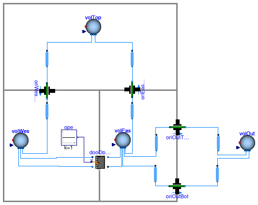
Information
This model is similar than
Buildings.Airflow.Multizone.Validation.ThreeRoomsContam.
However, the initial temperatures are such that at the start of the
simulation, the flow direction between the three rooms reverses direction.
At the start of the simulation,
the outdoor temperature is 15°C,
and the temperatures of the volumes are
20°C at the top,
22°C at the bottom west and
25°C at the bottom east.
Thus, initially there is a net flow circulation in the counter-clock
direction.
Because the volume on the east exchanges air with the outside,
it cools down fast. Once it cooled down sufficiently,
the flow direction between the three rooms reverses
because the air in the bottom east is heaviest.
Extends from Modelica.Icons.Example (Icon for runnable examples).
Modelica definition
model ReverseBuoyancy3Zones
extends Modelica.Icons.Example;
package Medium =
Buildings.Media.Air;
Buildings.Fluid.MixingVolumes.MixingVolume volEas(
redeclare package Medium = Medium,
energyDynamics=Modelica.Fluid.Types.Dynamics.FixedInitial,
V=2.5*5*5,
T_start=273.15 + 25,
nPorts=5,
m_flow_nominal=0.001) ;
Buildings.Airflow.Multizone.Orifice oriOutBot(
redeclare package Medium = Medium,
m=0.5,
A=0.01,
dp_turbulent=0.1) ;
Buildings.Airflow.Multizone.MediumColumn colOutTop(
redeclare package Medium = Medium,
h=1.5,
densitySelection=Buildings.Airflow.Multizone.Types.densitySelection.fromBottom)
;
Buildings.Airflow.Multizone.Orifice oriOutTop(
redeclare package Medium = Medium,
m=0.5,
A=0.01,
dp_turbulent=0.1) ;
Buildings.Airflow.Multizone.MediumColumn colEasInTop(
redeclare package Medium = Medium,
h=1.5,
densitySelection=Buildings.Airflow.Multizone.Types.densitySelection.fromBottom)
;
Buildings.Fluid.MixingVolumes.MixingVolume volOut(
redeclare package Medium = Medium,
energyDynamics=Modelica.Fluid.Types.Dynamics.FixedInitial,
V=1E12,
T_start=273.15 + 15,
nPorts=2,
m_flow_nominal=0.001) ;
Buildings.Airflow.Multizone.MediumColumn colEasInBot(
redeclare package Medium = Medium,
h=1.5,
densitySelection=Buildings.Airflow.Multizone.Types.densitySelection.fromTop)
;
Buildings.Airflow.Multizone.MediumColumn colOutBot(
redeclare package Medium = Medium,
h=1.5,
densitySelection=Buildings.Airflow.Multizone.Types.densitySelection.fromTop)
;
Buildings.Airflow.Multizone.MediumColumn colWesBot(
redeclare package Medium = Medium,
h=1.5,
densitySelection=Buildings.Airflow.Multizone.Types.densitySelection.fromBottom)
;
Buildings.Airflow.Multizone.Orifice oriWesTop(
redeclare package Medium = Medium,
m=0.5,
A=0.01,
dp_turbulent=0.1) ;
Buildings.Airflow.Multizone.MediumColumn colWesTop(
redeclare package Medium = Medium,
h=1.5,
densitySelection=Buildings.Airflow.Multizone.Types.densitySelection.fromTop)
;
Buildings.Airflow.Multizone.DoorDiscretizedOperable dooOpeClo(
redeclare package Medium = Medium,
LClo=20*1E-4,
wOpe=1,
hOpe=2.2,
hA=3/2,
hB=3/2,
CDOpe=0.78,
CDClo=0.78,
nCom=10,
vZer=0.01,
dp_turbulent=0.1) ;
Modelica.Blocks.Sources.Constant ope(k=1) ;
Buildings.Airflow.Multizone.MediumColumn col1EasBot(
redeclare package Medium = Medium,
h=1.5,
densitySelection=Buildings.Airflow.Multizone.Types.densitySelection.fromBottom)
;
Buildings.Airflow.Multizone.Orifice oriEasTop(
redeclare package Medium = Medium,
m=0.5,
A=0.01,
dp_turbulent=0.1) ;
Buildings.Airflow.Multizone.MediumColumn colEasTop(
redeclare package Medium = Medium,
h=1.5,
densitySelection=Buildings.Airflow.Multizone.Types.densitySelection.fromTop)
;
Buildings.Fluid.MixingVolumes.MixingVolume volTop(
redeclare package Medium = Medium,
energyDynamics=Modelica.Fluid.Types.Dynamics.FixedInitial,
T_start=273.15 + 20,
m_flow_nominal=0.001,
V=2.5*10*10,
nPorts=2) ;
Buildings.Fluid.MixingVolumes.MixingVolume volWes(
redeclare package Medium = Medium,
energyDynamics=Modelica.Fluid.Types.Dynamics.FixedInitial,
V=2.5*5*5,
T_start=273.15 + 22,
nPorts=3,
m_flow_nominal=0.001) ;
equation
connect(dooOpeClo.port_b2, volWes.ports[1]);
connect(dooOpeClo.port_a1, volWes.ports[2]);
connect(dooOpeClo.port_b1, volEas.ports[1]);
connect(dooOpeClo.port_a2, volEas.ports[2]);
connect(colWesTop.port_b, oriWesTop.port_a);
connect(oriWesTop.port_b, colWesBot.port_a);
connect(colWesBot.port_b, volWes.ports[3]);
connect(colEasTop.port_b, oriEasTop.port_b);
connect(oriEasTop.port_a, col1EasBot.port_a);
connect(colEasInBot.port_a, volEas.ports[3]);
connect(colEasInTop.port_b, volEas.ports[4]);
connect(col1EasBot.port_b, volEas.ports[5]);
connect(colOutTop.port_b, volOut.ports[1]);
connect(volOut.ports[2], colOutBot.port_a);
connect(colOutBot.port_b, oriOutBot.port_b);
connect(oriOutBot.port_a, colEasInBot.port_b);
connect(colEasInTop.port_a, oriOutTop.port_a);
connect(oriOutTop.port_b, colOutTop.port_a);
connect(ope.y, dooOpeClo.y);
connect(colWesTop.port_a, volTop.ports[1]);
connect(colEasTop.port_a, volTop.ports[2]);
end ReverseBuoyancy3Zones;
Model with a trickle vent modelled using the models with flow based on tabulated data
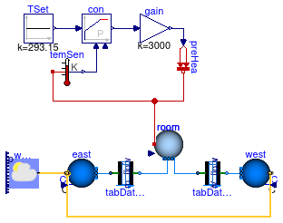
Information
This model illustrates the use of the models
Buildings.Airflow.Multizone.Table_V_flow
and
Buildings.Airflow.Multizone.Table_m_flow
to model self regulating inlet vents.
The models are connected to a common volume that emulates a room on one side and
to outside conditions on the other side (east and west orientation respectively).
Extends from Modelica.Icons.Example (Icon for runnable examples).
Modelica definition
model TrickleVent
extends Modelica.Icons.Example;
package Medium =
Buildings.Media.Air;
BoundaryConditions.WeatherData.ReaderTMY3 weaDat(
filNam=
Modelica.Utilities.Files.loadResource(
"modelica://Buildings/Resources/weatherdata/USA_CA_San.Francisco.Intl.AP.724940_TMY3.mos"))
;
Fluid.Sources.Outside_CpLowRise west(
redeclare package Medium = Medium,
s=5,
azi=Buildings.Types.Azimuth.W,
Cp0=0.6,
nPorts=1) ;
Fluid.Sources.Outside_CpLowRise east(
redeclare package Medium = Medium,
s=5,
azi=Buildings.Types.Azimuth.E,
Cp0=0.6,
nPorts=1) ;
Fluid.MixingVolumes.MixingVolume room(
redeclare package Medium = Medium,
V=2.5*5*5,
nPorts=2,
energyDynamics=Modelica.Fluid.Types.Dynamics.FixedInitial,
m_flow_nominal=0.01) ;
Modelica.Thermal.HeatTransfer.Sources.PrescribedHeatFlow preHea
;
Modelica.Blocks.Continuous.LimPID con(
Td=10,
yMax=1,
yMin=-1,
Ti=60,
controllerType=Modelica.Blocks.Types.SimpleController.P,
k=5) ;
Modelica.Blocks.Sources.Constant TSet(k=293.15) ;
Modelica.Thermal.HeatTransfer.Sensors.TemperatureSensor temSen
;
Modelica.Blocks.Math.Gain gain(k=3000) ;
Buildings.Airflow.Multizone.Table_m_flow tabDat_m_flow(
redeclare package Medium = Medium,
dpMea_nominal = {-50, -25, -10, -5, -3, -2, -1, 0, 1, 2, 3, 4.5, 50},
mMea_flow_nominal = {-0.08709, -0.06158, -0.03895, -0.02754, -0.02133, -0.01742, -0.01232, 0, 0.01232, 0.01742, 0.02133, 0.02613, 0.02614})
;
Buildings.Airflow.Multizone.Table_V_flow tabDat_V_flow(
redeclare package Medium = Medium,
dpMea_nominal = {-50, -25, -10, -5, -3, -2, -1, 0, 1, 2, 3, 4.5, 50},
VMea_flow_nominal = {-0.104508, -0.073896, -0.04674, -0.033048, -0.025596, -0.020904, -0.014784, 0, 0.014784, 0.020904, 0.025596, 0.031356, 0.031368})
;
equation
connect(weaDat.weaBus, west.weaBus);
connect(east.weaBus, weaDat.weaBus);
connect(TSet.y,con. u_s);
connect(temSen.T,con. u_m);
connect(gain.u,con. y);
connect(gain.y,preHea. Q_flow);
connect(room.heatPort, temSen.port);
connect(preHea.port,room. heatPort);
connect(east.ports[1], tabDat_m_flow.port_a);
connect(tabDat_m_flow.port_b,room. ports[1]);
connect(tabDat_V_flow.port_a,room. ports[2]);
connect(tabDat_V_flow.port_b, west.ports[1]);
end TrickleVent;
Model with prescribed air exchange between two volumes
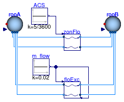
Information
This example illustrates the use of the models that
exchange a prescribed flow rate between the
volumes that are attached to it.
The block ACS prescribes the air exchange rate to
5 air changes per hour.
The instance zonFlo takes as an input the air change per seconds,
and the instance floExc takes as inputs the mass flow rate.
For both instances, the air flows from
rooA to rooB, and
from rooB to rooA.
Extends from Modelica.Icons.Example (Icon for runnable examples).
Parameters
| Type | Name | Default | Description |
|---|
| Volume | volA | 100 | Volume of room A [m3] |
| Volume | volB | 1 | Volume of room B [m3] |
Modelica definition
model ZonalFlow
extends Modelica.Icons.Example;
package Medium =
Buildings.Media.Air;
parameter Modelica.Units.SI.Volume volA=100 ;
parameter Modelica.Units.SI.Volume volB=1 ;
Buildings.Fluid.MixingVolumes.MixingVolume rooA(
V=volA,
redeclare package Medium = Medium,
X_start={0.015,0.985},
T_start=303.15,
nPorts=4,
m_flow_nominal=0.001,
energyDynamics=Modelica.Fluid.Types.Dynamics.FixedInitial) ;
Buildings.Fluid.MixingVolumes.MixingVolume rooB(
V=volB,
redeclare package Medium = Medium,
X_start={0.01,0.99},
T_start=293.15,
nPorts=4,
m_flow_nominal=0.001,
energyDynamics=Modelica.Fluid.Types.Dynamics.FixedInitial) ;
Modelica.Blocks.Sources.Constant ACS(k=5/3600) ;
ZonalFlow_ACS zonFlo(
redeclare package Medium = Medium,
V=
min(volA, volB))
;
Modelica.Blocks.Sources.Constant m_flow(k=0.02) ;
ZonalFlow_m_flow floExc(
redeclare package Medium = Medium)
;
equation
connect(rooA.ports[1], zonFlo.port_a1);
connect(zonFlo.port_b1, rooB.ports[1]);
connect(zonFlo.port_b2, rooA.ports[2]);
connect(zonFlo.port_a2, rooB.ports[2]);
connect(zonFlo.ACS, ACS.y);
connect(floExc.mAB_flow, m_flow.y);
connect(m_flow.y, floExc.mBA_flow);
connect(floExc.port_a1, rooA.ports[3]);
connect(floExc.port_b1, rooB.ports[3]);
connect(floExc.port_a2, rooB.ports[4]);
connect(floExc.port_b2, rooA.ports[4]);
end ZonalFlow;
 Buildings.Airflow.Multizone.Examples.CO2TransportStep