Package with example models
Information
This package contains examples for the use of models that can be found in
Buildings.Electrical.AC.OnePhase.Loads.
Extends from Modelica.Icons.ExamplesPackage (Icon for packages containing runnable examples).
Package Content
| Name |
Description |
 DynamicLoads DynamicLoads
|
Example that illustrates the use of dynamic loads |
| ParallelLoads
|
Example that illustrates the use of the load models at constant voltage |
| ParallelResistors
|
Example that illustrates the use of the load models at constant voltage |
| TestImpedance
|
Example that illustrates the use of the impedances |
| ThreePhases
|
Examples that illustrates how to replicate a three-phase balanced system |
| VariableImpedance
|
Example that illustrates how using variable impedances |
Example that illustrates the use of dynamic loads
Information
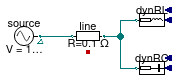
This model compares two dynamic load models that use the dynamic
phasors.
The loads at nominal conditions should consume an active power equal
to 1.2 kW. Because of the line resistance the voltage at the load is
attenuated and they consume less power.
As expected the real part of the current vector drawn by the loads are
the same while the complex parts have opposite signs.
Extends from Modelica.Icons.Example (Icon for runnable examples).
Modelica definition
model DynamicLoads
extends Modelica.Icons.Example;
Buildings.Electrical.AC.OnePhase.Sources.FixedVoltage source(
f=60,
V=120) ;
Buildings.Electrical.AC.OnePhase.Loads.Capacitive dynRC(
pf=0.8,
mode=Buildings.Electrical.Types.Load.FixedZ_dynamic,
P_nominal=-1200,
V_nominal=120) ;
Buildings.Electrical.AC.OnePhase.Lines.TwoPortResistance line(R=0.1)
;
Buildings.Electrical.AC.OnePhase.Loads.Inductive dynRL(
pf=0.8,
mode=Buildings.Electrical.Types.Load.FixedZ_dynamic,
P_nominal=-1200,
V_nominal=120) ;
equation
connect(source.terminal, line.terminal_n);
connect(line.terminal_p, dynRC.terminal);
connect(dynRL.terminal, line.terminal_p);
end DynamicLoads;
Example that illustrates the use of the load models at constant voltage
Information
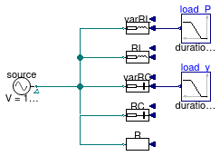
This model illustrates the use of the load models.
The first two lines are inductive loads, followed by two capacitive loads and a resistive load.
The inductive load varRL and the capacitive load varRC
have a variable load specified by the inputs Pow and y
respectively.
All the loads have a nominal power of 1kW, and varRL is the only one
that at t=0 produces power 1kW and as the time increases it start to
consume up to 1kW.
Extends from Modelica.Icons.Example (Icon for runnable examples).
Modelica definition
model ParallelLoads
extends Modelica.Icons.Example;
Buildings.Electrical.AC.OnePhase.Loads.Inductive varRL(
mode=Buildings.Electrical.Types.Load.VariableZ_P_input,
linearized=false,
V_nominal=120) ;
Buildings.Electrical.AC.OnePhase.Sources.FixedVoltage source(f=60, V=120)
;
Modelica.Blocks.Sources.Ramp load_y(duration=0.5, startTime=0.2)
;
Buildings.Electrical.AC.OnePhase.Loads.Inductive RL(
P_nominal=-1e3,
linearized=false,
V_nominal=120) ;
Buildings.Electrical.AC.OnePhase.Loads.Capacitive varRC(mode=Buildings.Electrical.Types.Load.VariableZ_y_input,
P_nominal=-1e3,
linearized=false,
V_nominal=120) ;
Buildings.Electrical.AC.OnePhase.Loads.Capacitive RC(mode=Buildings.Electrical.Types.Load.FixedZ_steady_state,
P_nominal=-1e3,
linearized=false,
V_nominal=120) ;
Buildings.Electrical.AC.OnePhase.Loads.Resistive R(
P_nominal=-1e3,
mode=Buildings.Electrical.Types.Load.FixedZ_steady_state,
linearized=false,
V_nominal=120) ;
Modelica.Blocks.Sources.Ramp load_P(
startTime=0.2,
duration=0.5,
height=-2000,
offset=1000) ;
equation
connect(source.terminal, varRL.terminal);
connect(source.terminal, RL.terminal);
connect(source.terminal, varRC.terminal);
connect(source.terminal, R.terminal);
connect(RC.terminal, R.terminal);
connect(load_y.y, varRC.y);
connect(load_P.y, varRL.Pow);
end ParallelLoads;
Example that illustrates the use of the load models at constant voltage
Information
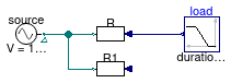
This model compares two resistive loads. Model R consumes or produces
a variable amount of power, while model R1 consumes a fixed power.
At time t=0 R and R1 consumes the same amount of power
while at t=1 R produces the same power consumed by R1.
Extends from Modelica.Icons.Example (Icon for runnable examples).
Modelica definition
model ParallelResistors
extends Modelica.Icons.Example;
Buildings.Electrical.AC.OnePhase.Sources.FixedVoltage
source(f=60, V=120) ;
Modelica.Blocks.Sources.Ramp load(duration=0.5, startTime=0.2,
height=2400,
offset=-1200) ;
Buildings.Electrical.AC.OnePhase.Loads.Resistive R(
mode=Buildings.Electrical.Types.Load.VariableZ_P_input,
V_nominal=120) ;
Buildings.Electrical.AC.OnePhase.Loads.Resistive R1(
mode=Buildings.Electrical.Types.Load.FixedZ_steady_state, P_nominal=-1.2e3,
V_nominal=120) ;
equation
connect(source.terminal, R.terminal);
connect(load.y, R.Pow);
connect(source.terminal, R1.terminal);
end ParallelResistors;
Example that illustrates the use of the impedances
Information
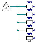
This model shows how to use the impedance model in different configurations:
- Resistive (model
Z3)
- Inductive (model
Z1)
- Capacitive (model
Z2)
- Resistive-Inductive (model
Z4)
- Resistive-Capacitive (model
Z5)
Extends from Modelica.Icons.Example (Icon for runnable examples).
Modelica definition
model TestImpedance
extends Modelica.Icons.Example;
Buildings.Electrical.AC.OnePhase.Sources.FixedVoltage V(f=60, V=120);
Buildings.Electrical.AC.OnePhase.Loads.Impedance Z1(R=0,
inductive=true,
L=1/(2*Modelica.Constants.pi*60)) ;
Buildings.Electrical.AC.OnePhase.Loads.Impedance Z2(R=0,
inductive=false,
C=1/(2*Modelica.Constants.pi*60)) ;
Buildings.Electrical.AC.OnePhase.Loads.Impedance Z3(R=1)
;
Buildings.Electrical.AC.OnePhase.Loads.Impedance Z4(
R=1,
L=1/(2*Modelica.Constants.pi*60)) ;
Buildings.Electrical.AC.OnePhase.Loads.Impedance Z5(
R=1,
inductive=false,
C=1/(2*Modelica.Constants.pi*60)) ;
equation
connect(V.terminal, Z1.terminal);
connect(V.terminal, Z2.terminal);
connect(V.terminal, Z3.terminal);
connect(V.terminal, Z4.terminal);
connect(V.terminal, Z5.terminal);
end TestImpedance;
Examples that illustrates how to replicate a three-phase balanced system
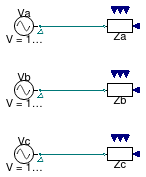
Information
This model shows how a balanced three phase system can be represented with three
independent single phase circuits.
Extends from Modelica.Icons.Example (Icon for runnable examples).
Modelica definition
model ThreePhases
extends Modelica.Icons.Example;
Buildings.Electrical.AC.OnePhase.Sources.FixedVoltage Va(
definiteReference=true,
f=60,
V=120) ;
Buildings.Electrical.AC.OnePhase.Loads.Impedance Za(
inductive=true,
L=1/(2*Modelica.Constants.pi*60),
R=12) ;
Buildings.Electrical.AC.OnePhase.Sources.FixedVoltage Vb(
definiteReference=true, phiSou=-2.0943951023932,
f=60,
V=120) ;
Buildings.Electrical.AC.OnePhase.Loads.Impedance Zb(
inductive=true,
L=1/(2*Modelica.Constants.pi*60),
R=12) ;
Buildings.Electrical.AC.OnePhase.Sources.FixedVoltage Vc(
definiteReference=true, phiSou=2.0943951023932,
f=60,
V=120) ;
Buildings.Electrical.AC.OnePhase.Loads.Impedance Zc(
inductive=true,
L=1/(2*Modelica.Constants.pi*60),
R=12) ;
equation
connect(Va.terminal, Za.terminal);
connect(Vb.terminal, Zb.terminal);
connect(Vc.terminal, Zc.terminal);
end ThreePhases;
Example that illustrates how using variable impedances
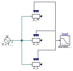
Information
This model shows how to vary the resistance,
capacitance or inductance of an impedance model.
Extends from Modelica.Icons.Example (Icon for runnable examples).
Modelica definition
model VariableImpedance
extends Modelica.Icons.Example;
Buildings.Electrical.AC.OnePhase.Sources.FixedVoltage V(f=60, V=120)
;
Buildings.Electrical.AC.OnePhase.Loads.Impedance Z_L(
R=0,
inductive=true,
L=1/(2*Modelica.Constants.pi*60),
use_L_in=true,
LMin=1/(2*Modelica.Constants.pi*60),
LMax=2/(2*Modelica.Constants.pi*60)) ;
Buildings.Electrical.AC.OnePhase.Loads.Impedance Z_C(
R=0,
inductive=false,
C=1/(2*Modelica.Constants.pi*60),
use_C_in=true,
CMin=1/(2*Modelica.Constants.pi*60),
CMax=2/(2*Modelica.Constants.pi*60)) ;
Buildings.Electrical.AC.OnePhase.Loads.Impedance Z_R(
R=1,
RMin=1,
RMax=2,
use_R_in=true,
L=0) ;
Modelica.Blocks.Sources.Ramp load(duration=0.5, startTime=0.2,
height=1,
offset=0) ;
equation
connect(V.terminal, Z_L.terminal);
connect(V.terminal, Z_C.terminal);
connect(V.terminal, Z_R.terminal);
connect(load.y, Z_R.y_R);
connect(load.y, Z_C.y_C);
connect(load.y, Z_L.y_L);
end VariableImpedance;
 Buildings.Electrical.AC.OnePhase.Loads.Examples.DynamicLoads