Buildings.Fluid.Geothermal.Boreholes.BaseClasses
Base classes for Borehole
Information
This package contains base classes that are used to construct the models in Buildings.Fluid.Geothermal.Boreholes.
Extends from Modelica.Icons.BasesPackage (Icon for packages containing base classes).
Package Content
| Name | Description |
|---|---|
| Vertical segment of a borehole | |
| class used to create the external object: ExtendableArray | |
| Internal part of a borehole | |
| Prescribed temperature at the outer boundary of a single U tube borehole | |
| Thermal resistance between the fluid and the tube | |
| Store the value u at the element n in the external object, and return the value of the element i | |
| Power series used to compute far-field temperature | |
| Thermal resistances for single U-tube | |
| Calculate the temperature drop of the soil at the external boundary of the cylinder | |
| Example models to test base classes |
 Buildings.Fluid.Geothermal.Boreholes.BaseClasses.BoreholeSegment
Vertical segment of a borehole
Information
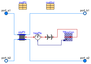
Horizontal layer that is used to model a U-tube borehole heat exchanger. This model combines three models, each simulating a different aspect of a borehole heat exchanger.
The instance pipFil computes the heat transfer in the pipes and the filling material.
This computation is done using the model
Buildings.Fluid.Geothermal.Boreholes.BaseClasses.HexInternalElement.
The instance soi computes transient and steady state heat transfer in the soil using a vertical cylinder.
The computation is done using the model
Buildings.HeatTransfer.Conduction.SingleLayerCylinder.
The model TBouCon computes the far-field temperature boundary condition,
i.e., the temperature at the outer
surface of the above cylindrical heat transfer computation.
The computation is done using the model
Buildings.Fluid.Geothermal.Boreholes.BaseClasses.SingleUTubeBoundaryCondition.
Extends from Buildings.Fluid.Interfaces.PartialFourPortInterface (Partial model transporting fluid between two ports without storing mass or energy), Buildings.Fluid.Interfaces.TwoPortFlowResistanceParameters (Parameters for flow resistance for models with two ports), Buildings.Fluid.Interfaces.LumpedVolumeDeclarations (Declarations for lumped volumes).
Parameters
| Type | Name | Default | Description |
|---|---|---|---|
| replaceable package Medium1 | PartialMedium | Medium 1 in the component | |
| replaceable package Medium2 | PartialMedium | Medium 2 in the component | |
| replaceable package Medium | PartialMedium | Medium in the component | |
| Radius | rBor | 0.1 | Radius of the borehole [m] |
| Height | hSeg | Height of the element [m] | |
| Length | xC | 0.05 | Shank spacing, defined as the distance between the center of a pipe and the center of the borehole [m] |
| Nominal condition | |||
| MassFlowRate | m1_flow_nominal | m_flow_nominal | Nominal mass flow rate [kg/s] |
| MassFlowRate | m2_flow_nominal | m_flow_nominal | Nominal mass flow rate [kg/s] |
| PressureDifference | dp_nominal | Pressure difference [Pa] | |
| MassFlowRate | m_flow_nominal | Nominal mass flow rate [kg/s] | |
| Soil | |||
| Generic | matSoi | redeclare parameter Building... | Thermal properties of soil |
| Radius | rExt | 3 | Radius of the soil used for the external boundary condition [m] |
| Temperature | TExt_start | 283.15 | Initial far field temperature [K] |
| Integer | nSta | 10 | Number of state variables in the soil |
| Time | samplePeriod | 604800 | Sample period for the external boundary condition [s] |
| Filling material | |||
| Generic | matFil | redeclare parameter Building... | Thermal properties of the filling material |
| Temperature | TFil_start | 283.15 | Initial temperature of the filling material [K] |
| Tubes | |||
| Radius | rTub | 0.02 | Radius of the tubes [m] |
| ThermalConductivity | kTub | 0.5 | Thermal conductivity of the tubes [W/(m.K)] |
| Length | eTub | 0.002 | Thickness of the tubes [m] |
| Assumptions | |||
| Boolean | allowFlowReversal1 | allowFlowReversal | = false to simplify equations, assuming, but not enforcing, no flow reversal for medium 1 |
| Boolean | allowFlowReversal2 | allowFlowReversal | = false to simplify equations, assuming, but not enforcing, no flow reversal for medium 2 |
| Boolean | allowFlowReversal | true | = true to allow flow reversal, false restricts to design direction (port_a -> port_b) |
| Advanced | |||
| MassFlowRate | m1_flow_small | m_flow_small | Small mass flow rate for regularization of zero flow [kg/s] |
| MassFlowRate | m2_flow_small | m_flow_small | Small mass flow rate for regularization of zero flow [kg/s] |
| MassFlowRate | m_flow_small | 1E-4*abs(m_flow_nominal) | Small mass flow rate for regularization of zero flow [kg/s] |
| Diagnostics | |||
| Boolean | show_T | false | = true, if actual temperature at port is computed |
| Flow resistance | |||
| Boolean | computeFlowResistance | true | =true, compute flow resistance. Set to false to assume no friction |
| Boolean | from_dp | false | = true, use m_flow = f(dp) else dp = f(m_flow) |
| Boolean | linearizeFlowResistance | false | = true, use linear relation between m_flow and dp for any flow rate |
| Real | deltaM | 0.1 | Fraction of nominal flow rate where flow transitions to laminar |
| Dynamics | |||
| Equations | |||
| Dynamics | energyDynamics | Modelica.Fluid.Types.Dynamic... | Type of energy balance: dynamic (3 initialization options) or steady state |
| Dynamics | massDynamics | energyDynamics | Type of mass balance: dynamic (3 initialization options) or steady state |
| Real | mSenFac | 1 | Factor for scaling the sensible thermal mass of the volume |
| Initialization | |||
| AbsolutePressure | p_start | Medium.p_default | Start value of pressure [Pa] |
| Temperature | T_start | TFil_start | Start value of temperature [K] |
| MassFraction | X_start[Medium.nX] | Medium.X_default | Start value of mass fractions m_i/m [kg/kg] |
| ExtraProperty | C_start[Medium.nC] | fill(0, Medium.nC) | Start value of trace substances |
| ExtraProperty | C_nominal[Medium.nC] | fill(1E-2, Medium.nC) | Nominal value of trace substances. (Set to typical order of magnitude.) |
Connectors
| Type | Name | Description |
|---|---|---|
| replaceable package Medium1 | Medium 1 in the component | |
| replaceable package Medium2 | Medium 2 in the component | |
| FluidPort_a | port_a1 | Fluid connector a1 (positive design flow direction is from port_a1 to port_b1) |
| FluidPort_b | port_b1 | Fluid connector b1 (positive design flow direction is from port_a1 to port_b1) |
| FluidPort_a | port_a2 | Fluid connector a2 (positive design flow direction is from port_a2 to port_b2) |
| FluidPort_b | port_b2 | Fluid connector b2 (positive design flow direction is from port_a2 to port_b2) |
| replaceable package Medium | Medium in the component | |
Modelica definition
Buildings.Fluid.Geothermal.Boreholes.BaseClasses.ExtendableArray
class used to create the external object: ExtendableArray
Information
Class derived from ExternalObject having two local external function definition,
named destructor and constructor respectively.
These functions create and release an external object that allows the storage of real parameters in an array of extendable dimension.
Extends from ExternalObject.
Modelica definition
 Buildings.Fluid.Geothermal.Boreholes.BaseClasses.HexInternalElement
Internal part of a borehole
Information
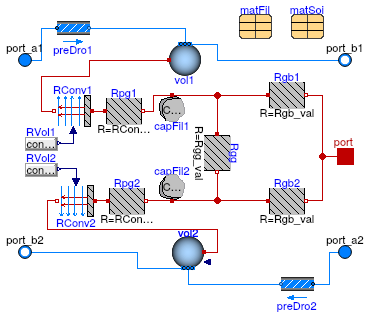
Model for the heat transfer between the fluid and within the borehole filling. This model computes the dynamic response of the fluid in the tubes, the heat transfer between the fluid and the borehole filling, and the heat storage within the fluid and the borehole filling.
This model computes the different thermal resistances present in a single-U-tube borehole using the method of Bauer et al. (2011) and computing explicitly the fluid-to-ground thermal resistance Rb and the grout-to-grout resistance Ra as defined by Hellstroem (1991) using the multipole method. The multipole method is implemented in Buildings.Fluid.Geothermal.Boreholes.BaseClasses.singleUTubeResistances. The convection resistance is calculated using the Dittus-Boelter correlation as implemented in Buildings.Fluid.Geothermal.Boreholes.BaseClasses.convectionResistance.
The figure below shows the thermal network set up by Bauer et al. (2010).
References
G. Hellström. Ground heat storage: thermal analyses of duct storage systems (Theory). Dept. of Mathematical Physics, University of Lund, Sweden, 1991.
D. Bauer, W. Heidemann, H. Müller-Steinhagen, and H.-J. G. Diersch. Thermal resistance and capacity models for borehole heat exchangers . International Journal Of Energy Research, 35:312–320, 2011.
Extends from Buildings.Fluid.Interfaces.FourPortHeatMassExchanger (Model transporting two fluid streams between four ports with storing mass or energy).
Parameters
| Type | Name | Default | Description |
|---|---|---|---|
| replaceable package Medium1 | PartialMedium | Medium 1 in the component | |
| replaceable package Medium2 | PartialMedium | Medium 2 in the component | |
| replaceable package Medium | Modelica.Media.Interfaces.Pa... | Medium in the component | |
| ThermalConductivity | kSoi | Thermal conductivity of the soil used for the calculation of the internal interference resistance [W/(m.K)] | |
| Height | hSeg | Height of the element [m] | |
| Radius | rBor | Radius of the borehole [m] | |
| Length | xC | 0.05 | Shank spacing, defined as half the center-to-center distance between the two pipes [m] |
| Nominal condition | |||
| MassFlowRate | m1_flow_nominal | Nominal mass flow rate [kg/s] | |
| MassFlowRate | m2_flow_nominal | Nominal mass flow rate [kg/s] | |
| PressureDifference | dp1_nominal | Pressure difference [Pa] | |
| PressureDifference | dp2_nominal | Pressure difference [Pa] | |
| Filling material | |||
| Generic | matFil | redeclare parameter Building... | Thermal properties of the filling material |
| Temperature | TFil_start | 283.15 | Initial temperature of the filling material [K] |
| Soil | |||
| Generic | matSoi | redeclare parameter Building... | Thermal properties of soil |
| Pipes | |||
| Radius | rTub | 0.02 | Radius of the tubes [m] |
| ThermalConductivity | kTub | 0.5 | Thermal conductivity of the tubes [W/(m.K)] |
| Length | eTub | 0.002 | Thickness of the tubes [m] |
| Assumptions | |||
| Boolean | allowFlowReversal1 | true | = false to simplify equations, assuming, but not enforcing, no flow reversal for medium 1 |
| Boolean | allowFlowReversal2 | true | = false to simplify equations, assuming, but not enforcing, no flow reversal for medium 2 |
| Advanced | |||
| MassFlowRate | m1_flow_small | 1E-4*abs(m1_flow_nominal) | Small mass flow rate for regularization of zero flow [kg/s] |
| MassFlowRate | m2_flow_small | 1E-4*abs(m2_flow_nominal) | Small mass flow rate for regularization of zero flow [kg/s] |
| Diagnostics | |||
| Boolean | show_T | false | = true, if actual temperature at port is computed |
| Flow resistance | |||
| Medium 1 | |||
| Boolean | from_dp1 | false | = true, use m_flow = f(dp) else dp = f(m_flow) |
| Boolean | linearizeFlowResistance1 | false | = true, use linear relation between m_flow and dp for any flow rate |
| Real | deltaM1 | 0.1 | Fraction of nominal flow rate where flow transitions to laminar |
| Medium 2 | |||
| Boolean | from_dp2 | false | = true, use m_flow = f(dp) else dp = f(m_flow) |
| Boolean | linearizeFlowResistance2 | false | = true, use linear relation between m_flow and dp for any flow rate |
| Real | deltaM2 | 0.1 | Fraction of nominal flow rate where flow transitions to laminar |
| Dynamics | |||
| Nominal condition | |||
| Time | tau1 | Modelica.Constants.pi*rTub^2... | Time constant at nominal flow [s] |
| Time | tau2 | Modelica.Constants.pi*rTub^2... | Time constant at nominal flow [s] |
| Equations | |||
| Dynamics | energyDynamics | Modelica.Fluid.Types.Dynamic... | Type of energy balance: dynamic (3 initialization options) or steady state |
| Dynamics | massDynamics | energyDynamics | Type of mass balance: dynamic (3 initialization options) or steady state |
| Initialization | |||
| Medium 1 | |||
| AbsolutePressure | p1_start | Medium1.p_default | Start value of pressure [Pa] |
| Temperature | T1_start | TFil_start | Start value of temperature [K] |
| MassFraction | X1_start[Medium1.nX] | Medium1.X_default | Start value of mass fractions m_i/m [kg/kg] |
| ExtraProperty | C1_start[Medium1.nC] | fill(0, Medium1.nC) | Start value of trace substances |
| ExtraProperty | C1_nominal[Medium1.nC] | fill(1E-2, Medium1.nC) | Nominal value of trace substances. (Set to typical order of magnitude.) |
| Medium 2 | |||
| AbsolutePressure | p2_start | Medium2.p_default | Start value of pressure [Pa] |
| Temperature | T2_start | TFil_start | Start value of temperature [K] |
| MassFraction | X2_start[Medium2.nX] | Medium2.X_default | Start value of mass fractions m_i/m [kg/kg] |
| ExtraProperty | C2_start[Medium2.nC] | fill(0, Medium2.nC) | Start value of trace substances |
| ExtraProperty | C2_nominal[Medium2.nC] | fill(1E-2, Medium2.nC) | Nominal value of trace substances. (Set to typical order of magnitude.) |
Connectors
| Type | Name | Description |
|---|---|---|
| replaceable package Medium1 | Medium 1 in the component | |
| replaceable package Medium2 | Medium 2 in the component | |
| FluidPort_a | port_a1 | Fluid connector a1 (positive design flow direction is from port_a1 to port_b1) |
| FluidPort_b | port_b1 | Fluid connector b1 (positive design flow direction is from port_a1 to port_b1) |
| FluidPort_a | port_a2 | Fluid connector a2 (positive design flow direction is from port_a2 to port_b2) |
| FluidPort_b | port_b2 | Fluid connector b2 (positive design flow direction is from port_a2 to port_b2) |
| replaceable package Medium | Medium in the component | |
| HeatPort_a | port | Heat port that connects to filling material |
Modelica definition
 Buildings.Fluid.Geothermal.Boreholes.BaseClasses.SingleUTubeBoundaryCondition
Prescribed temperature at the outer boundary of a single U tube borehole

Information
This model computes the temperature boundary condition at the outer boundary of the borehole. It takes as an input the heat flow rate at the center of the borehole. This heat flow rate is averaged over the sample period. At each sampling interval, typically every one week, a new temperature boundary conditions is computed using the analytical solution to a line source heat transfer problem.
Implementation
The computation of the temperature change of the boundary is computed using the function Buildings.Fluid.Geothermal.Boreholes.BaseClasses.temperatureDrop.
Parameters
| Type | Name | Default | Description |
|---|---|---|---|
| Generic | matSoi | redeclare parameter Building... | Thermal properties of the soil |
| Radius | rExt | 3 | Distance from the brine where the calculation is performed [m] |
| Height | hSeg | 10 | Height of the segment [m] |
| Temperature | TExt_start | 283.15 | Initial external temperature [K] |
| Time | samplePeriod | 604800 | Period between two samples [s] |
Connectors
| Type | Name | Description |
|---|---|---|
| input RealInput | Q_flow | Heat flow rate at the center of the borehole, positive if heat is added to soil [W] |
| HeatPort_b | port | Heat port |
Modelica definition
Buildings.Fluid.Geothermal.Boreholes.BaseClasses.convectionResistance
Thermal resistance between the fluid and the tube
Information
This model computes the convection resistance in the pipes of a borehole segment with heigth hSeg.
The correlation of Dittus-Boelter (1930) is used to find the convection heat transfer coefficient as
Nu = 0.023 Re0.8 Prn,
where Nu is the Nusselt number, Re is the Reynolds number and Pr is the Prandlt number. We selected n=0.35, as the reference uses n=0.4 for heating and n=0.3 for cooling. Dittus-Boelter's correlation is valid for turbulent flow in cylindrical smooth pipe.
+References
Dittus P.W. and L.M.K Boelter, (1930). Heat transfer in automobile radiators of the tubular type. Univ Calif Pub Eng, 2(13):443-461. (Reprinted in Int. J. Comm. Heat Mass Transf. 12 (1985), 3:22). DOI:10.1016/0735-1933(85)90003-X.
Inputs
| Type | Name | Default | Description |
|---|---|---|---|
| Height | hSeg | Height of the element [m] | |
| Radius | rTub | Tube radius [m] | |
| ThermalConductivity | kMed | Thermal conductivity of the fluid [W/(m.K)] | |
| DynamicViscosity | mueMed | Dynamic viscosity of the fluid [Pa.s] | |
| SpecificHeatCapacity | cpMed | Specific heat capacity of the fluid [J/(kg.K)] | |
| MassFlowRate | m_flow | Mass flow rate [kg/s] | |
| MassFlowRate | m_flow_nominal | Nominal mass flow rate [kg/s] |
Outputs
| Type | Name | Description |
|---|---|---|
| ThermalResistance | R | Thermal resistance between the fluid and the tube [K/W] |
Modelica definition
Buildings.Fluid.Geothermal.Boreholes.BaseClasses.exchangeValues
Store the value u at the element n in the external object, and return the value of the element i
Information
External function that stores the input value x as the element
a[iX] in the array
a = [a[1], a[2], ...],
and that returns the element a[iY].
The size of the array a is automatically enlarged as needed.
Inputs
| Type | Name | Default | Description |
|---|---|---|---|
| ExtendableArray | table | External object | |
| Integer | iX | One-based index where u needs to be stored in the array of the external object | |
| Real | x | Value to store in the external object | |
| Integer | iY | One-based index of the element that needs to be returned from C to Modelica |
Outputs
| Type | Name | Description |
|---|---|---|
| Real | y | Value of the i-th element |
Modelica definition
Buildings.Fluid.Geothermal.Boreholes.BaseClasses.powerSeries
Power series used to compute far-field temperature
Information
This function computes the power series that is used to compute the far-field temperature.
Inputs
| Type | Name | Default | Description |
|---|---|---|---|
| Real | u | u | |
| Integer | N | Number of coefficients |
Outputs
| Type | Name | Description |
|---|---|---|
| Real | W | Power series |
Modelica definition
Buildings.Fluid.Geothermal.Boreholes.BaseClasses.singleUTubeResistances
Thermal resistances for single U-tube
Information
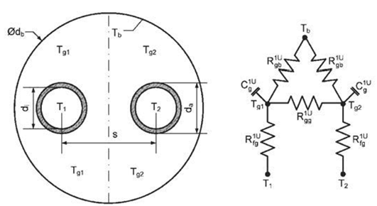
This model computes the thermal resistances of a single-U-tube borehole using the method of Bauer et al. (2011). It also computes the fluid-to-ground thermal resistance Rb and the grout-to-grout thermal resistance Ra as defined by Hellstroem (1991) using the multipole method.
The figure below shows the thermal network set up by Bauer et al. (2011).
The different resistances are calculated as follows. The grout zone and bore hole wall thermal resistance are related as
Rgb1U = ( 1 - x1U ) Rg1U.
The thermal resistance between the two grout zones are
Rgg1U = 2 Rgb1U ( Rar1U - 2 x1U Rg1U ) / ( 2 Rgb1U - Rar1U + 2 x1U Rg1U ).
Thermal resistance between the pipe wall to the capacity in the grout is
RCondGro = x1U Rg1U + log ( ( rTub + eTub ) /rTub ) / ( 2 π hSeg kTub ).
The capacities are located at
x1U =log ( (rBor2 + 2 ( rTub + eTub ) 2)1⁄2/ ( 2 ( rTub + eTub ) ) ) / log ( rBor/ ( √2 ( rTub + eTub ))).
The thermal resistance between the outer borehole wall and one tube is
Rg1U =2 Rb ⁄ hSeg.
The thermal resistance between the two pipe outer walls is
Rar1U =Ra ⁄ hSeg.
The fluid to ground thermal resistance Rb and the grout to grout thermal resistance Ra are calculated with the multipole method (Hellstroem (1991)) as
Rb =1/ ( 4 π kFil ) ( log ( rBor/ ( rTub + eTub ) ) + log ( rBor/ ( 2 xC ) ) + σ log ( rBor4/ ( rBor4 - xC4 ) ) ) - 1/ ( 4 π kFil ) ( ( rTub + eTub ) 2/ ( 4 xC2 ) ( 1 - σ 4 xC4/ ( rBor4 - xC4 ) ) 2 ) / ( ( 1 + β ) / ( 1 - β ) + ( rTub + eTub ) 2/ ( 4 xC2 ) ( 1 + σ 16 xC4 rBor4/ ( rBor4 - xC4 ) 2)).
Ra = 1/ ( π kFil ) ( log ( 2 xC/rTub ) + σ log (( rBor2 + xC2 ) / ( rBor2 - xC2 ) ) ) - 1/ ( π kFil ) ( rTub2/ ( 4 xC2 ) ( 1 + σ 4 rBor4 xC2/ ( rBor4 - xC4 ) ) / ( ( 1 + β ) / ( 1 - β ) - rTub2/ ( 4 xC2 ) + σ 2 rTub2 rBor2 ( rBor4 + xC4 ) / ( rBor4 - xC4 ) 2)),
with σ = ( kFil - kSoi ) / ( kFil + kSoi ) and β = 2 π kFil RCondPipe, where kFil and kSoi are the conductivity of the filling material and of the ground, rTub+eTub and rBor are the pipe and the borehole outside radius and xC is the shank spacing, which is equal to the distance between the center of borehole and the center of the pipe.
Note: The value of Rgg1U may be negative as long as
1/Rgg1U + 1/(2 Rgb1U) > 0,
in which case the laws of thermodynamics are not violated. See Bauer et al. (2011) for details.
References
G. Hellström. Ground heat storage: thermal analyses of duct storage systems (Theory). Dept. of Mathematical Physics, University of Lund, Sweden, 1991.
D. Bauer, W. Heidemann, H. Müller-Steinhagen, and H.-J. G. Diersch. Thermal resistance and capacity models for borehole heat exchangers . International Journal Of Energy Research, 35:312–320, 2011.
Inputs
| Type | Name | Default | Description |
|---|---|---|---|
| Height | hSeg | Height of the element [m] | |
| Radius | rBor | Radius of the borehole [m] | |
| Radius | rTub | Radius of the tube [m] | |
| Length | eTub | Thickness of the tubes [m] | |
| Length | xC | Shank spacing, defined as the distance between the center of a pipe and the center of the borehole [m] | |
| ThermalConductivity | kSoi | Thermal conductivity of the soi [W/(m.K)] | |
| ThermalConductivity | kFil | Thermal conductivity of the grout [W/(m.K)] | |
| ThermalConductivity | kTub | Thermal conductivity of the tube [W/(m.K)] |
Outputs
| Type | Name | Description |
|---|---|---|
| ThermalResistance | Rgb | Thermal resistance between the grout zone and the borehole wall [K/W] |
| ThermalResistance | Rgg | Thermal resistance between the two grout zones [K/W] |
| ThermalResistance | RCondGro | Thermal resistance between the pipe wall ant the capacity in the grout [K/W] |
| Real | x | Capacity location |
Modelica definition
Buildings.Fluid.Geothermal.Boreholes.BaseClasses.temperatureDrop
Calculate the temperature drop of the soil at the external boundary of the cylinder
Information
This function calculates the temperature drop of the soil at the outer boundary of the cylinder. The analytical formula of Hart and Couvillion (1986) for constant heat extraction is adapted to a non-constant heat flux. To adapt the formula for a variable rate of heat extraction, different constant heat extraction rates, starting at different time instances, are super-imposed. To obtain the temperature drop at the time t=n*Δt, the effects of constant rate of heat extractions are super-imposed as
ΔT ( r , t=n Δt )= 1 ⁄ ( 4 π k ) ∑ W(u(r, t= i Δt)) (qn-i+1-qn-i),
where r is the radius for which the temperature is computed, k is the thermal conductivity of the material, W is a solution of the heat conduction in polar coordinates and qi=Qi/h is the specific rate of heat extraction per unit length at time t=i Δt. The value of W is obtained using
W(u)=[-0.5772 - ln(u) + u - u2/(2 2!) +u3/(3 3!) - u4/(4 4!) + ....].
where u(r,t)= c ρ r2 ⁄ (4 t k) , ρ is the mass density and c is the specific heat capacity per unit mass.
Implementation
The rate of heat flow Qi is obtained from the function Buildings.Fluid.Geothermal.Boreholes.BaseClasses.exchangeValues.
References
Hart and Couvillion, (1986). Earth Coupled Heat Transfer. Publication of the National Water Well Association.
Inputs
| Type | Name | Default | Description |
|---|---|---|---|
| ExtendableArray | table | External object that contains the history terms of the heat flux | |
| Integer | iSam | Counter for how many time the model was sampled. Defined as iSam=1 when called at t=0 | |
| HeatFlowRate | Q_flow | Heat flow rate to be stored in the external object [W] | |
| Time | samplePeriod | Period between two samples [s] | |
| Radius | rExt | External radius of the cylinder [m] | |
| Height | hSeg | Height of the cylinder [m] | |
| ThermalConductivity | k | Thermal conductivity of the soil [W/(m.K)] | |
| Density | d | Density of the soil [kg/m3] | |
| SpecificHeatCapacity | c | Specific heat capacity of the soil [J/(kg.K)] |
Outputs
| Type | Name | Description |
|---|---|---|
| TemperatureDifference | dT | Temperature drop of the soil [K] |