Package with controller models
Information
Extends from Modelica.Icons.VariantsPackage (Icon for package containing variants).
Package Content
| Name |
Description |
 ControlBus ControlBus
|
Empty control bus that is adapted to the signals connected to it |
 DuctStaticPressureSetpoint DuctStaticPressureSetpoint
|
Computes the duct static pressure setpoint |
 Economizer Economizer
|
Controller for economizer |
 FanVFD FanVFD
|
Controller for fan revolution |
 ModeSelector ModeSelector
|
Finite State Machine for the operational modes |
 OperationModes OperationModes
|
Enumeration for modes of operation |
 PreCoolingStarter PreCoolingStarter
|
Outputs true when precooling should start |
 RoomTemperatureSetpoint RoomTemperatureSetpoint
|
Set point scheduler for room temperature |
 RoomVAV RoomVAV
|
Controller for room VAV box |
 State State
|
Block that outputs the mode if the state is active, or zero otherwise |
 SupplyAirTemperature SupplyAirTemperature
|
Control block for tracking the supply air temperature set point |
 SupplyAirTemperatureSetpoint SupplyAirTemperatureSetpoint
|
Block computing the supply air temperature set point based on the operation mode |
 Examples Examples
|
Example models to test the components |
Types and constants
type OperationModes = enumeration(
occupied ,
unoccupiedOff ,
unoccupiedNightSetBack ,
unoccupiedWarmUp ,
unoccupiedPreCool ,
safety ) ;
Empty control bus that is adapted to the signals connected to it

Information
This connector defines the expandable connector ControlBus that
is used to connect control signals.
Note, this connector is empty. When using it, the actual content is
constructed by the signals connected to this bus.
Extends from Modelica.Icons.SignalBus (Icon for signal bus).
Modelica definition
Computes the duct static pressure setpoint
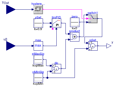
Information
Extends from Modelica.Blocks.Interfaces.MISO (Multiple Input Single Output continuous control block).
Parameters
| Type | Name | Default | Description |
|---|
| Integer | nin | 1 | Number of inputs |
| AbsolutePressure | pMin | 100 | Minimum duct static pressure setpoint [Pa] |
| AbsolutePressure | pMax | 410 | Maximum duct static pressure setpoint [Pa] |
| Real | k | 0.1 | Gain of controller |
| Time | Ti | 60 | Time constant of integrator block [s] |
| Time | Td | 60 | Time constant of derivative block [s] |
| SimpleController | controllerType | Modelica.Blocks.Types.Simple... | Type of controller |
Connectors
| Type | Name | Description |
|---|
| input RealInput | u[nin] | Connector of Real input signals |
| output RealOutput | y | Connector of Real output signal |
| input RealInput | TOut | Outside air temperature |
Modelica definition
model DuctStaticPressureSetpoint
extends Modelica.Blocks.Interfaces.MISO;
parameter Modelica.SIunits.AbsolutePressure pMin(displayUnit="Pa") = 100
;
parameter Modelica.SIunits.AbsolutePressure pMax(displayUnit="Pa") = 410
;
parameter Real k=0.1 ;
parameter Modelica.SIunits.Time Ti=60 ;
parameter Modelica.SIunits.Time Td=60 ;
parameter Modelica.Blocks.Types.SimpleController controllerType=Modelica.Blocks.Types.SimpleController.PI
;
Buildings.Controls.Continuous.LimPID limPID(
controllerType=controllerType,
k=k,
Ti=Ti,
Td=Td,
initType=Modelica.Blocks.Types.InitPID.InitialState,
reverseActing=false);
protected
Buildings.Utilities.Math.Max max(
final nin=nin);
Modelica.Blocks.Sources.Constant ySet(k=0.9)
;
Modelica.Blocks.Math.Add dp(
final k2=-1) ;
Modelica.Blocks.Sources.Constant pMaxSig(k=pMax);
Modelica.Blocks.Sources.Constant pMinSig(k=pMin);
Modelica.Blocks.Math.Add pSet ;
Modelica.Blocks.Math.Product product;
public
Modelica.Blocks.Logical.Hysteresis hysteresis(uLow=283.15, uHigh=284.15)
;
Modelica.Blocks.Interfaces.RealInput TOut ;
protected
Modelica.Blocks.Sources.Constant zero(k=0) ;
public
Modelica.Blocks.Logical.Switch switch1;
equation
connect(max.u, u);
connect(ySet.y, limPID.u_s);
connect(max.y, limPID.u_m);
connect(limPID.y, product.u1);
connect(pMaxSig.y, dp.u1);
connect(pMinSig.y, dp.u2);
connect(dp.y, product.u2);
connect(pMinSig.y, pSet.u2);
connect(pSet.y, y);
connect(hysteresis.u, TOut);
connect(product.y, switch1.u1);
connect(zero.y, switch1.u3);
connect(switch1.y, pSet.u1);
connect(hysteresis.y, switch1.u2);
end DuctStaticPressureSetpoint;
Controller for economizer
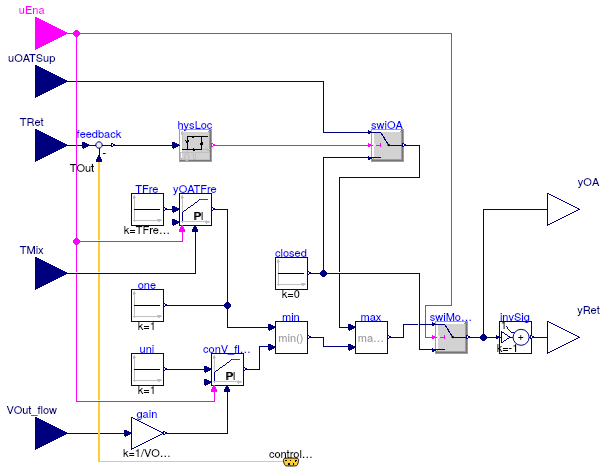
Information
This is a controller for an economizer, that adjusts the mixed air dampers
to fulfill three control functions.
-
Freeze protection, based on the mixed air temperature measurement
-
Minimum outside air requirement, based on the outdoor air flow rate
measurement
-
Supply air cooling, based on the logic implemented in
Buildings.Examples.VAVReheat.Controls.SupplyAirTemperature,
with the additional condition that when the outside air dry bulb is greater
than the return air dry bulb, economizer cooling is disabled.
Parameters
| Type | Name | Default | Description |
|---|
| Boolean | have_reset | false | Set to true to reset the outdoor air damper controllers with the enable signal |
| Boolean | have_frePro | false | Set to true to enable freeze protection (mixed air low temperature control) |
| Temperature | TFreSet | 277.15 | Lower limit of mixed air temperature for freeze protection [K] |
| TemperatureDifference | dTLock | 1 | Temperature difference between return and outdoor air for economizer lockout [K] |
| VolumeFlowRate | VOut_flow_min | | Minimum outside air volume flow rate [m3/s] |
| SimpleController | controllerType | Modelica.Blocks.Types.Simple... | Type of controller |
| Real | k | 0.05 | Gain of controller |
| Time | Ti | 120 | Time constant of integrator block [s] |
Connectors
| Type | Name | Description |
|---|
| input BooleanInput | uEna | Enable signal for economizer |
| ControlBus | controlBus | Control bus |
| input RealInput | uOATSup | Control signal for outdoor air damper from supply temperature controller |
| input RealInput | TMix | Measured mixed air temperature |
| input RealInput | VOut_flow | Measured outside air flow rate |
| input RealInput | TRet | Return air temperature |
| output RealOutput | yRet | Control signal for return air damper |
| output RealOutput | yOA | Control signal for outside air damper |
Modelica definition
block Economizer
import Buildings.Examples.VAVReheat.Controls.OperationModes;
parameter Boolean have_reset = false
;
parameter Boolean have_frePro = false
;
parameter Modelica.SIunits.Temperature TFreSet=277.15
;
parameter Modelica.SIunits.TemperatureDifference dTLock(
final min=0.1) = 1
;
parameter Modelica.SIunits.VolumeFlowRate VOut_flow_min(min=0)
;
parameter Modelica.Blocks.Types.SimpleController controllerType=Modelica.Blocks.Types.SimpleController.PI
;
parameter Real k = 0.05 ;
parameter Modelica.SIunits.Time Ti = 120 ;
Buildings.Controls.OBC.CDL.Interfaces.BooleanInput uEna
;
ControlBus controlBus ;
Modelica.Blocks.Interfaces.RealInput uOATSup
;
Modelica.Blocks.Interfaces.RealInput TMix
if have_frePro
;
Modelica.Blocks.Interfaces.RealInput VOut_flow
;
Modelica.Blocks.Interfaces.RealInput TRet ;
Modelica.Blocks.Interfaces.RealOutput yRet
;
Modelica.Blocks.Interfaces.RealOutput yOA
;
Modelica.Blocks.Math.Gain gain(k=1/VOut_flow_min) ;
Buildings.Controls.Continuous.LimPID conV_flow(
controllerType=controllerType,
k=k,
Ti=Ti,
yMax=1,
yMin=0,
Td=60,
y_reset=0,
final reset=
if have_reset
then Buildings.Types.Reset.Parameter
else
Buildings.Types.Reset.Disabled)
;
Modelica.Blocks.Sources.Constant uni(k=1) ;
Modelica.Blocks.Sources.Constant closed(k=0) ;
Modelica.Blocks.Math.Max max
;
Buildings.Controls.Continuous.LimPID yOATFre(
controllerType=controllerType,
k=k,
Ti=Ti,
Td=60,
yMax=1,
yMin=0,
y_reset=1,
reverseActing=false,
final reset=
if have_reset
then Buildings.Types.Reset.Parameter
else
Buildings.Types.Reset.Disabled)
if have_frePro
;
Modelica.Blocks.Math.Min min
;
Modelica.Blocks.Sources.Constant TFre(k=TFreSet)
;
Buildings.Controls.OBC.CDL.Continuous.AddParameter invSig(p=1, k=-1)
;
Modelica.Blocks.Logical.Hysteresis hysLoc(
final uLow=0,
final uHigh=dTLock)
;
Modelica.Blocks.Math.Feedback feedback;
Buildings.Controls.OBC.CDL.Logical.Switch swiOA
;
Modelica.Blocks.Sources.Constant one(k=1)
if not have_frePro
;
Buildings.Controls.OBC.CDL.Logical.Switch swiModClo
;
equation
connect(VOut_flow, gain.u);
connect(gain.y, conV_flow.u_m);
connect(uni.y, conV_flow.u_s);
connect(min.u2, conV_flow.y);
connect(min.y, max.u2);
connect(yOATFre.y, min.u1);
connect(yRet, invSig.y);
connect(feedback.y, hysLoc.u);
connect(TRet, feedback.u1);
connect(controlBus.TOut, feedback.u2);
connect(swiOA.y, max.u1);
connect(closed.y, swiOA.u3);
connect(hysLoc.y, swiOA.u2);
connect(uOATSup, swiOA.u1);
connect(uEna, yOATFre.trigger);
connect(uEna, conV_flow.trigger);
connect(one.y, min.u1);
connect(yOATFre.u_s, TFre.y);
connect(TMix, yOATFre.u_m);
connect(swiModClo.y, invSig.u);
connect(swiModClo.y, yOA);
connect(uEna, swiModClo.u2);
connect(max.y, swiModClo.u1);
connect(closed.y, swiModClo.u3);
end Economizer;
Controller for fan revolution
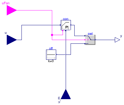
Information
Extends from Modelica.Blocks.Interfaces.SISO (Single Input Single Output continuous control block).
Parameters
| Type | Name | Default | Description |
|---|
| Real | xSet_nominal | | Nominal setpoint (used for normalization) |
| Real | r_N_min | 0.01 | Minimum normalized fan speed |
| Init | initType | Modelica.Blocks.Types.Init.N... | Type of initialization (1: no init, 2: steady state, 3/4: initial output) |
| Real | y_start | 0 | Initial or guess value of output (= state) |
| Setpoint tracking |
| SimpleController | controllerType | Modelica.Blocks.Types.Simple... | Type of controller |
| Real | k | 0.5 | Gain of controller |
| Time | Ti | 15 | Time constant of integrator block [s] |
Connectors
| Type | Name | Description |
|---|
| input RealInput | u | Connector of Real input signal |
| output RealOutput | y | Connector of Real output signal |
| input RealInput | u_m | Connector of measurement input signal |
| input BooleanInput | uFan | Set to true to enable the fan on |
Modelica definition
block FanVFD
extends Modelica.Blocks.Interfaces.SISO;
import Buildings.Examples.VAVReheat.Controls.OperationModes;
Buildings.Controls.OBC.CDL.Continuous.PIDWithReset con(
r=xSet_nominal,
yMax=1,
Td=60,
yMin=r_N_min,
k=k,
Ti=Ti,
controllerType=controllerType)
;
parameter Real xSet_nominal ;
Modelica.Blocks.Sources.Constant off(k=0) ;
Modelica.Blocks.Interfaces.RealInput u_m
;
parameter Real r_N_min=0.01 ;
parameter Modelica.Blocks.Types.Init initType=Modelica.Blocks.Types.Init.NoInit
;
parameter Real y_start=0 ;
parameter Modelica.Blocks.Types.SimpleController
controllerType=Modelica.Blocks.Types.SimpleController.PI
;
parameter Real k=0.5 ;
parameter Modelica.SIunits.Time Ti=15 ;
Buildings.Controls.OBC.CDL.Logical.Switch swi;
Buildings.Controls.OBC.CDL.Interfaces.BooleanInput uFan
;
equation
connect(con.y, swi.u1);
connect(off.y, swi.u3);
connect(swi.u2, uFan);
connect(swi.y, y);
connect(con.trigger, uFan);
connect(con.u_s, u);
connect(u_m, con.u_m);
end FanVFD;
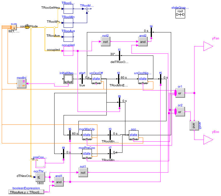
Finite State Machine for the operational modes
Parameters
| Type | Name | Default | Description |
|---|
| TemperatureDifference | delTRooOnOff | 1 | Deadband in room temperature between occupied on and occupied off [K] |
| Temperature | TRooSetHeaOcc | 293.15 | Set point for room air temperature during heating mode [K] |
| Temperature | TRooSetCooOcc | 299.15 | Set point for room air temperature during cooling mode [K] |
Connectors
Modelica definition
model ModeSelector
Modelica.StateGraph.InitialStepWithSignal initialStepWithSignal(nIn=0);
Modelica.StateGraph.Transition start ;
State unOccOff(
mode=Buildings.Examples.VAVReheat.Controls.OperationModes.unoccupiedOff,
nIn=3,
nOut=4) ;
State unOccNigSetBac(
nOut=2,
mode=Buildings.Examples.VAVReheat.Controls.OperationModes.unoccupiedNightSetBack,
nIn=1) ;
Modelica.StateGraph.Transition t2(
enableTimer=true,
waitTime=60,
condition=TRooMinErrHea.y > delTRooOnOff/2);
parameter Modelica.SIunits.TemperatureDifference delTRooOnOff(min=0.1)=1
;
parameter Modelica.SIunits.Temperature TRooSetHeaOcc=293.15
;
parameter Modelica.SIunits.Temperature TRooSetCooOcc=299.15
;
Modelica.StateGraph.Transition t1(condition=delTRooOnOff/2 < -TRooMinErrHea.y,
enableTimer=true,
waitTime=30*60);
inner Modelica.StateGraph.StateGraphRoot stateGraphRoot;
ControlBus cb;
Modelica.Blocks.Routing.RealPassThrough TRooSetHea
;
State morWarUp(mode=Buildings.Examples.VAVReheat.Controls.OperationModes.unoccupiedWarmUp,
nIn=2,
nOut=1) ;
Modelica.StateGraph.TransitionWithSignal t6(enableTimer=true, waitTime=60);
Modelica.Blocks.Logical.LessEqualThreshold occThrSho(threshold=1800)
;
Modelica.StateGraph.TransitionWithSignal t5;
State occ(
mode=Buildings.Examples.VAVReheat.Controls.OperationModes.occupied,
nIn=3)
;
Modelica.Blocks.Routing.RealPassThrough TRooMin;
Modelica.Blocks.Math.Feedback TRooMinErrHea ;
Modelica.StateGraph.Transition t3(condition=TRooMin.y + delTRooOnOff/2 >
TRooSetHeaOcc
or occupied.y);
Modelica.Blocks.Routing.BooleanPassThrough occupied
;
Modelica.StateGraph.TransitionWithSignal t4(enableTimer=false);
State morPreCoo(
nIn=1,
mode=Buildings.Examples.VAVReheat.Controls.OperationModes.unoccupiedPreCool,
nOut=1) ;
Modelica.StateGraph.Transition t7(condition=TRooMin.y - delTRooOnOff/2 <
TRooSetCooOcc
or occupied.y);
Modelica.Blocks.Logical.And and1;
Modelica.Blocks.Routing.RealPassThrough TRooAve ;
Modelica.Blocks.Sources.BooleanExpression booleanExpression(
y=TRooAve.y < TRooSetHeaOcc);
PreCoolingStarter preCooSta(TRooSetCooOcc=TRooSetCooOcc)
;
Modelica.StateGraph.TransitionWithSignal t9;
Modelica.Blocks.Logical.Not not1;
Modelica.Blocks.Logical.And and2;
Modelica.Blocks.Logical.Not not2;
Modelica.StateGraph.TransitionWithSignal t8
;
Modelica.Blocks.MathInteger.Sum sum(nu=6);
Modelica.Blocks.Interfaces.BooleanOutput yFan
;
Modelica.Blocks.MathBoolean.Or or1(nu=4);
Modelica.Blocks.Interfaces.BooleanOutput yEco
;
Modelica.Blocks.MathBoolean.Or or2(nu=2) ;
Buildings.Controls.OBC.CDL.Logical.And and3
;
Modelica.Blocks.Math.BooleanToInteger modIni(integerTrue=
Integer(Buildings.Examples.VAVReheat.Controls.OperationModes.unoccupiedOff))
;
equation
connect(start.outPort, unOccOff.inPort[1]);
connect(initialStepWithSignal.outPort[1], start.inPort);
connect(unOccOff.outPort[1], t2.inPort);
connect(t2.outPort, unOccNigSetBac.inPort[1]);
connect(unOccNigSetBac.outPort[1], t1.inPort);
connect(t1.outPort, unOccOff.inPort[2]);
connect(cb.dTNexOcc, occThrSho.u);
connect(t6.outPort, morWarUp.inPort[1]);
connect(t5.outPort, morWarUp.inPort[2]);
connect(unOccNigSetBac.outPort[2], t5.inPort);
connect(cb.TRooMin, TRooMin.u);
connect(TRooSetHea.y, TRooMinErrHea.u1);
connect(TRooMin.y, TRooMinErrHea.u2);
connect(unOccOff.outPort[2], t6.inPort);
connect(morWarUp.outPort[1], t3.inPort);
connect(cb.occupied, occupied.u);
connect(occ.outPort[1], t4.inPort);
connect(t4.outPort, unOccOff.inPort[3]);
connect(occThrSho.y, and1.u1);
connect(and1.y, t6.condition);
connect(and1.y, t5.condition);
connect(cb.TRooAve, TRooAve.u);
connect(booleanExpression.y, and1.u2);
connect(preCooSta.y, t9.condition);
connect(t9.outPort, morPreCoo.inPort[1]);
connect(unOccOff.outPort[3], t9.inPort);
connect(cb, preCooSta.controlBus);
connect(morPreCoo.outPort[1], t7.inPort);
connect(t7.outPort, occ.inPort[2]);
connect(t3.outPort, occ.inPort[1]);
connect(occThrSho.y, not1.u);
connect(not1.y, and2.u2);
connect(and2.y, t4.condition);
connect(occupied.y, not2.u);
connect(not2.y, and2.u1);
connect(cb.TRooSetHea, TRooSetHea.u);
connect(t8.outPort, occ.inPort[3]);
connect(unOccOff.outPort[4], t8.inPort);
connect(occupied.y, t8.condition);
connect(morPreCoo.y, sum.u[1]);
connect(morWarUp.y, sum.u[2]);
connect(occ.y, sum.u[3]);
connect(unOccOff.y, sum.u[4]);
connect(unOccNigSetBac.y, sum.u[5]);
connect(yFan, or1.y);
connect(unOccNigSetBac.active, or1.u[1]);
connect(occ.active, or1.u[2]);
connect(morWarUp.active, or1.u[3]);
connect(morPreCoo.active, or1.u[4]);
connect(yEco, and3.y);
connect(or1.y, and3.u1);
connect(or2.y, and3.u2);
connect(occ.active, or2.u[1]);
connect(morPreCoo.active, or2.u[2]);
connect(initialStepWithSignal.active, modIni.u);
connect(sum.y, cb.controlMode);
connect(modIni.y, sum.u[6]);
end ModeSelector;
Enumeration for modes of operation
Modelica definition
type OperationModes = enumeration(
occupied ,
unoccupiedOff ,
unoccupiedNightSetBack ,
unoccupiedWarmUp ,
unoccupiedPreCool ,
safety ) ;
Outputs true when precooling should start
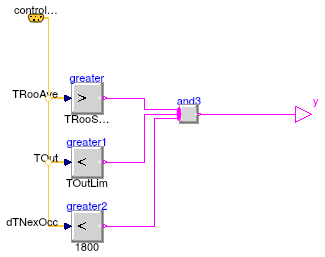
Information
Extends from Modelica.Blocks.Interfaces.BooleanSignalSource (Base class for Boolean signal sources).
Parameters
| Type | Name | Default | Description |
|---|
| Temperature | TOutLim | 286.15 | Limit for activating precooling [K] |
| Temperature | TRooSetCooOcc | | Set point for room air temperature during cooling mode [K] |
Connectors
Modelica definition
Set point scheduler for room temperature
Information
Extends from Modelica.Blocks.Icons.Block (Basic graphical layout of input/output block).
Parameters
| Type | Name | Default | Description |
|---|
| Temperature | THeaOn | 293.15 | Heating setpoint during on [K] |
| Temperature | THeaOff | 285.15 | Heating setpoint during off [K] |
| Temperature | TCooOn | 297.15 | Cooling setpoint during on [K] |
| Temperature | TCooOff | 303.15 | Cooling setpoint during off [K] |
Connectors
Modelica definition
Controller for room VAV box
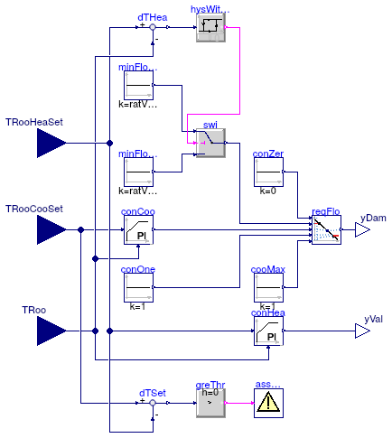
Information
Controller for terminal VAV box with hot water reheat and pressure independent damper.
It is based on the control logic "dual maximum with constant volume heating" as
described in the Advanced VAV System Design Guide (EDR 2007).
Two separate control loops, the cooling loop and the heating loop, are implemented
to maintain space temperature within a temperature dead band (with a required minimum
width of 0.5 K).
The damper control signal yDam corresponds to the discharge air flow rate
set point, normalized to the nominal value.
The control signal for the reheat coil valve yVal corresponds to the
fractional opening (1 corresponding to the valve fully open).
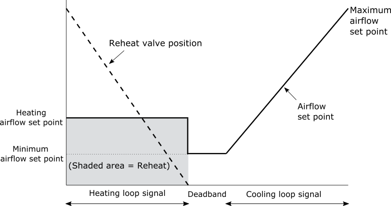
-
Inside the dead band,
yDam is fixed at the minimum value ratVFloMin,
and yVal is 0.
-
In heating demand,
yDam is fixed at the heating value ratVFloHea,
and yVal is modulated between 0 and 1.
-
In cooling demand,
yDam is modulated between the minimum value
ratVFloMin and 1, and yVal is 0.
Note that a single maximum control logic can be represented by simply setting
ratVFloHea equal to ratVFloMin (default setting).
References
EDR (Energy Design Resources).
Advanced Variable Air Volume System Design Guide.
Pacific Gas and Electric Company, 2007.
Extends from Modelica.Blocks.Icons.Block (Basic graphical layout of input/output block).
Parameters
| Type | Name | Default | Description |
|---|
| Real | ratVFloMin | 0.3 | Minimum airflow set point (ratio to nominal) [1] |
| Real | ratVFloHea | ratVFloMin | Heating airflow set point (ratio to nominal) [1] |
| Cooling controller |
| SimpleController | cooController | Buildings.Controls.OBC.CDL.T... | Type of controller |
| Real | kCoo | 0.1 | Gain of controller |
| Time | TiCoo | 120 | Time constant of integrator block [s] |
| Time | TdCoo | 60 | Time constant of derivative block [s] |
| Heating controller |
| SimpleController | heaController | Buildings.Controls.OBC.CDL.T... | Type of controller |
| Real | kHea | 0.1 | Gain of controller |
| Time | TiHea | 120 | Time constant of integrator block [s] |
| Time | TdHea | 60 | Time constant of derivative block [s] |
Connectors
| Type | Name | Description |
|---|
| input RealInput | TRooHeaSet | Setpoint temperature for room for heating [K] |
| input RealInput | TRooCooSet | Setpoint temperature for room for cooling [K] |
| input RealInput | TRoo | Measured room temperature [K] |
| output RealOutput | yDam | Signal for VAV damper |
| output RealOutput | yVal | Signal for heating coil valve |
Modelica definition
block RoomVAV
extends Modelica.Blocks.Icons.Block;
parameter Real ratVFloMin(
final unit="1") = 0.3
;
parameter Real ratVFloHea(
final unit="1") = ratVFloMin
;
parameter Buildings.Controls.OBC.CDL.Types.SimpleController cooController=
Buildings.Controls.OBC.CDL.Types.SimpleController.PI ;
parameter Real kCoo=0.1 ;
parameter Modelica.SIunits.Time TiCoo=120 ;
parameter Modelica.SIunits.Time TdCoo=60 ;
parameter Buildings.Controls.OBC.CDL.Types.SimpleController heaController=
Buildings.Controls.OBC.CDL.Types.SimpleController.PI ;
parameter Real kHea=0.1 ;
parameter Modelica.SIunits.Time TiHea=120 ;
parameter Modelica.SIunits.Time TdHea=60 ;
Buildings.Controls.OBC.CDL.Interfaces.RealInput TRooHeaSet(
final quantity="ThermodynamicTemperature",
final unit = "K",
displayUnit = "degC")
;
Buildings.Controls.OBC.CDL.Interfaces.RealInput TRooCooSet(
final quantity="ThermodynamicTemperature",
final unit = "K",
displayUnit = "degC")
;
Modelica.Blocks.Interfaces.RealInput TRoo(
final quantity="ThermodynamicTemperature",
final unit = "K",
displayUnit = "degC")
;
Modelica.Blocks.Interfaces.RealOutput yDam ;
Modelica.Blocks.Interfaces.RealOutput yVal ;
Buildings.Controls.OBC.CDL.Continuous.PID conHea(
yMax=yMax,
Td=TdHea,
yMin=yMin,
k=kHea,
Ti=TiHea,
controllerType=heaController,
Ni=10) ;
Buildings.Controls.OBC.CDL.Continuous.PID conCoo(
yMax=yMax,
Td=TdCoo,
k=kCoo,
Ti=TiCoo,
controllerType=cooController,
yMin=yMin,
reverseActing=false) ;
Buildings.Controls.OBC.CDL.Continuous.Line reqFlo ;
Buildings.Controls.OBC.CDL.Continuous.Sources.Constant cooMax(k=1)
;
Buildings.Controls.OBC.CDL.Continuous.Sources.Constant minFloCoo(
final k=ratVFloMin)
;
Buildings.Controls.OBC.CDL.Continuous.Sources.Constant conOne(k=1)
;
Buildings.Controls.OBC.CDL.Continuous.Sources.Constant conZer(k=0)
;
Buildings.Controls.OBC.CDL.Continuous.Hysteresis hysWitHol(
final uLow=-dTHys,
final uHigh=0)
;
Buildings.Controls.OBC.CDL.Continuous.Feedback dTHea
;
Buildings.Controls.OBC.CDL.Continuous.Sources.Constant minFloHea(
final k=ratVFloHea)
;
Buildings.Controls.OBC.CDL.Logical.Switch swi
;
Buildings.Controls.OBC.CDL.Utilities.Assert assMes(message=
"The difference between cooling and heating set points must be greater than dTHys")
;
Buildings.Controls.OBC.CDL.Continuous.Feedback dTSet
;
Buildings.Controls.OBC.CDL.Continuous.GreaterThreshold greThr(t=dTHys)
;
protected
parameter Real yMax=1 ;
parameter Real yMin=0 ;
parameter Modelica.SIunits.TemperatureDifference dTHys(
final min=0) = 0.5
;
equation
connect(TRooCooSet, conCoo.u_s);
connect(TRoo, conHea.u_m);
connect(TRooHeaSet, conHea.u_s);
connect(conHea.y, yVal);
connect(conZer.y, reqFlo.x1);
connect(cooMax.y, reqFlo.f2);
connect(conOne.y, reqFlo.x2);
connect(conCoo.y, reqFlo.u);
connect(TRoo, conCoo.u_m);
connect(reqFlo.y, yDam);
connect(TRooHeaSet, dTHea.u1);
connect(dTHea.y, hysWitHol.u);
connect(TRoo, dTHea.u2);
connect(minFloCoo.y, swi.u3);
connect(minFloHea.y, swi.u1);
connect(hysWitHol.y, swi.u2);
connect(swi.y, reqFlo.f1);
connect(TRooCooSet, dTSet.u1);
connect(TRooHeaSet, dTSet.u2);
connect(dTSet.y, greThr.u);
connect(greThr.y, assMes.u);
end RoomVAV;
Block that outputs the mode if the state is active, or zero otherwise
Information
Extends from Modelica.StateGraph.StepWithSignal (Ordinary step (= step that is not active when simulation starts). Connector 'active' is true when the step is active).
Parameters
| Type | Name | Default | Description |
|---|
| Integer | nIn | 1 | Number of input connections |
| Integer | nOut | 1 | Number of output connections |
| OperationModes | mode | | Enter enumeration of mode |
Connectors
Modelica definition
Control block for tracking the supply air temperature set point
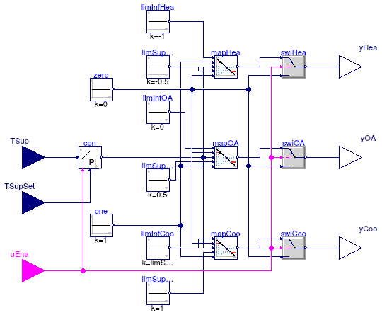
Information
This block implements the control logic for the supply air temperature,
as described in the control sequence VAV 2A2-21232 of the
Sequences of Operation for Common HVAC Systems (ASHRAE, 2006).
The heating coil valve, outdoor air damper, and cooling coil valve are modulated
in sequence to maintain the supply air temperature set point.
A deadband between heating and economizer cooling is also modeled.
Note that the economizer lockout when the outdoor air temperature
is higher than the return air temperature is implemented in
Buildings.Examples.VAVReheat.Controls.Economizer.
References
ASHRAE.
Sequences of Operation for Common HVAC Systems.
ASHRAE, Atlanta, GA, 2006.
Extends from Modelica.Blocks.Icons.Block (Basic graphical layout of input/output block).
Parameters
| Type | Name | Default | Description |
|---|
| Boolean | have_heating | true | Set to true for heating and cooling functions (false for cooling only) |
| SimpleController | controllerType | Buildings.Controls.OBC.CDL.T... | Type of controller |
| Real | k | 0.01 | Gain of controller |
| Time | Ti | 120 | Time constant of integrator block [s] |
| Time | Td | 0.1 | Time constant of derivative block [s] |
Connectors
| Type | Name | Description |
|---|
| input BooleanInput | uEna | Signal enabling set point tracking |
| input RealInput | TSup | Supply air temperature measurement [K] |
| input RealInput | TSupSet | Supply air temperature set point [K] |
| output RealOutput | yHea | Control signal for heating coil valve [1] |
| output RealOutput | yOA | Control signal for outdoor air damper [1] |
| output RealOutput | yCoo | Control signal for cooling coil valve [1] |
Modelica definition
block SupplyAirTemperature
extends Modelica.Blocks.Icons.Block;
parameter Boolean have_heating = true
;
parameter Buildings.Controls.OBC.CDL.Types.SimpleController controllerType=
Buildings.Controls.OBC.CDL.Types.SimpleController.PI ;
parameter Real k(min=0) = 0.01 ;
parameter Modelica.SIunits.Time Ti(
min=Buildings.Controls.OBC.CDL.Constants.small) = 120
;
parameter Modelica.SIunits.Time Td(min=0) = 0.1
;
Buildings.Controls.OBC.CDL.Interfaces.BooleanInput uEna
;
Buildings.Controls.OBC.CDL.Interfaces.RealInput TSup(
final unit="K",
displayUnit="degC")
;
Buildings.Controls.OBC.CDL.Interfaces.RealInput TSupSet(
final unit="K",
displayUnit="degC")
;
Buildings.Controls.OBC.CDL.Interfaces.RealOutput yHea(
final unit="1")
if have_heating
;
Buildings.Controls.OBC.CDL.Interfaces.RealOutput yOA(
final unit="1")
;
Buildings.Controls.OBC.CDL.Interfaces.RealOutput yCoo(
final unit="1")
;
Buildings.Controls.OBC.CDL.Continuous.PIDWithReset con(
final controllerType=controllerType,
final k=k,
final Ti=Ti,
final Td=Td,
final yMax=1,
final yMin=
if have_heating
then -1
else 0,
y_reset=
if have_heating
then limSupHea.k
else limInfOA.k,
u_s(
final unit="K",
displayUnit="degC"),
u_m(
final unit="K",
displayUnit="degC"))
;
Buildings.Controls.OBC.CDL.Continuous.Line mapHea
if have_heating
;
Buildings.Controls.OBC.CDL.Continuous.Line mapOA
;
Buildings.Controls.OBC.CDL.Continuous.Line mapCoo
;
Buildings.Controls.OBC.CDL.Continuous.Sources.Constant limInfHea(k=-1)
;
Buildings.Controls.OBC.CDL.Continuous.Sources.Constant limSupHea(k=-0.5)
;
Buildings.Controls.OBC.CDL.Continuous.Sources.Constant limInfOA(k=0)
;
Buildings.Controls.OBC.CDL.Continuous.Sources.Constant limSupOA(k=0.5)
;
Buildings.Controls.OBC.CDL.Continuous.Sources.Constant limSupCoo(k=1)
;
Buildings.Controls.OBC.CDL.Continuous.Sources.Constant zero(k=0) ;
Buildings.Controls.OBC.CDL.Continuous.Sources.Constant one(k=1) ;
Buildings.Controls.OBC.CDL.Logical.Switch swiHea
if have_heating
;
Buildings.Controls.OBC.CDL.Logical.Switch swiCoo
;
Buildings.Controls.OBC.CDL.Logical.Switch swiOA
;
Buildings.Controls.OBC.CDL.Continuous.Sources.Constant limInfCoo(
k=limSupOA.k)
;
equation
connect(TSup, con.u_s);
connect(TSupSet, con.u_m);
connect(con.y, mapOA.u);
connect(con.y, mapCoo.u);
connect(con.y, mapHea.u);
connect(limInfHea.y, mapHea.x1);
connect(limSupHea.y, mapHea.x2);
connect(limInfOA.y, mapOA.x1);
connect(limSupOA.y, mapOA.x2);
connect(limSupCoo.y, mapCoo.x2);
connect(one.y, mapCoo.f2);
connect(zero.y, mapHea.f2);
connect(one.y, mapOA.f2);
connect(zero.y, mapOA.f1);
connect(one.y, mapHea.f1);
connect(zero.y, mapCoo.f1);
connect(swiHea.y, yHea);
connect(mapHea.y, swiHea.u1);
connect(mapCoo.y, swiCoo.u1);
connect(zero.y, swiHea.u3);
connect(zero.y, swiCoo.u3);
connect(swiOA.y, yOA);
connect(mapOA.y, swiOA.u1);
connect(zero.y, swiOA.u3);
connect(uEna, swiCoo.u2);
connect(uEna, swiOA.u2);
connect(uEna, swiHea.u2);
connect(swiCoo.y, yCoo);
connect(limInfCoo.y, mapCoo.x1);
connect(uEna, con.trigger);
end SupplyAirTemperature;
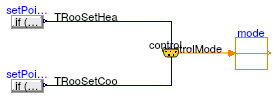
Block computing the supply air temperature set point based on the operation mode
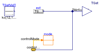
Information
This block computes the supply air temperature set point
based on the actual operating mode.
The default set point values are taken from the control sequence
VAV 2A2-21232 of the Sequences of Operation for
Common HVAC Systems (ASHRAE, 2006).
| Operating mode | Set point value [C] |
| Occupied | 12 |
| Unoccupied off | 12 |
| Unoccupied, night set back | 35 |
| Unoccupied, warm-up | 35 |
| Unoccupied, pre-cool | 12 |
| Safety | 7 |
References
ASHRAE.
Sequences of Operation for Common HVAC Systems.
ASHRAE, Atlanta, GA, 2006.
Extends from Modelica.Blocks.Icons.Block (Basic graphical layout of input/output block).
Connectors
Modelica definition
 Buildings.Examples.VAVReheat.Controls.ControlBus
 Buildings.Examples.VAVReheat.Controls.DuctStaticPressureSetpoint
 Buildings.Examples.VAVReheat.Controls.Economizer
 Buildings.Examples.VAVReheat.Controls.FanVFD
 Buildings.Examples.VAVReheat.Controls.ModeSelector
 Buildings.Examples.VAVReheat.Controls.PreCoolingStarter
 Buildings.Examples.VAVReheat.Controls.RoomTemperatureSetpoint
 Buildings.Examples.VAVReheat.Controls.RoomVAV
 Buildings.Examples.VAVReheat.Controls.State
 Buildings.Examples.VAVReheat.Controls.SupplyAirTemperature
 Buildings.Examples.VAVReheat.Controls.SupplyAirTemperatureSetpoint