Package with example for how to build a model for boiler with a heating load
Information
This package contains examples with step-by-step instructions for how to build
a system model for a boiler with a heat load as shown in the figure below.
The pressure drops of the individual flow branches and the temperatures correspond to design conditions.
The heating system shall be designed to provide 20 kW, which is the load
needed at -10°C outdoor temperature.
This load already takes into account the heat required for air infiltration and
ventilation.
Using this load and the temperatures shown in the schematic drawing,
the nominal mass flow rates of the individual flow branches should be computed.
From 8:00 to 18:00, there is an internal heat gain of 4kW,
which should not be accounted for when sizing the system.
The room volume is 180m3.
To approximate the thermal storage effect of furniture and building constructions,
the heat capacity of the room should be increased by a factor of three.
(Modeling a detailed room heat transfer as implemented in
Buildings.ThermalZones.Detailed is out of scope for this tutorial.)
The space heating shall be switched on if the outdoor temperature is below
16°C and the room temperature is below
20°C.
It shall be switched off if either the outdoor temperature is above
17°C or the room temperature is above
21°C.
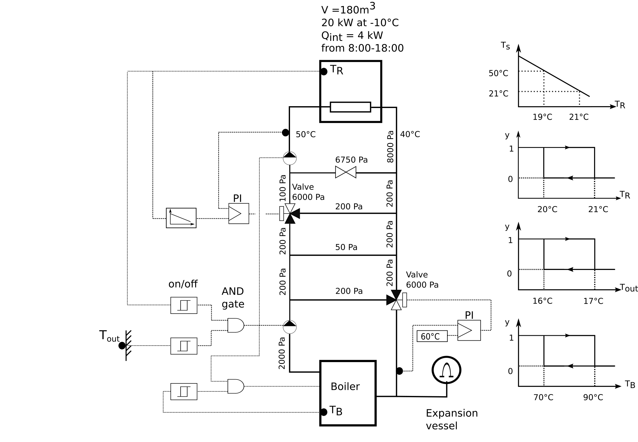
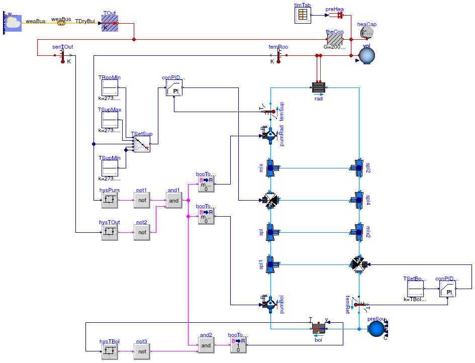
The model consists of
-
a room with a heating load, approximated as steady-state heat transfer with the environment,
-
a heating loop with a constant bypass and a three-way valve, which is modulated to track the room temperature set point, and
-
a boiler loop with constant mass flow rate, boiler on/off control and control valve
to ensure a minimum return water temperature.
To explain the implementation of this model, the model has been created in the following stages:
-
Buildings.Examples.Tutorial.Boiler.System1
implements the room model without any heating.
-
Buildings.Examples.Tutorial.Boiler.System2
adds a radiator that is fed with water at a constant temperature and flow rate.
The pump is switched on and off depending on the room temperature.
-
Buildings.Examples.Tutorial.Boiler.System3
adds the boiler circuit with open loop control for the boiler and the mixing valves.
-
Buildings.Examples.Tutorial.Boiler.System4
adds closed loop control for the boiler and the pumps.
-
Buildings.Examples.Tutorial.Boiler.System5
adds closed loop control for the two valves.
-
Buildings.Examples.Tutorial.Boiler.System6
replaces the constant outdoor temperature with weather data from a file,
and changes the valve control from P-control to PI-control.
-
Buildings.Examples.Tutorial.Boiler.System7
replaces the boiler and pump control using a state machine.
Extends from Modelica.Icons.ExamplesPackage (Icon for packages containing runnable examples).
Package Content
| Name |
Description |
 System1 System1
|
1st part of the system model, consisting of the room with heat transfer |
| System2
|
2nd part of the system model, consisting of the room with heat transfer and a radiator |
| System3
|
3rd part of the system model, which adds the boiler loop with open loop control |
| System4
|
4th part of the system model, which adds closed-loop control for the pumps and the boiler |
| System5
|
5th part of the system model, which adds closed-loop control for the valves |
| System6
|
6th part of the system model, which adds weather data and changes to PI control |
| System7
|
7th part of the system model, which implements the on/off control using a state machine |
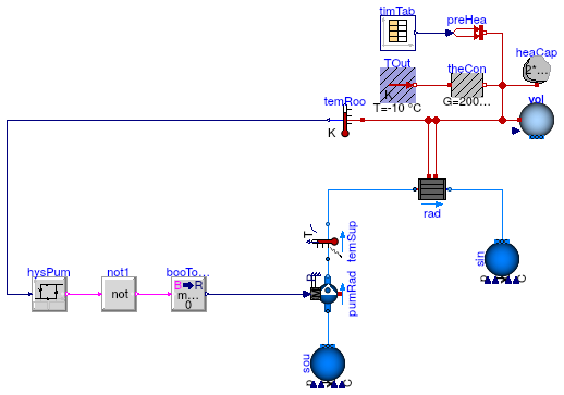
1st part of the system model, consisting of the room with heat transfer
Information
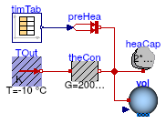
This part of the system model implements the room with a heat gain.
The room is simplified as a volume of air, a prescribed heat source for
the internal convective heat gain, and a heat conductor for steady-state
heat conduction to the outside.
To increase the heat capacity of the room, such as due to heat stored
in furniture and in building constructions, the heat capacity
of the room air was increased by a factor of three.
The convective heat transfer coefficient is lumped into the heat conductor
model.
Implementation
This section describes step by step how we implemented the model.
-
First, to define the medium properties, we added the declaration
  replaceable package MediumA =
      Buildings.Media.Air;
This will allow the propagation of the medium model to all models that contain air.
In this example, there is only one model with air.
We called the medium MediumA to distinguish it from
MediumW that we will use in later versions of the model for components that
have water as a medium.
We also defined the system-level parameters
  parameter Modelica.SIunits.Volume V=6*10*3 "Room volume";
  parameter Modelica.SIunits.MassFlowRate mA_flow_nominal = V*1.2*6/3600
    "Nominal mass flow rate";
  parameter Modelica.SIunits.HeatFlowRate QRooInt_flow = 4000
    "Internal heat gains of the room";
to declare that the room volume is 180 m3, that the room
has a nominal mass flow rate of 6 air changes per hour and that
the internal heat gains of the room are 4000 Watts.
These parameters have been declared at the top-level of the model
as they will be used in several other models.
Declaring them at the top-level allows to propagate them to other
models, and to easily change them at one location should this be required
when revising the model.
-
To model the room air, approximated as a completely mixed volume of air,
an instance of
Buildings.Fluid.MixingVolumes.MixingVolume
has been used, as this model can be used with dry air or moist air.
The medium model has been set to MediumA, and the nominal mass
flow rate is set to mA_flow_nominal.
The nominal mass flow rate is used for numerical reasons and should be set
to the approximate order of magnitude. It only has an effect if the mass flow
rate is near zero and what "near zero" means depends on the magnitude of
m_flow_nominal, as it is used for the default value of the parameter
m_flow_small on the Assumptions tag of the model.
See also
Buildings.Fluid.UsersGuide
for an explanation of the purpose of m_flow_small.
-
Since we need to increase the heat capacity of the room air to approximate
energy storage in furniture and building constructions, we connected the instance heaCap of
Modelica.Thermal.HeatTransfer.Components.HeatCapacitor
to the heat port of the room air.
The model heaCap models energy storage. We set its capacity to
C=2*V*1.2*1006 J/K. This will increase the total heat capacity
of the room air by a factor of three.
-
We used the instance theCon of
Modelica.Thermal.HeatTransfer.Components.ThermalConductor
to model the thermal conductance to the ambient.
Since our room should have a heat loss of 20 kW at a temperature difference
of 30 Kelvin, we set the conductance to
G=20000 ⁄ 30 W/K.
-
We used the instance preHea of
Modelica.Thermal.HeatTransfer.Sources.PrescribedHeatFlow
to model a prescribed heat gain,
such as due to internal heat source.
This model outputs the heat gain which is equal to the value of its
input signal, which is obtained from a time table.
-
To define a time-dependent heat gain, we instantiated the block
Buildings.Controls.OBC.CDL.Continuous.Sources.TimeTable
and set its name to timTab.
We set the table parameters to
  Buildings.Controls.OBC.CDL.Continuous.Sources.TimeTable timTab(
      extrapolation=Buildings.Controls.OBC.CDL.Types.Extrapolation.Periodic,
      smoothness=Buildings.Controls.OBC.CDL.Types.Smoothness.ConstantSegments,
      table=[-6, 0;
              8, QRooInt_flow;
             18, 0],
      timeScale=3600) "Time table for internal heat gain";
Note that we set the output to be a periodic signal by configuring
extrapolation=Buildings.Controls.OBC.CDL.Types.Extrapolation.Periodic.
The first time stamp is -6 hours in order to create
a table that has a periodicity of one day.
We also set the interpolation of the data to using
piece-wise constant segments.
See the documentation of
Buildings.Controls.OBC.CDL.Continuous.Sources.TimeTable for the various options
of this time table.
-
Next, we connected its output to the input of the instance preHea.
This completes the initial version of the model. When simulating the model
for 2 days, or 172800 seconds, the
response shown below should be seen.
To verify the correctness of the model, we can compare the simulated results to the
following analytical solutions:
-
When the internal heat gain is zero, the room temperature should be equal
to the outside temperature.
-
At steady-state when the internal heat gain is 4000 Watts,
the temperature difference to the outside should be
Δ T = Q̇ ⁄ UA = 4000/(20000/30) = 6 Kelvin, which
corresponds to a room temperature of -4°C.
Both analytical values agree with the simulation results shown in the above figure.
An alternative validation can be done by fixing the temperature of the volume to
20°C and plotting the heat flow rate that is needed to maintain
this temperature.
This can be implemented by connecting an instance of
Modelica.Thermal.HeatTransfer.Sources.FixedTemperature
as shown below.
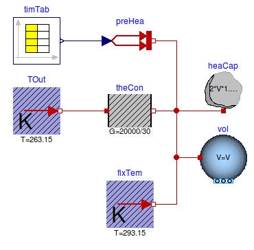
When plotting the heat flow rate fixTemp.port.Q_flow, one can see
that the required heat flow rate to keep the temperature at
20°C is
20 kW during night, and
16 kW during day when the heat gain is active.
Notes
For a more realistic model of a room, the model
Buildings.ThermalZones.Detailed.MixedAir
could have been used.
For transient heat conduction, models from the
package
Buildings.HeatTransfer.Conduction
could have been used.
Extends from Modelica.Icons.Example (Icon for runnable examples).
Parameters
| Type | Name | Default | Description |
|---|
| replaceable package MediumA | Buildings.Media.Air | |
| Volume | V | 6*10*3 | Room volume [m3] |
| MassFlowRate | mA_flow_nominal | V*1.2*6/3600 | Nominal mass flow rate [kg/s] |
| HeatFlowRate | QRooInt_flow | 4000 | Internal heat gains of the room [W] |
Connectors
| Type | Name | Description |
|---|
| replaceable package MediumA | |
Modelica definition
model System1
extends Modelica.Icons.Example;
replaceable package MediumA =
Buildings.Media.Air;
Buildings.Fluid.MixingVolumes.MixingVolume vol(
redeclare package Medium =
MediumA,
energyDynamics=Modelica.Fluid.Types.Dynamics.FixedInitial,
m_flow_nominal=mA_flow_nominal,
V=V);
Modelica.Thermal.HeatTransfer.Components.ThermalConductor theCon(G=20000/30)
;
parameter Modelica.SIunits.Volume V=6*10*3 ;
parameter Modelica.SIunits.MassFlowRate mA_flow_nominal = V*1.2*6/3600
;
parameter Modelica.SIunits.HeatFlowRate QRooInt_flow = 4000
;
Modelica.Thermal.HeatTransfer.Sources.FixedTemperature TOut(T=263.15)
;
Modelica.Thermal.HeatTransfer.Sources.PrescribedHeatFlow preHea
;
Modelica.Thermal.HeatTransfer.Components.HeatCapacitor heaCap(C=2*V*1.2*1006)
;
Buildings.Controls.OBC.CDL.Continuous.Sources.TimeTable timTab(
extrapolation=Buildings.Controls.OBC.CDL.Types.Extrapolation.Periodic,
smoothness=Buildings.Controls.OBC.CDL.Types.Smoothness.ConstantSegments,
table=[-6, 0;
8, QRooInt_flow;
18, 0],
timeScale=3600) ;
equation
connect(TOut.port, theCon.port_a);
connect(theCon.port_b, vol.heatPort);
connect(preHea.port, vol.heatPort);
connect(heaCap.port, vol.heatPort);
connect(timTab.y[1], preHea.Q_flow);
end System1;
2nd part of the system model, consisting of the room with heat transfer and a radiator
Information
This part of the system model adds a radiator with a prescribed mass flow
rate to the system that is implemented in
Buildings.Examples.Tutorial.Boiler.System1.
Implementation
This model was built as follows:
-
First, we copied the model
Buildings.Examples.Tutorial.Boiler.System1
and called it
Buildings.Examples.Tutorial.Boiler.System2.
-
Since this model uses water as the medium, we declared the water medium model
at the top-level of the model by adding the lines
  replaceable package MediumW =
      Buildings.Media.Water "Medium model";
-
To model the pump, a temperature sensor which we will need later
for the control, and a flow sink, we made instances of the models
Buildings.Fluid.Movers.FlowControlled_m_flow
(instance pumRad for the pump that serves the radiators),
Buildings.Fluid.Sensors.TemperatureTwoPort
(instance temSup),
Buildings.Fluid.HeatExchangers.Radiators.RadiatorEN442_2
(instance rad), and
Buildings.Fluid.Sources.Boundary_pT
(instance sou and sin for the sink and source
reservoirs, which will later be replace by the boiler loop).
In all of these instances, we set the medium model to MediumW.
We also made an instance of the model
Modelica.Thermal.HeatTransfer.Sensors.TemperatureSensor
(instance temRoo) to measure the room temperature.
We connected the model as shown in the figure below.
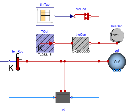
Note that there are two connections from the
radiator to the room volume:
One connection is for the convective heat flow rate, and the other is for the
radiative heat flow rate. For simplicity, we assumed that the air and radiative
temperature of the room are equal.
Furthermore, we simplified the model by using only one radiator instead of multiple
radiators, although this radiator will be quite large as it needs to provide a
heat flow rate of 20 kW.
-
Next, we computed the design mass flow rate for the radiator.
According to the schematic drawing, the radiator should have at
the design conditions a supply water temperature of
50°C and a return water temperature of
40°C.
Thus, we define the radiator mass flow rate as
  parameter Modelica.SIunits.HeatFlowRate Q_flow_nominal = 20000
    "Nominal heat flow rate of radiator";
  parameter Modelica.SIunits.Temperature TRadSup_nominal = 273.15+50
    "Radiator nominal supply water temperature";
  parameter Modelica.SIunits.Temperature TRadRet_nominal = 273.15+40
    "Radiator nominal return water temperature";
  parameter Modelica.SIunits.MassFlowRate mRad_flow_nominal =
    Q_flow_nominal/4200/(TRadSup_nominal-TRadRet_nominal)
    "Radiator nominal mass flow rate";
-
Now, we set the mass flow rate of pumRad and temSup to
mRad_flow_nominal.
We also set the temperature of the fluid that flows out of sou
to TRadSup_nominal.
We configured the parameters of the radiator model as
  Buildings.Fluid.HeatExchangers.Radiators.RadiatorEN442_2 rad(
    redeclare package Medium = MediumW,
    energyDynamics=Modelica.Fluid.Types.Dynamics.FixedInitial,
    Q_flow_nominal=Q_flow_nominal,
    T_a_nominal=TRadSup_nominal,
    T_b_nominal=TRadRet_nominal) "Radiator";
We configured the parameters of the pump model as
  Buildings.Fluid.Movers.FlowControlled_m_flow pumRad(
    redeclare package Medium = MediumW,
    energyDynamics=Modelica.Fluid.Types.Dynamics.FixedInitial,
    m_flow_nominal=mRad_flow_nominal)
    "Pump for radiator";
-
To enable the pump when the room temperature is below
19°C and to switch it off when the room temperature
is below
21°C,
we implemented the control blocks as shown in the figure below.
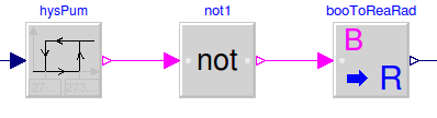
In this control sequence, the first block is a hysteresis element,
which is modeled by
Buildings.Controls.OBC.CDL.Continuous.Hysteresis.
It is configured as
  Buildings.Controls.OBC.CDL.Continuous.Hysteresis hysPum(
    uLow=273.15 + 19,
    uHigh=273.15 + 21)
    "Pump hysteresis";
to output false when the input signal falls below 19°C, and
true when the input signal raises above 21°C.
Next, we send the output to the instance not1, which outputs
y= not u
to negate the signal.
The output of this signal is a boolean value, but the pump
input signal is the required mass flow rate.
Thus, we used the block
Buildings.Controls.OBC.CDL.Conversions.BooleanToReal to convert the signal.
We set the parameters of the boolean to real converter as
  Buildings.Controls.OBC.CDL.Conversions.BooleanToReal booToReaRad(
        realTrue=mRad_flow_nominal,
        realFalse=0) "Radiator pump signal";
For numerical reasons, in particular in large system models, it is recommended to
continuously change the mass flow rate, as opposed to having a step change.
Therefore,
in the instance pumRad, we leave the parameter
use_inputFilter at its default value true.
This will approximate a continuous change in mass flow rate when the
pump is switched on or off.
Finally, we closed the control loop between the room temperature sensor and the
pump input signal.
This completes the initial version of the model. When simulating the model
for 2 days, or 172800 seconds, the
response shown below should be seen.
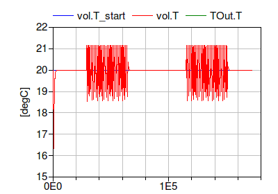
The figure shows that the room temperature is maintained at
20°C when the internal heat gain is zero, and controlled around
19°C to 21°C when there is an internal heat gain.
The temperature is slightly outside this temperature range because of the
time lag that is caused by the thermal capacity of the radiator.
Notes
For a more realistic model of a room, the model
Buildings.ThermalZones.Detailed.MixedAir
could have been used.
For transient heat conduction, models from the
package
Buildings.HeatTransfer.Conduction
could have been used.
Extends from Modelica.Icons.Example (Icon for runnable examples).
Parameters
| Type | Name | Default | Description |
|---|
| replaceable package MediumA | Buildings.Media.Air | |
| replaceable package MediumW | Buildings.Media.Water | Medium model |
| HeatFlowRate | Q_flow_nominal | 20000 | Nominal heat flow rate of radiator [W] |
| Temperature | TRadSup_nominal | 273.15 + 50 | Radiator nominal supply water temperature [K] |
| Temperature | TRadRet_nominal | 273.15 + 40 | Radiator nominal return water temperature [K] |
| MassFlowRate | mRad_flow_nominal | Q_flow_nominal/4200/(TRadSup... | Radiator nominal mass flow rate [kg/s] |
| Volume | V | 6*10*3 | Room volume [m3] |
| MassFlowRate | mA_flow_nominal | V*1.2*6/3600 | Nominal mass flow rate [kg/s] |
| HeatFlowRate | QRooInt_flow | 4000 | Internal heat gains of the room [W] |
Connectors
| Type | Name | Description |
|---|
| replaceable package MediumA | |
| replaceable package MediumW | Medium model |
Modelica definition
model System2
extends Modelica.Icons.Example;
replaceable package MediumA =
Buildings.Media.Air;
replaceable package MediumW =
Buildings.Media.Water ;
parameter Modelica.SIunits.HeatFlowRate Q_flow_nominal = 20000
;
parameter Modelica.SIunits.Temperature TRadSup_nominal = 273.15+50
;
parameter Modelica.SIunits.Temperature TRadRet_nominal = 273.15+40
;
parameter Modelica.SIunits.MassFlowRate mRad_flow_nominal=
Q_flow_nominal/4200/(TRadSup_nominal-TRadRet_nominal)
;
Buildings.Fluid.MixingVolumes.MixingVolume vol(
redeclare package Medium =
MediumA,
energyDynamics=Modelica.Fluid.Types.Dynamics.FixedInitial,
m_flow_nominal=mA_flow_nominal,
V=V);
Modelica.Thermal.HeatTransfer.Components.ThermalConductor theCon(G=20000/30)
;
parameter Modelica.SIunits.Volume V=6*10*3 ;
parameter Modelica.SIunits.MassFlowRate mA_flow_nominal = V*1.2*6/3600
;
parameter Modelica.SIunits.HeatFlowRate QRooInt_flow = 4000
;
Modelica.Thermal.HeatTransfer.Sources.FixedTemperature TOut(T=263.15)
;
Modelica.Thermal.HeatTransfer.Sources.PrescribedHeatFlow preHea
;
Modelica.Thermal.HeatTransfer.Components.HeatCapacitor heaCap(C=2*V*1.2*1006)
;
Buildings.Controls.OBC.CDL.Continuous.Sources.TimeTable timTab(
extrapolation=Buildings.Controls.OBC.CDL.Types.Extrapolation.Periodic,
smoothness=Buildings.Controls.OBC.CDL.Types.Smoothness.ConstantSegments,
table=[-6, 0;
8, QRooInt_flow;
18, 0],
timeScale=3600) ;
Buildings.Fluid.HeatExchangers.Radiators.RadiatorEN442_2 rad(
redeclare package Medium =
MediumW,
energyDynamics=Modelica.Fluid.Types.Dynamics.FixedInitial,
Q_flow_nominal=Q_flow_nominal,
T_a_nominal=TRadSup_nominal,
T_b_nominal=TRadRet_nominal) ;
Buildings.Fluid.Sources.Boundary_pT sin(nPorts=1,
redeclare package Medium =
MediumW)
;
Buildings.Fluid.Sensors.TemperatureTwoPort temSup(
redeclare package Medium =
MediumW,
m_flow_nominal=mRad_flow_nominal) ;
Modelica.Thermal.HeatTransfer.Sensors.TemperatureSensor temRoo
;
Buildings.Fluid.Movers.FlowControlled_m_flow pumRad(
redeclare package Medium =
MediumW,
energyDynamics=Modelica.Fluid.Types.Dynamics.FixedInitial,
m_flow_nominal=mRad_flow_nominal) ;
Buildings.Fluid.Sources.Boundary_pT sou(
nPorts=1,
redeclare package Medium =
MediumW,
T=TRadSup_nominal) ;
Buildings.Controls.OBC.CDL.Continuous.Hysteresis hysPum(
uLow=273.15 + 19,
uHigh=273.15 + 21)
;
Buildings.Controls.OBC.CDL.Conversions.BooleanToReal booToReaRad(realTrue=mRad_flow_nominal)
;
Buildings.Controls.OBC.CDL.Logical.Not not1 ;
equation
connect(TOut.port, theCon.port_a);
connect(theCon.port_b, vol.heatPort);
connect(preHea.port, vol.heatPort);
connect(heaCap.port, vol.heatPort);
connect(timTab.y[1], preHea.Q_flow);
connect(temSup.port_b, rad.port_a);
connect(rad.port_b, sin.ports[1]);
connect(temRoo.port, vol.heatPort);
connect(rad.heatPortCon, vol.heatPort);
connect(rad.heatPortRad, vol.heatPort);
connect(sou.ports[1], pumRad.port_a);
connect(pumRad.port_b, temSup.port_a);
connect(temRoo.T, hysPum.u);
connect(hysPum.y, not1.u);
connect(not1.y, booToReaRad.u);
connect(booToReaRad.y, pumRad.m_flow_in);
end System2;
3rd part of the system model, which adds the boiler loop with open loop control
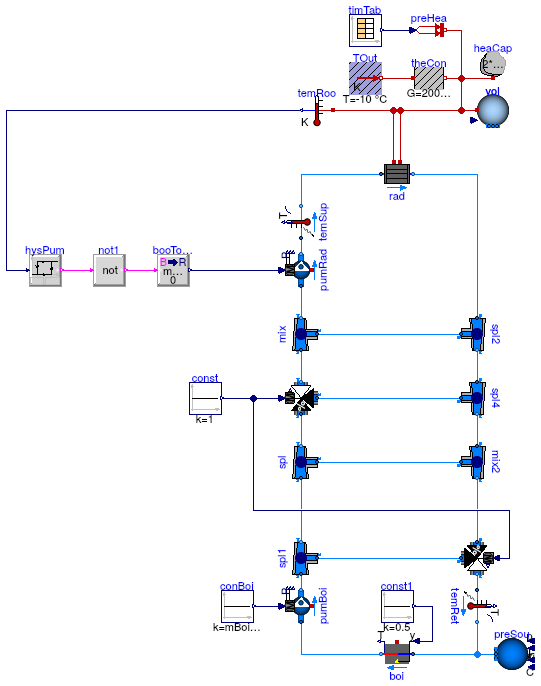
Information
This part of the system model adds the boiler loop with
open loop control to the model that is implemented in
Buildings.Examples.Tutorial.Boiler.System2.
Implementation
This model was built as follows:
-
First, we copied the model
Buildings.Examples.Tutorial.Boiler.System2
and called it
Buildings.Examples.Tutorial.Boiler.System3.
-
Next, we deleted the sink and source models sin and sou,
as these will be replaced by the boiler loop.
-
We made various instances of
Buildings.Fluid.FixedResistances.Junction
to model flow splitter and mixers.
We also made an instance of
Buildings.Fluid.Actuators.Valves.ThreeWayEqualPercentageLinear
to model the three-way valves, and
an instance of
Buildings.Fluid.Boilers.BoilerPolynomial
to model the boiler.
Note that we also made an instance of
Buildings.Fluid.Sources.Boundary_pT,
which we called preSou.
This is required to set a pressure reference in the water loop, which is a closed system.
For medium models that expand with increasing temperature,
this is also required to accumulate, and to feed back into the system,
the difference in mass due to the thermal expansion of water.
-
Next, we parameterized the medium of all these components by
setting it to MediumW.
Since the nominal mass flow rate for the
boiler loop is required by several models, we introduced
the following system-level parameters, where
TBoiRet_min will be used to avoid
condensation in the boiler:
  parameter Modelica.SIunits.Temperature TBoiSup_nominal = 273.15+80
    "Boiler nominal supply water temperature";
  parameter Modelica.SIunits.Temperature TBoiRet_min = 273.15+60
    "Boiler minimum return water temperature";
  parameter Modelica.SIunits.MassFlowRate mBoi_flow_nominal=
    Q_flow_nominal/4200/(TBoiSup_nominal-TBoiRet_min)
    "Boiler nominal mass flow rate";
Next, we set the parameters of the individual component models.
-
We lumped the pressure drop of the boiler loop into the boiler model
and hence set
  Buildings.Fluid.Boilers.BoilerPolynomial boi(
    redeclare package Medium = MediumW,
    energyDynamics=Modelica.Fluid.Types.Dynamics.FixedInitial,
    m_flow_nominal=mBoi_flow_nominal,
    dp_nominal=2000,
    Q_flow_nominal=Q_flow_nominal,
    fue=Buildings.Fluid.Data.Fuels.HeatingOilLowerHeatingValue()) "Boiler";
-
For the three-way valve in the radiator loop, we used the default pressure drop of
6000 Pa.
For its mass flow rate, we introduced the parameter
  parameter Modelica.SIunits.MassFlowRate mRadVal_flow_nominal=
    Q_flow_nominal/4200/(TBoiSup_nominal-TRadRet_nominal)
    "Radiator nominal mass flow rate";
This allowed us to configure the valve as
  Buildings.Fluid.Actuators.Valves.ThreeWayEqualPercentageLinear valRad(
    redeclare package Medium = MediumW,
    m_flow_nominal=mRadVal_flow_nominal,
    l={0.01,0.01},
    dpValve_nominal=6000) "Three-way valve for radiator loop"
where l={0.01,0.01} is a valve leakage of 1%
and dpValve_nominal=6000 is the pressure drop of the valve
if it is fully open
and if the mass flow rate is equal to m_flow_nominal.
It is recommended to set the valve leakage to a non-zero value to avoid numerical problems.
A non-zero value also represent a more realistic situation, as most valves have some leakage.
-
For the bypass between the valve and the radiator, we note that the
mass flow rate is equal to mRad_flow_nominal - mRadVal_flow_nominal.
This is a fixed bypass that is used to allow the valve to work across
its full range.
We decided to lump the pressure drop of this bypass, and the pressure drop of the
radiator loop, into the instance mix.
Hence, its parameters are
  Buildings.Fluid.FixedResistances.Junction mix(
    redeclare package Medium =MediumW,
    energyDynamics=Modelica.Fluid.Types.Dynamics.FixedInitial,
    m_flow_nominal={mRadVal_flow_nominal,
                   -mRad_flow_nominal,
                   mRad_flow_nominal-mRadVal_flow_nominal},
    dp_nominal={100,-8000,6750}) "Mixer between valve and radiators";
Note the negative values, which are used for the ports where the medium is
outflowing at nominal conditions.
See also the documentation of the model
Buildings.Fluid.FixedResistances.Junction.
We also set the pressure drop of
port 3 of mix
to the same value as the pressure drop of the valve in order
to balance the flows. In practice, this can be done by using a
balance valve, whose pressure drop we lumped into the component
mix.
-
Next, we set the pressure drops and flow rates of all flow splitters and mixers.
For the flow splitters and mixers that are connected to another flow splitter or mixer which
already computes the pressure drop of the connecting flow leg, we set the nominal pressure drop
to zero. This will remove the equation for the pressure drop calculation.
However, we chose to still use the mixer and splitters to make sure that
we properly defined the mixing points in the system.
-
Next, we connected all fluid ports, and we set open-loop control signals
for the valves, pumps and boilers.
This is implemented using the block
Buildings.Controls.OBC.CDL.Continuous.Sources.Constant.
Using open-loop signals allows testing the model prior to
adding the complexity of closed loop control.
To avoid that the boiler overheats, we set its control input to
0.5. Otherwise, the boiler temperature would raise quickly
when the radiator pump is off, and the simulation would stop
with an error message that says that its medium temperature is
outside the allowed range.
This completes the initial version of the model. When simulating the model
for 2 days, or 172800 seconds, the
response shown below should be seen.
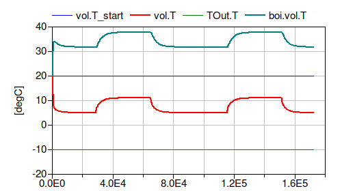
The figure shows that the room temperature is around
5°C when the internal heat gain is zero,
i.e., it is at the average of the outside temperature
and the room design temperature.
Since the boiler control signal is 0.5,
this indicates that the model is correct.
Extends from Modelica.Icons.Example (Icon for runnable examples).
Parameters
| Type | Name | Default | Description |
|---|
| replaceable package MediumA | Buildings.Media.Air | |
| replaceable package MediumW | Buildings.Media.Water | Medium model |
| HeatFlowRate | Q_flow_nominal | 20000 | Nominal heat flow rate of radiator [W] |
| Temperature | TRadSup_nominal | 273.15 + 50 | Radiator nominal supply water temperature [K] |
| Temperature | TRadRet_nominal | 273.15 + 40 | Radiator nominal return water temperature [K] |
| MassFlowRate | mRad_flow_nominal | Q_flow_nominal/4200/(TRadSup... | Radiator nominal mass flow rate [kg/s] |
| Temperature | TBoiSup_nominal | 273.15 + 70 | Boiler nominal supply water temperature [K] |
| Temperature | TBoiRet_min | 273.15 + 60 | Boiler minimum return water temperature [K] |
| MassFlowRate | mBoi_flow_nominal | Q_flow_nominal/4200/(TBoiSup... | Boiler nominal mass flow rate [kg/s] |
| MassFlowRate | mRadVal_flow_nominal | Q_flow_nominal/4200/(TBoiSup... | Radiator nominal mass flow rate [kg/s] |
| Volume | V | 6*10*3 | Room volume [m3] |
| MassFlowRate | mA_flow_nominal | V*1.2*6/3600 | Nominal mass flow rate [kg/s] |
| HeatFlowRate | QRooInt_flow | 4000 | Internal heat gains of the room [W] |
Connectors
| Type | Name | Description |
|---|
| replaceable package MediumA | |
| replaceable package MediumW | Medium model |
Modelica definition
model System3
extends Modelica.Icons.Example;
replaceable package MediumA =
Buildings.Media.Air;
replaceable package MediumW =
Buildings.Media.Water ;
parameter Modelica.SIunits.HeatFlowRate Q_flow_nominal = 20000
;
parameter Modelica.SIunits.Temperature TRadSup_nominal = 273.15+50
;
parameter Modelica.SIunits.Temperature TRadRet_nominal = 273.15+40
;
parameter Modelica.SIunits.MassFlowRate mRad_flow_nominal=
Q_flow_nominal/4200/(TRadSup_nominal-TRadRet_nominal)
;
parameter Modelica.SIunits.Temperature TBoiSup_nominal = 273.15+70
;
parameter Modelica.SIunits.Temperature TBoiRet_min = 273.15+60
;
parameter Modelica.SIunits.MassFlowRate mBoi_flow_nominal=
Q_flow_nominal/4200/(TBoiSup_nominal-TBoiRet_min)
;
parameter Modelica.SIunits.MassFlowRate mRadVal_flow_nominal=
Q_flow_nominal/4200/(TBoiSup_nominal-TRadRet_nominal)
;
Buildings.Fluid.MixingVolumes.MixingVolume vol(
redeclare package Medium =
MediumA,
energyDynamics=Modelica.Fluid.Types.Dynamics.FixedInitial,
m_flow_nominal=mA_flow_nominal,
V=V);
Modelica.Thermal.HeatTransfer.Components.ThermalConductor theCon(G=20000/30)
;
parameter Modelica.SIunits.Volume V=6*10*3 ;
parameter Modelica.SIunits.MassFlowRate mA_flow_nominal = V*1.2*6/3600
;
parameter Modelica.SIunits.HeatFlowRate QRooInt_flow = 4000
;
Modelica.Thermal.HeatTransfer.Sources.FixedTemperature TOut(T=263.15)
;
Modelica.Thermal.HeatTransfer.Sources.PrescribedHeatFlow preHea
;
Modelica.Thermal.HeatTransfer.Components.HeatCapacitor heaCap(C=2*V*1.2*1006)
;
Buildings.Controls.OBC.CDL.Continuous.Sources.TimeTable timTab(
extrapolation=Buildings.Controls.OBC.CDL.Types.Extrapolation.Periodic,
smoothness=Buildings.Controls.OBC.CDL.Types.Smoothness.ConstantSegments,
table=[-6, 0;
8, QRooInt_flow;
18, 0],
timeScale=3600) ;
Buildings.Fluid.HeatExchangers.Radiators.RadiatorEN442_2 rad(
redeclare package Medium =
MediumW,
energyDynamics=Modelica.Fluid.Types.Dynamics.FixedInitial,
Q_flow_nominal=Q_flow_nominal,
T_a_nominal=TRadSup_nominal,
T_b_nominal=TRadRet_nominal) ;
Buildings.Fluid.Sensors.TemperatureTwoPort temSup(
redeclare package Medium =
MediumW,
m_flow_nominal=mRad_flow_nominal) ;
Modelica.Thermal.HeatTransfer.Sensors.TemperatureSensor temRoo
;
Buildings.Fluid.Movers.FlowControlled_m_flow pumRad(
redeclare package Medium =
MediumW,
energyDynamics=Modelica.Fluid.Types.Dynamics.FixedInitial,
m_flow_nominal=mRad_flow_nominal) ;
Buildings.Fluid.FixedResistances.Junction mix(
redeclare package Medium =
MediumW,
energyDynamics=Modelica.Fluid.Types.Dynamics.FixedInitial,
m_flow_nominal={mRadVal_flow_nominal,-mRad_flow_nominal,mRad_flow_nominal
- mRadVal_flow_nominal},
dp_nominal={100,-8000,6750}) ;
Buildings.Fluid.FixedResistances.Junction spl(
redeclare package Medium =
MediumW,
energyDynamics=Modelica.Fluid.Types.Dynamics.FixedInitial,
m_flow_nominal={mBoi_flow_nominal,-mRadVal_flow_nominal,-mBoi_flow_nominal},
dp_nominal={200,-200,-50}) ;
Buildings.Fluid.FixedResistances.Junction spl2(
redeclare package Medium =
MediumW,
energyDynamics=Modelica.Fluid.Types.Dynamics.FixedInitial,
dp_nominal={0,0,0},
m_flow_nominal={mRad_flow_nominal,-mRadVal_flow_nominal,-mRad_flow_nominal
+ mRadVal_flow_nominal});
Buildings.Fluid.FixedResistances.Junction mix2(
redeclare package Medium =
MediumW,
energyDynamics=Modelica.Fluid.Types.Dynamics.FixedInitial,
dp_nominal={0,-200,0},
m_flow_nominal={mRadVal_flow_nominal,-mBoi_flow_nominal,mBoi_flow_nominal})
;
Buildings.Fluid.FixedResistances.Junction spl4(
redeclare package Medium =
MediumW,
energyDynamics=Modelica.Fluid.Types.Dynamics.FixedInitial,
m_flow_nominal=mRadVal_flow_nominal*{1,-1,-1},
dp_nominal=200*{1,-1,-1}) ;
Buildings.Fluid.Movers.FlowControlled_m_flow pumBoi(
redeclare package Medium =
MediumW,
energyDynamics=Modelica.Fluid.Types.Dynamics.FixedInitial,
m_flow_nominal=mBoi_flow_nominal) ;
Buildings.Fluid.Boilers.BoilerPolynomial boi(
redeclare package Medium =
MediumW,
energyDynamics=Modelica.Fluid.Types.Dynamics.FixedInitial,
m_flow_nominal=mBoi_flow_nominal,
dp_nominal=2000,
Q_flow_nominal=Q_flow_nominal,
fue=
Buildings.Fluid.Data.Fuels.HeatingOilLowerHeatingValue()) ;
Buildings.Fluid.Actuators.Valves.ThreeWayEqualPercentageLinear valRad(
redeclare package Medium =
MediumW,
energyDynamics=Modelica.Fluid.Types.Dynamics.FixedInitial,
m_flow_nominal=mRadVal_flow_nominal,
l={0.01,0.01},
dpValve_nominal=6000) ;
Buildings.Fluid.Sources.Boundary_pT preSou(
redeclare package Medium =
MediumW,
nPorts=1)
;
Buildings.Fluid.Actuators.Valves.ThreeWayEqualPercentageLinear valBoi(
redeclare package Medium =
MediumW,
energyDynamics=Modelica.Fluid.Types.Dynamics.FixedInitial,
m_flow_nominal=mBoi_flow_nominal,
l={0.01,0.01},
dpValve_nominal=6000) ;
Buildings.Fluid.Sensors.TemperatureTwoPort temRet(
redeclare package Medium =
MediumW, m_flow_nominal=mBoi_flow_nominal) ;
Buildings.Fluid.FixedResistances.Junction spl1(
redeclare package Medium =
MediumW,
energyDynamics=Modelica.Fluid.Types.Dynamics.FixedInitial,
m_flow_nominal={mBoi_flow_nominal,-mBoi_flow_nominal,-mBoi_flow_nominal},
dp_nominal={0,0,-200}) ;
Buildings.Controls.OBC.CDL.Continuous.Sources.Constant const(k=1)
;
Buildings.Controls.OBC.CDL.Continuous.Sources.Constant conBoi(k=mBoi_flow_nominal)
;
Buildings.Controls.OBC.CDL.Continuous.Sources.Constant const1(k=0.5)
;
Buildings.Controls.OBC.CDL.Continuous.Hysteresis hysPum(
uLow=273.15 + 19,
uHigh=273.15 + 21)
;
Buildings.Controls.OBC.CDL.Conversions.BooleanToReal booToReaRad(realTrue=mRad_flow_nominal)
;
Buildings.Controls.OBC.CDL.Logical.Not not1 ;
equation
connect(TOut.port, theCon.port_a);
connect(theCon.port_b, vol.heatPort);
connect(preHea.port, vol.heatPort);
connect(heaCap.port, vol.heatPort);
connect(timTab.y[1], preHea.Q_flow);
connect(temSup.port_b, rad.port_a);
connect(temRoo.port, vol.heatPort);
connect(rad.heatPortCon, vol.heatPort);
connect(rad.heatPortRad, vol.heatPort);
connect(pumRad.port_b, temSup.port_a);
connect(boi.port_b, pumBoi.port_a);
connect(pumBoi.port_b, spl1.port_1);
connect(spl1.port_2, spl.port_1);
connect(spl.port_2, valRad.port_1);
connect(valRad.port_2, mix.port_1);
connect(spl1.port_3, valBoi.port_3);
connect(valBoi.port_2, temRet.port_a);
connect(temRet.port_b, boi.port_a);
connect(boi.port_a, preSou.ports[1]);
connect(mix2.port_2, valBoi.port_1);
connect(spl4.port_2, mix2.port_1);
connect(spl2.port_2, spl4.port_1);
connect(valRad.port_3, spl4.port_3);
connect(spl.port_3, mix2.port_3);
connect(mix.port_3, spl2.port_3);
connect(mix.port_2, pumRad.port_a);
connect(rad.port_b, spl2.port_1);
connect(const.y, valRad.y);
connect(conBoi.y, pumBoi.m_flow_in);
connect(const.y, valBoi.y);
connect(const1.y, boi.y);
connect(temRoo.T,hysPum. u);
connect(hysPum.y,not1. u);
connect(not1.y,booToReaRad. u);
connect(booToReaRad.y, pumRad.m_flow_in);
end System3;
4th part of the system model, which adds closed-loop control for the pumps and the boiler
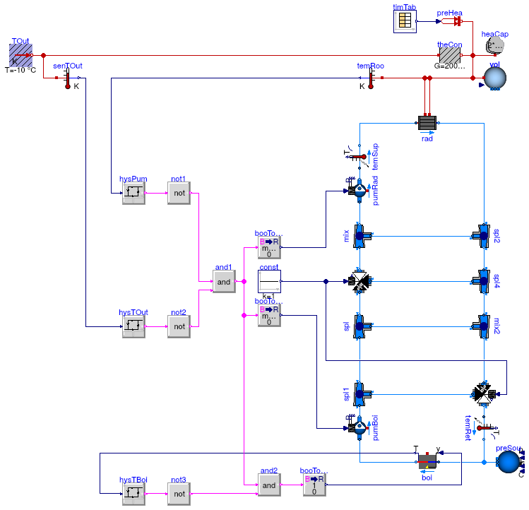
Information
This part of the system model adds to the model that is implemented in
Buildings.Examples.Tutorial.Boiler.System3
closed loop control for the pumps and the boiler.
The control valves are still open loop control.
Implementation
This model was built as follows:
-
First, we copied the model
Buildings.Examples.Tutorial.Boiler.System3
and called it
Buildings.Examples.Tutorial.Boiler.System4.
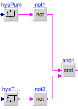
-
Next, we added the outdoor temperature sensor senTOut,
which we will use to disable the plant when the outdoor temperature
is warmer than 17°C.
This is implemented by the instances hysTOut and
not2, whose output signal is connected
to the block and1 as shown in the figure below.
-
Similar to the control of the radiator pump, we used a boolean to real
converter, followed by a first order filter, to set the mass flow
rate of the boiler pump.
-
Next, for the boiler on/off control, we use again a hysteresis block
(instance hysTBoi), which we configured as
  Buildings.Controls.OBC.CDL.Continuous.Hysteresis hysTBoi(uLow=273.15 + 70,
                                                           uHigh=273.15 + 90)
    "Hysteresis for on/off of boiler";
The output of the hysteresis block is sent to the instance
not3, which negates its input signal.
The output signal of the not3 instance is then sent to the
and2 block, which ensures that the boiler is only
on when the pumps are on and the temperature is below
70°C, and that the boiler is off if its temperature reaches 90°C.
Therefore, the boiler control sequence is as shown below.
This completes the closed loop control of the boiler and the pumps.
When simulating the model
for 2 days, or 172800 seconds, the
response shown below should be seen.
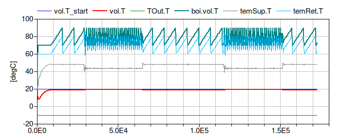
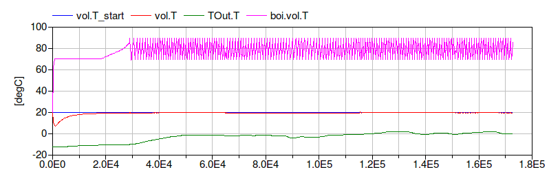
The figure shows that the return water temperature
temRet.T is below
50°C for quite some time when the system heats up.
Furthermore, the supply water temperature
temSup.T is oscillating with the boiler temperature.
We will fix these issues by adding closed loop control for the valves in model
Buildings.Examples.Tutorial.Boiler.System5.
Extends from Modelica.Icons.Example (Icon for runnable examples).
Parameters
| Type | Name | Default | Description |
|---|
| replaceable package MediumA | Buildings.Media.Air | |
| replaceable package MediumW | Buildings.Media.Water | Medium model |
| HeatFlowRate | Q_flow_nominal | 20000 | Nominal heat flow rate of radiator [W] |
| Temperature | TRadSup_nominal | 273.15 + 50 | Radiator nominal supply water temperature [K] |
| Temperature | TRadRet_nominal | 273.15 + 40 | Radiator nominal return water temperature [K] |
| MassFlowRate | mRad_flow_nominal | Q_flow_nominal/4200/(TRadSup... | Radiator nominal mass flow rate [kg/s] |
| Temperature | TBoiSup_nominal | 273.15 + 70 | Boiler nominal supply water temperature [K] |
| Temperature | TBoiRet_min | 273.15 + 60 | Boiler minimum return water temperature [K] |
| MassFlowRate | mBoi_flow_nominal | Q_flow_nominal/4200/(TBoiSup... | Boiler nominal mass flow rate [kg/s] |
| MassFlowRate | mRadVal_flow_nominal | Q_flow_nominal/4200/(TBoiSup... | Radiator nominal mass flow rate [kg/s] |
| Volume | V | 6*10*3 | Room volume [m3] |
| MassFlowRate | mA_flow_nominal | V*1.2*6/3600 | Nominal mass flow rate [kg/s] |
| HeatFlowRate | QRooInt_flow | 4000 | Internal heat gains of the room [W] |
Connectors
| Type | Name | Description |
|---|
| replaceable package MediumA | |
| replaceable package MediumW | Medium model |
Modelica definition
model System4
extends Modelica.Icons.Example;
replaceable package MediumA =
Buildings.Media.Air;
replaceable package MediumW =
Buildings.Media.Water ;
parameter Modelica.SIunits.HeatFlowRate Q_flow_nominal = 20000
;
parameter Modelica.SIunits.Temperature TRadSup_nominal = 273.15+50
;
parameter Modelica.SIunits.Temperature TRadRet_nominal = 273.15+40
;
parameter Modelica.SIunits.MassFlowRate mRad_flow_nominal=
Q_flow_nominal/4200/(TRadSup_nominal-TRadRet_nominal)
;
parameter Modelica.SIunits.Temperature TBoiSup_nominal = 273.15+70
;
parameter Modelica.SIunits.Temperature TBoiRet_min = 273.15+60
;
parameter Modelica.SIunits.MassFlowRate mBoi_flow_nominal=
Q_flow_nominal/4200/(TBoiSup_nominal-TBoiRet_min)
;
parameter Modelica.SIunits.MassFlowRate mRadVal_flow_nominal=
Q_flow_nominal/4200/(TBoiSup_nominal-TRadRet_nominal)
;
Buildings.Fluid.MixingVolumes.MixingVolume vol(
redeclare package Medium =
MediumA,
energyDynamics=Modelica.Fluid.Types.Dynamics.FixedInitial,
m_flow_nominal=mA_flow_nominal,
V=V);
Modelica.Thermal.HeatTransfer.Components.ThermalConductor theCon(G=20000/30)
;
parameter Modelica.SIunits.Volume V=6*10*3 ;
parameter Modelica.SIunits.MassFlowRate mA_flow_nominal = V*1.2*6/3600
;
parameter Modelica.SIunits.HeatFlowRate QRooInt_flow = 4000
;
Modelica.Thermal.HeatTransfer.Sources.FixedTemperature TOut(T=263.15)
;
Modelica.Thermal.HeatTransfer.Sources.PrescribedHeatFlow preHea
;
Modelica.Thermal.HeatTransfer.Components.HeatCapacitor heaCap(C=2*V*1.2*1006)
;
Buildings.Controls.OBC.CDL.Continuous.Sources.TimeTable timTab(
extrapolation=Buildings.Controls.OBC.CDL.Types.Extrapolation.Periodic,
smoothness=Buildings.Controls.OBC.CDL.Types.Smoothness.ConstantSegments,
table=[-6, 0;
8, QRooInt_flow;
18, 0],
timeScale=3600) ;
Buildings.Fluid.HeatExchangers.Radiators.RadiatorEN442_2 rad(
redeclare package Medium =
MediumW,
energyDynamics=Modelica.Fluid.Types.Dynamics.FixedInitial,
Q_flow_nominal=Q_flow_nominal,
T_a_nominal=TRadSup_nominal,
T_b_nominal=TRadRet_nominal) ;
Buildings.Fluid.Sensors.TemperatureTwoPort temSup(
redeclare package Medium =
MediumW,
m_flow_nominal=mRad_flow_nominal) ;
Modelica.Thermal.HeatTransfer.Sensors.TemperatureSensor temRoo
;
Buildings.Fluid.Movers.FlowControlled_m_flow pumRad(
redeclare package Medium =
MediumW,
energyDynamics=Modelica.Fluid.Types.Dynamics.FixedInitial,
m_flow_nominal=mRad_flow_nominal) ;
Buildings.Fluid.FixedResistances.Junction mix(
redeclare package Medium =
MediumW,
energyDynamics=Modelica.Fluid.Types.Dynamics.FixedInitial,
m_flow_nominal={mRadVal_flow_nominal,-mRad_flow_nominal,mRad_flow_nominal
- mRadVal_flow_nominal},
dp_nominal={100,-8000,6750}) ;
Buildings.Fluid.FixedResistances.Junction spl(
redeclare package Medium =
MediumW,
energyDynamics=Modelica.Fluid.Types.Dynamics.FixedInitial,
m_flow_nominal={mBoi_flow_nominal,-mRadVal_flow_nominal,-mBoi_flow_nominal},
dp_nominal={200,-200,-50}) ;
Buildings.Fluid.FixedResistances.Junction spl2(
redeclare package Medium =
MediumW,
energyDynamics=Modelica.Fluid.Types.Dynamics.FixedInitial,
dp_nominal={0,0,0},
m_flow_nominal={mRad_flow_nominal,-mRadVal_flow_nominal,-mRad_flow_nominal
+ mRadVal_flow_nominal});
Buildings.Fluid.FixedResistances.Junction mix2(
redeclare package Medium =
MediumW,
energyDynamics=Modelica.Fluid.Types.Dynamics.FixedInitial,
dp_nominal={0,-200,0},
m_flow_nominal={mRadVal_flow_nominal,-mBoi_flow_nominal,mBoi_flow_nominal})
;
Buildings.Fluid.FixedResistances.Junction spl4(
redeclare package Medium =
MediumW,
energyDynamics=Modelica.Fluid.Types.Dynamics.FixedInitial,
m_flow_nominal=mRadVal_flow_nominal*{1,-1,-1},
dp_nominal=200*{1,-1,-1}) ;
Buildings.Fluid.Movers.FlowControlled_m_flow pumBoi(
redeclare package Medium =
MediumW,
energyDynamics=Modelica.Fluid.Types.Dynamics.FixedInitial,
m_flow_nominal=mBoi_flow_nominal) ;
Buildings.Fluid.Boilers.BoilerPolynomial boi(
redeclare package Medium =
MediumW,
energyDynamics=Modelica.Fluid.Types.Dynamics.FixedInitial,
m_flow_nominal=mBoi_flow_nominal,
dp_nominal=2000,
Q_flow_nominal=Q_flow_nominal,
fue=
Buildings.Fluid.Data.Fuels.HeatingOilLowerHeatingValue()) ;
Buildings.Fluid.Actuators.Valves.ThreeWayEqualPercentageLinear valRad(
redeclare package Medium =
MediumW,
energyDynamics=Modelica.Fluid.Types.Dynamics.FixedInitial,
m_flow_nominal=mRadVal_flow_nominal,
l={0.01,0.01},
dpValve_nominal=6000) ;
Buildings.Fluid.Sources.Boundary_pT preSou(
redeclare package Medium =
MediumW,
nPorts=1)
;
Buildings.Fluid.Actuators.Valves.ThreeWayEqualPercentageLinear valBoi(
redeclare package Medium =
MediumW,
energyDynamics=Modelica.Fluid.Types.Dynamics.FixedInitial,
m_flow_nominal=mBoi_flow_nominal,
l={0.01,0.01},
dpValve_nominal=6000) ;
Buildings.Fluid.Sensors.TemperatureTwoPort temRet(
redeclare package Medium =
MediumW, m_flow_nominal=mBoi_flow_nominal) ;
Buildings.Fluid.FixedResistances.Junction spl1(
redeclare package Medium =
MediumW,
energyDynamics=Modelica.Fluid.Types.Dynamics.FixedInitial,
m_flow_nominal={mBoi_flow_nominal,-mBoi_flow_nominal,-mBoi_flow_nominal},
dp_nominal={0,0,-200}) ;
Buildings.Controls.OBC.CDL.Continuous.Sources.Constant const(k=1)
;
Buildings.Controls.OBC.CDL.Continuous.Hysteresis hysTOut(uLow=273.15 + 16, uHigh=273.15 + 17)
;
Buildings.Controls.OBC.CDL.Logical.Not not2;
Modelica.Thermal.HeatTransfer.Sensors.TemperatureSensor senTOut
;
Buildings.Controls.OBC.CDL.Continuous.Hysteresis hysTBoi(uHigh=273.15 + 90,
uLow=273.15 + 70)
;
Buildings.Controls.OBC.CDL.Logical.Not not3;
Buildings.Controls.OBC.CDL.Logical.And and1;
Buildings.Controls.OBC.CDL.Conversions.BooleanToReal booToReaRad1(realTrue=mBoi_flow_nominal)
;
Buildings.Controls.OBC.CDL.Logical.And and2;
Buildings.Controls.OBC.CDL.Conversions.BooleanToReal booToReaRad2(realTrue=1) ;
Buildings.Controls.OBC.CDL.Continuous.Hysteresis hysPum(
uLow=273.15 + 19,
uHigh=273.15 + 21)
;
Buildings.Controls.OBC.CDL.Conversions.BooleanToReal booToReaRad(realTrue=mRad_flow_nominal)
;
Buildings.Controls.OBC.CDL.Logical.Not not1 ;
equation
connect(TOut.port, theCon.port_a);
connect(theCon.port_b, vol.heatPort);
connect(preHea.port, vol.heatPort);
connect(heaCap.port, vol.heatPort);
connect(timTab.y[1], preHea.Q_flow);
connect(temSup.port_b, rad.port_a);
connect(temRoo.port, vol.heatPort);
connect(rad.heatPortCon, vol.heatPort);
connect(rad.heatPortRad, vol.heatPort);
connect(pumRad.port_b, temSup.port_a);
connect(boi.port_b, pumBoi.port_a);
connect(pumBoi.port_b, spl1.port_1);
connect(spl1.port_2, spl.port_1);
connect(spl.port_2, valRad.port_1);
connect(valRad.port_2, mix.port_1);
connect(spl1.port_3, valBoi.port_3);
connect(valBoi.port_2, temRet.port_a);
connect(temRet.port_b, boi.port_a);
connect(boi.port_a, preSou.ports[1]);
connect(mix2.port_2, valBoi.port_1);
connect(spl4.port_2, mix2.port_1);
connect(spl2.port_2, spl4.port_1);
connect(valRad.port_3, spl4.port_3);
connect(spl.port_3, mix2.port_3);
connect(mix.port_3, spl2.port_3);
connect(mix.port_2, pumRad.port_a);
connect(rad.port_b, spl2.port_1);
connect(const.y, valRad.y);
connect(const.y, valBoi.y);
connect(hysTOut.y, not2.u);
connect(senTOut.port, TOut.port);
connect(hysTBoi.y, not3.u);
connect(not2.y, and1.u2);
connect(boi.T, hysTBoi.u);
connect(senTOut.T, hysTOut.u);
connect(and1.y, booToReaRad1.u);
connect(and1.y, and2.u1);
connect(not3.y, and2.u2);
connect(and2.y, booToReaRad2.u);
connect(booToReaRad2.y, boi.y);
connect(temRoo.T,hysPum. u);
connect(hysPum.y,not1. u);
connect(not1.y, and1.u1);
connect(and1.y, booToReaRad.u);
connect(booToReaRad.y, pumRad.m_flow_in);
connect(booToReaRad1.y, pumBoi.m_flow_in);
end System4;
5th part of the system model, which adds closed-loop control for the valves
Information
This part of the system model adds to the model that is implemented in
Buildings.Examples.Tutorial.Boiler.System4
closed loop control for the valves.
Implementation
This model was built as follows:
-
First, we copied the model
Buildings.Examples.Tutorial.Boiler.System4
and called it
Buildings.Examples.Tutorial.Boiler.System5.
-
Next, we added closed loop control for the boiler valve as
shown in the figure below.
This is implemented using the constant block
Buildings.Controls.OBC.CDL.Continuous.Sources.Constant for the set point,
the PID controller with output limitation
Buildings.Controls.OBC.CDL.Continuous.PID.
We configured the controller as
  Buildings.Controls.OBC.CDL.Continuous.PID conPIDBoi(
    controllerType=Buildings.Controls.OBC.CDL.Types.SimpleController.P,
    k=0.1,
    Ti=120,
    Td=1,
    reverseActing=false) "Controller for valve in boiler loop";
We set the proportional band to 10 Kelvin, hence k=0.1.
We set the integral time constant to 120 seconds, which is
the same time as is required to open or close the valve.
These settings turn out to give satisfactory closed loop control performance.
Otherwise, we would need to retune the controller, which is
usually easiest by configuring the controller as a P-controller, then tuning the
proportional gain, and finally changing it to a PI-controller and tuning the
integral time constant.
Note that we also set reverseActing=false because
if, for a constant set point, the measured
temperature increases, the valve control signal needs to decrease towards y=0,
because in this condition, the boiler inlet temperature is not yet high enough.
Once it is high enough, the control error will be negative and the valve
can open.
-
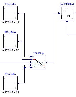
The valve control for the radiator loop is implemented similar to
the boiler loop, with the exception that the setpoint is computed
using the model
Buildings.Controls.OBC.CDL.Continuous.Line to implement
a set point that shifts as a function of the room temperature.
This instance is called TSetSup in the
control sequence shown in the figure below, and takes as an input
the room temperature, and the points for the
(x1, f1) and
(x2, f2) coordinates through which the setpoint
goes.
This completes the closed loop control.
When simulating the model
for 2 days, or 172800 seconds, the
response shown below should be seen.
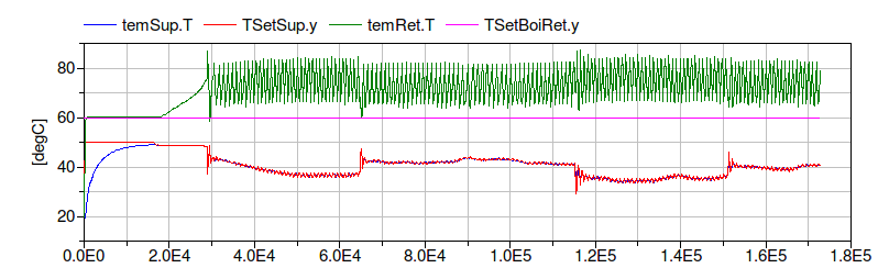
The figure shows that the return water temperature
temRet.T
quickly raises to 50°C and the supply water temperature
temSup.T
has smaller oscillations compared to
Buildings.Examples.Tutorial.Boiler.System4.
Extends from Modelica.Icons.Example (Icon for runnable examples).
Parameters
| Type | Name | Default | Description |
|---|
| replaceable package MediumA | Buildings.Media.Air | |
| replaceable package MediumW | Buildings.Media.Water | Medium model |
| HeatFlowRate | Q_flow_nominal | 20000 | Nominal heat flow rate of radiator [W] |
| Temperature | TRadSup_nominal | 273.15 + 50 | Radiator nominal supply water temperature [K] |
| Temperature | TRadRet_nominal | 273.15 + 40 | Radiator nominal return water temperature [K] |
| MassFlowRate | mRad_flow_nominal | Q_flow_nominal/4200/(TRadSup... | Radiator nominal mass flow rate [kg/s] |
| Temperature | TBoiSup_nominal | 273.15 + 70 | Boiler nominal supply water temperature [K] |
| Temperature | TBoiRet_min | 273.15 + 60 | Boiler minimum return water temperature [K] |
| MassFlowRate | mBoi_flow_nominal | Q_flow_nominal/4200/(TBoiSup... | Boiler nominal mass flow rate [kg/s] |
| MassFlowRate | mRadVal_flow_nominal | Q_flow_nominal/4200/(TBoiSup... | Radiator nominal mass flow rate [kg/s] |
| Volume | V | 6*10*3 | Room volume [m3] |
| MassFlowRate | mA_flow_nominal | V*1.2*6/3600 | Nominal mass flow rate [kg/s] |
| HeatFlowRate | QRooInt_flow | 4000 | Internal heat gains of the room [W] |
Connectors
| Type | Name | Description |
|---|
| replaceable package MediumA | |
| replaceable package MediumW | Medium model |
Modelica definition
model System5
extends Modelica.Icons.Example;
replaceable package MediumA =
Buildings.Media.Air;
replaceable package MediumW =
Buildings.Media.Water ;
parameter Modelica.SIunits.HeatFlowRate Q_flow_nominal = 20000
;
parameter Modelica.SIunits.Temperature TRadSup_nominal = 273.15+50
;
parameter Modelica.SIunits.Temperature TRadRet_nominal = 273.15+40
;
parameter Modelica.SIunits.MassFlowRate mRad_flow_nominal=
Q_flow_nominal/4200/(TRadSup_nominal-TRadRet_nominal)
;
parameter Modelica.SIunits.Temperature TBoiSup_nominal = 273.15+70
;
parameter Modelica.SIunits.Temperature TBoiRet_min = 273.15+60
;
parameter Modelica.SIunits.MassFlowRate mBoi_flow_nominal=
Q_flow_nominal/4200/(TBoiSup_nominal-TBoiRet_min)
;
parameter Modelica.SIunits.MassFlowRate mRadVal_flow_nominal=
Q_flow_nominal/4200/(TBoiSup_nominal-TRadRet_nominal)
;
Buildings.Fluid.MixingVolumes.MixingVolume vol(
redeclare package Medium =
MediumA,
energyDynamics=Modelica.Fluid.Types.Dynamics.FixedInitial,
m_flow_nominal=mA_flow_nominal,
V=V);
Modelica.Thermal.HeatTransfer.Components.ThermalConductor theCon(G=20000/30)
;
parameter Modelica.SIunits.Volume V=6*10*3 ;
parameter Modelica.SIunits.MassFlowRate mA_flow_nominal = V*1.2*6/3600
;
parameter Modelica.SIunits.HeatFlowRate QRooInt_flow = 4000
;
Modelica.Thermal.HeatTransfer.Sources.FixedTemperature TOut(T=263.15)
;
Modelica.Thermal.HeatTransfer.Sources.PrescribedHeatFlow preHea
;
Modelica.Thermal.HeatTransfer.Components.HeatCapacitor heaCap(C=2*V*1.2*1006)
;
Buildings.Controls.OBC.CDL.Continuous.Sources.TimeTable timTab(
extrapolation=Buildings.Controls.OBC.CDL.Types.Extrapolation.Periodic,
smoothness=Buildings.Controls.OBC.CDL.Types.Smoothness.ConstantSegments,
table=[-6, 0;
8, QRooInt_flow;
18, 0],
timeScale=3600) ;
Buildings.Fluid.HeatExchangers.Radiators.RadiatorEN442_2 rad(
redeclare package Medium =
MediumW,
energyDynamics=Modelica.Fluid.Types.Dynamics.FixedInitial,
Q_flow_nominal=Q_flow_nominal,
T_a_nominal=TRadSup_nominal,
T_b_nominal=TRadRet_nominal) ;
Buildings.Fluid.Sensors.TemperatureTwoPort temSup(
redeclare package Medium =
MediumW,
m_flow_nominal=mRad_flow_nominal) ;
Modelica.Thermal.HeatTransfer.Sensors.TemperatureSensor temRoo
;
Buildings.Fluid.Movers.FlowControlled_m_flow pumRad(
redeclare package Medium =
MediumW,
energyDynamics=Modelica.Fluid.Types.Dynamics.FixedInitial,
m_flow_nominal=mRad_flow_nominal) ;
Buildings.Fluid.FixedResistances.Junction mix(
redeclare package Medium =
MediumW,
energyDynamics=Modelica.Fluid.Types.Dynamics.FixedInitial,
m_flow_nominal={mRadVal_flow_nominal,-mRad_flow_nominal,mRad_flow_nominal
- mRadVal_flow_nominal},
dp_nominal={100,-8000,6750}) ;
Buildings.Fluid.FixedResistances.Junction spl(
redeclare package Medium =
MediumW,
energyDynamics=Modelica.Fluid.Types.Dynamics.FixedInitial,
m_flow_nominal={mBoi_flow_nominal,-mRadVal_flow_nominal,-mBoi_flow_nominal},
dp_nominal={200,-200,-50}) ;
Buildings.Fluid.FixedResistances.Junction spl2(
redeclare package Medium =
MediumW,
energyDynamics=Modelica.Fluid.Types.Dynamics.FixedInitial,
dp_nominal={0,0,0},
m_flow_nominal={mRad_flow_nominal,-mRadVal_flow_nominal,-mRad_flow_nominal
+ mRadVal_flow_nominal});
Buildings.Fluid.FixedResistances.Junction mix2(
redeclare package Medium =
MediumW,
energyDynamics=Modelica.Fluid.Types.Dynamics.FixedInitial,
dp_nominal={0,-200,0},
m_flow_nominal={mRadVal_flow_nominal,-mBoi_flow_nominal,mBoi_flow_nominal})
;
Buildings.Fluid.FixedResistances.Junction spl4(
redeclare package Medium =
MediumW,
energyDynamics=Modelica.Fluid.Types.Dynamics.FixedInitial,
m_flow_nominal=mRadVal_flow_nominal*{1,-1,-1},
dp_nominal=200*{1,-1,-1}) ;
Buildings.Fluid.Movers.FlowControlled_m_flow pumBoi(
redeclare package Medium =
MediumW,
energyDynamics=Modelica.Fluid.Types.Dynamics.FixedInitial,
m_flow_nominal=mBoi_flow_nominal) ;
Buildings.Fluid.Boilers.BoilerPolynomial boi(
redeclare package Medium =
MediumW,
energyDynamics=Modelica.Fluid.Types.Dynamics.FixedInitial,
m_flow_nominal=mBoi_flow_nominal,
dp_nominal=2000,
Q_flow_nominal=Q_flow_nominal,
fue=
Buildings.Fluid.Data.Fuels.HeatingOilLowerHeatingValue()) ;
Buildings.Fluid.Actuators.Valves.ThreeWayEqualPercentageLinear valRad(
redeclare package Medium =
MediumW,
energyDynamics=Modelica.Fluid.Types.Dynamics.FixedInitial,
m_flow_nominal=mRadVal_flow_nominal,
l={0.01,0.01},
dpValve_nominal=6000) ;
Buildings.Fluid.Sources.Boundary_pT preSou(
redeclare package Medium =
MediumW,
nPorts=1)
;
Buildings.Fluid.Actuators.Valves.ThreeWayEqualPercentageLinear valBoi(
redeclare package Medium =
MediumW,
energyDynamics=Modelica.Fluid.Types.Dynamics.FixedInitial,
m_flow_nominal=mBoi_flow_nominal,
l={0.01,0.01},
dpValve_nominal=6000) ;
Buildings.Fluid.Sensors.TemperatureTwoPort temRet(
redeclare package Medium =
MediumW, m_flow_nominal=mBoi_flow_nominal) ;
Buildings.Fluid.FixedResistances.Junction spl1(
redeclare package Medium =
MediumW,
energyDynamics=Modelica.Fluid.Types.Dynamics.FixedInitial,
m_flow_nominal={mBoi_flow_nominal,-mBoi_flow_nominal,-mBoi_flow_nominal},
dp_nominal={0,0,-200}) ;
Buildings.Controls.OBC.CDL.Continuous.Hysteresis hysTOut(uLow=273.15 + 16, uHigh=273.15 + 17)
;
Buildings.Controls.OBC.CDL.Logical.Not not2;
Modelica.Thermal.HeatTransfer.Sensors.TemperatureSensor senTOut
;
Buildings.Controls.OBC.CDL.Continuous.Hysteresis hysTBoi(uHigh=273.15 + 90,
uLow=273.15 + 70)
;
Buildings.Controls.OBC.CDL.Logical.Not not3;
Buildings.Controls.OBC.CDL.Logical.And and1;
Buildings.Controls.OBC.CDL.Conversions.BooleanToReal booToReaRad1(realTrue=mBoi_flow_nominal)
;
Buildings.Controls.OBC.CDL.Logical.And and2;
Buildings.Controls.OBC.CDL.Conversions.BooleanToReal booToReaRad2(realTrue=1) ;
Buildings.Controls.OBC.CDL.Continuous.Hysteresis hysPum(
uLow=273.15 + 19,
uHigh=273.15 + 21)
;
Buildings.Controls.OBC.CDL.Conversions.BooleanToReal booToReaRad(realTrue=mRad_flow_nominal)
;
Buildings.Controls.OBC.CDL.Logical.Not not1 ;
Buildings.Controls.OBC.CDL.Continuous.Sources.Constant TSetBoiRet(k=TBoiRet_min)
;
Buildings.Controls.OBC.CDL.Continuous.PID conPIDBoi(
Td=1,
Ti=120,
controllerType=Buildings.Controls.OBC.CDL.Types.SimpleController.PI,
k=0.1,
reverseActing=false) ;
Buildings.Controls.OBC.CDL.Continuous.PID conPIDRad(
Td=1,
Ti=120,
controllerType=Buildings.Controls.OBC.CDL.Types.SimpleController.PI,
k=0.1) ;
Buildings.Controls.OBC.CDL.Continuous.Line TSetSup
;
Buildings.Controls.OBC.CDL.Continuous.Sources.Constant TSupMin(k=273.15 + 21)
;
Buildings.Controls.OBC.CDL.Continuous.Sources.Constant TSupMax(k=273.15 + 50)
;
Buildings.Controls.OBC.CDL.Continuous.Sources.Constant TRooMin(k=273.15 + 19)
;
equation
connect(TOut.port, theCon.port_a);
connect(theCon.port_b, vol.heatPort);
connect(preHea.port, vol.heatPort);
connect(heaCap.port, vol.heatPort);
connect(timTab.y[1], preHea.Q_flow);
connect(temSup.port_b, rad.port_a);
connect(temRoo.port, vol.heatPort);
connect(rad.heatPortCon, vol.heatPort);
connect(rad.heatPortRad, vol.heatPort);
connect(pumRad.port_b, temSup.port_a);
connect(boi.port_b, pumBoi.port_a);
connect(pumBoi.port_b, spl1.port_1);
connect(spl1.port_2, spl.port_1);
connect(spl.port_2, valRad.port_1);
connect(valRad.port_2, mix.port_1);
connect(spl1.port_3, valBoi.port_3);
connect(valBoi.port_2, temRet.port_a);
connect(temRet.port_b, boi.port_a);
connect(boi.port_a, preSou.ports[1]);
connect(mix2.port_2, valBoi.port_1);
connect(spl4.port_2, mix2.port_1);
connect(spl2.port_2, spl4.port_1);
connect(valRad.port_3, spl4.port_3);
connect(spl.port_3, mix2.port_3);
connect(mix.port_3, spl2.port_3);
connect(mix.port_2, pumRad.port_a);
connect(rad.port_b, spl2.port_1);
connect(hysTOut.y, not2.u);
connect(senTOut.port, TOut.port);
connect(hysTBoi.y, not3.u);
connect(not2.y, and1.u2);
connect(boi.T, hysTBoi.u);
connect(senTOut.T, hysTOut.u);
connect(and1.y, booToReaRad1.u);
connect(and1.y, and2.u1);
connect(not3.y, and2.u2);
connect(and2.y, booToReaRad2.u);
connect(booToReaRad2.y, boi.y);
connect(temRoo.T,hysPum. u);
connect(hysPum.y,not1. u);
connect(not1.y, and1.u1);
connect(and1.y, booToReaRad.u);
connect(temSup.T, conPIDRad.u_m);
connect(conPIDRad.y, valRad.y);
connect(booToReaRad.y, pumRad.m_flow_in);
connect(booToReaRad1.y, pumBoi.m_flow_in);
connect(conPIDBoi.y, valBoi.y);
connect(TSetBoiRet.y, conPIDBoi.u_s);
connect(temRet.T, conPIDBoi.u_m);
connect(conPIDRad.u_s, TSetSup.y);
connect(TSetSup.x1, TRooMin.y);
connect(TSupMax.y, TSetSup.f1);
connect(TSupMin.y, TSetSup.f2);
connect(TSupMin.y, TSetSup.x2);
connect(TSetSup.u, temRoo.T);
end System5;
6th part of the system model, which adds weather data and changes to PI control
Information
This part of the system model adds to the model that is implemented in
Buildings.Examples.Tutorial.Boiler.System5
weather data, and it changes the control to PI control.
Implementation
This model was built as follows:
-
First, we copied the model
Buildings.Examples.Tutorial.Boiler.System5
and called it
Buildings.Examples.Tutorial.Boiler.System6.
-
Next, we added the weather data as shown in the figure below.
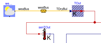
The weather data reader is implemented using
  BoundaryConditions.WeatherData.ReaderTMY3 weaDat(
    filNam="modelica://Buildings/Resources/weatherdata/USA_IL_Chicago-OHare.Intl.AP.725300_TMY3.mos")
    "Weather data reader";
The yellow icon in the middle of the figure is an instance of
Buildings.BoundaryConditions.WeatherData.Bus.
This is required to extract the dry bulb temperature from the weather data bus.
Note that we changed the instance TOut from
Modelica.Thermal.HeatTransfer.Sources.FixedTemperature
to
Modelica.Thermal.HeatTransfer.Sources.PrescribedTemperature
in order to use the dry-bulb temperature as an input signal.
This completes the closed loop control.
When simulating the model
for 2 days, or 172800 seconds, the
response shown below should be seen.
The figure shows that the boiler temperature is regulated between
70°C and
90°C,
that
the boiler inlet temperature is above
60°C,
and that the room temperature and the supply water temperature are
maintained at their set point.
Extends from Modelica.Icons.Example (Icon for runnable examples).
Parameters
| Type | Name | Default | Description |
|---|
| replaceable package MediumA | Buildings.Media.Air | |
| replaceable package MediumW | Buildings.Media.Water | Medium model |
| HeatFlowRate | Q_flow_nominal | 20000 | Nominal heat flow rate of radiator [W] |
| Temperature | TRadSup_nominal | 273.15 + 50 | Radiator nominal supply water temperature [K] |
| Temperature | TRadRet_nominal | 273.15 + 40 | Radiator nominal return water temperature [K] |
| MassFlowRate | mRad_flow_nominal | Q_flow_nominal/4200/(TRadSup... | Radiator nominal mass flow rate [kg/s] |
| Temperature | TBoiSup_nominal | 273.15 + 70 | Boiler nominal supply water temperature [K] |
| Temperature | TBoiRet_min | 273.15 + 60 | Boiler minimum return water temperature [K] |
| MassFlowRate | mBoi_flow_nominal | Q_flow_nominal/4200/(TBoiSup... | Boiler nominal mass flow rate [kg/s] |
| MassFlowRate | mRadVal_flow_nominal | Q_flow_nominal/4200/(TBoiSup... | Radiator nominal mass flow rate [kg/s] |
| Volume | V | 6*10*3 | Room volume [m3] |
| MassFlowRate | mA_flow_nominal | V*1.2*6/3600 | Nominal mass flow rate [kg/s] |
| HeatFlowRate | QRooInt_flow | 4000 | Internal heat gains of the room [W] |
Connectors
| Type | Name | Description |
|---|
| replaceable package MediumA | |
| replaceable package MediumW | Medium model |
| Bus | weaBus | |
Modelica definition
model System6
extends Modelica.Icons.Example;
replaceable package MediumA =
Buildings.Media.Air;
replaceable package MediumW =
Buildings.Media.Water ;
parameter Modelica.SIunits.HeatFlowRate Q_flow_nominal = 20000
;
parameter Modelica.SIunits.Temperature TRadSup_nominal = 273.15+50
;
parameter Modelica.SIunits.Temperature TRadRet_nominal = 273.15+40
;
parameter Modelica.SIunits.MassFlowRate mRad_flow_nominal=
Q_flow_nominal/4200/(TRadSup_nominal-TRadRet_nominal)
;
parameter Modelica.SIunits.Temperature TBoiSup_nominal = 273.15+70
;
parameter Modelica.SIunits.Temperature TBoiRet_min = 273.15+60
;
parameter Modelica.SIunits.MassFlowRate mBoi_flow_nominal=
Q_flow_nominal/4200/(TBoiSup_nominal-TBoiRet_min)
;
parameter Modelica.SIunits.MassFlowRate mRadVal_flow_nominal=
Q_flow_nominal/4200/(TBoiSup_nominal-TRadRet_nominal)
;
Buildings.Fluid.MixingVolumes.MixingVolume vol(
redeclare package Medium =
MediumA,
energyDynamics=Modelica.Fluid.Types.Dynamics.FixedInitial,
m_flow_nominal=mA_flow_nominal,
V=V);
Modelica.Thermal.HeatTransfer.Components.ThermalConductor theCon(G=20000/30)
;
parameter Modelica.SIunits.Volume V=6*10*3 ;
parameter Modelica.SIunits.MassFlowRate mA_flow_nominal = V*1.2*6/3600
;
parameter Modelica.SIunits.HeatFlowRate QRooInt_flow = 4000
;
Modelica.Thermal.HeatTransfer.Sources.PrescribedHeatFlow preHea
;
Modelica.Thermal.HeatTransfer.Components.HeatCapacitor heaCap(C=2*V*1.2*1006)
;
Buildings.Controls.OBC.CDL.Continuous.Sources.TimeTable timTab(
extrapolation=Buildings.Controls.OBC.CDL.Types.Extrapolation.Periodic,
smoothness=Buildings.Controls.OBC.CDL.Types.Smoothness.ConstantSegments,
table=[-6, 0;
8, QRooInt_flow;
18, 0],
timeScale=3600) ;
Buildings.Fluid.HeatExchangers.Radiators.RadiatorEN442_2 rad(
redeclare package Medium =
MediumW,
energyDynamics=Modelica.Fluid.Types.Dynamics.FixedInitial,
Q_flow_nominal=Q_flow_nominal,
T_a_nominal=TRadSup_nominal,
T_b_nominal=TRadRet_nominal) ;
Buildings.Fluid.Sensors.TemperatureTwoPort temSup(
redeclare package Medium =
MediumW,
m_flow_nominal=mRad_flow_nominal) ;
Modelica.Thermal.HeatTransfer.Sensors.TemperatureSensor temRoo
;
Buildings.Fluid.Movers.FlowControlled_m_flow pumRad(
redeclare package Medium =
MediumW,
energyDynamics=Modelica.Fluid.Types.Dynamics.FixedInitial,
m_flow_nominal=mRad_flow_nominal) ;
Buildings.Fluid.FixedResistances.Junction mix(
redeclare package Medium =
MediumW,
energyDynamics=Modelica.Fluid.Types.Dynamics.FixedInitial,
m_flow_nominal={mRadVal_flow_nominal,-mRad_flow_nominal,mRad_flow_nominal
- mRadVal_flow_nominal},
dp_nominal={100,-8000,6750}) ;
Buildings.Fluid.FixedResistances.Junction spl(
redeclare package Medium =
MediumW,
energyDynamics=Modelica.Fluid.Types.Dynamics.FixedInitial,
m_flow_nominal={mBoi_flow_nominal,-mRadVal_flow_nominal,-mBoi_flow_nominal},
dp_nominal={200,-200,-50}) ;
Buildings.Fluid.FixedResistances.Junction spl2(
redeclare package Medium =
MediumW,
energyDynamics=Modelica.Fluid.Types.Dynamics.FixedInitial,
dp_nominal={0,0,0},
m_flow_nominal={mRad_flow_nominal,-mRadVal_flow_nominal,-mRad_flow_nominal
+ mRadVal_flow_nominal});
Buildings.Fluid.FixedResistances.Junction mix2(
redeclare package Medium =
MediumW,
energyDynamics=Modelica.Fluid.Types.Dynamics.FixedInitial,
dp_nominal={0,-200,0},
m_flow_nominal={mRadVal_flow_nominal,-mBoi_flow_nominal,mBoi_flow_nominal})
;
Buildings.Fluid.FixedResistances.Junction spl4(
redeclare package Medium =
MediumW,
energyDynamics=Modelica.Fluid.Types.Dynamics.FixedInitial,
m_flow_nominal=mRadVal_flow_nominal*{1,-1,-1},
dp_nominal=200*{1,-1,-1}) ;
Buildings.Fluid.Movers.FlowControlled_m_flow pumBoi(
redeclare package Medium =
MediumW,
energyDynamics=Modelica.Fluid.Types.Dynamics.FixedInitial,
m_flow_nominal=mBoi_flow_nominal) ;
Buildings.Fluid.Boilers.BoilerPolynomial boi(
redeclare package Medium =
MediumW,
energyDynamics=Modelica.Fluid.Types.Dynamics.FixedInitial,
m_flow_nominal=mBoi_flow_nominal,
dp_nominal=2000,
Q_flow_nominal=Q_flow_nominal,
fue=
Buildings.Fluid.Data.Fuels.HeatingOilLowerHeatingValue()) ;
Buildings.Fluid.Actuators.Valves.ThreeWayEqualPercentageLinear valRad(
redeclare package Medium =
MediumW,
energyDynamics=Modelica.Fluid.Types.Dynamics.FixedInitial,
m_flow_nominal=mRadVal_flow_nominal,
l={0.01,0.01},
dpValve_nominal=6000) ;
Buildings.Fluid.Sources.Boundary_pT preSou(
redeclare package Medium =
MediumW,
nPorts=1)
;
Buildings.Fluid.Actuators.Valves.ThreeWayEqualPercentageLinear valBoi(
redeclare package Medium =
MediumW,
energyDynamics=Modelica.Fluid.Types.Dynamics.FixedInitial,
m_flow_nominal=mBoi_flow_nominal,
l={0.01,0.01},
dpValve_nominal=6000) ;
Buildings.Fluid.Sensors.TemperatureTwoPort temRet(
redeclare package Medium =
MediumW, m_flow_nominal=mBoi_flow_nominal) ;
Buildings.Fluid.FixedResistances.Junction spl1(
redeclare package Medium =
MediumW,
energyDynamics=Modelica.Fluid.Types.Dynamics.FixedInitial,
m_flow_nominal={mBoi_flow_nominal,-mBoi_flow_nominal,-mBoi_flow_nominal},
dp_nominal={0,0,-200}) ;
Buildings.Controls.OBC.CDL.Continuous.Hysteresis hysTOut(uLow=273.15 + 16, uHigh=273.15 + 17)
;
Buildings.Controls.OBC.CDL.Logical.Not not2;
Modelica.Thermal.HeatTransfer.Sensors.TemperatureSensor senTOut
;
Buildings.Controls.OBC.CDL.Continuous.Hysteresis hysTBoi(uHigh=273.15 + 90,
uLow=273.15 + 70)
;
Buildings.Controls.OBC.CDL.Logical.Not not3;
Buildings.Controls.OBC.CDL.Logical.And and1;
Buildings.Controls.OBC.CDL.Conversions.BooleanToReal booToReaRad1(realTrue=mBoi_flow_nominal)
;
Buildings.Controls.OBC.CDL.Logical.And and2;
Buildings.Controls.OBC.CDL.Conversions.BooleanToReal booToReaRad2(realTrue=1)
;
Buildings.Controls.OBC.CDL.Continuous.Hysteresis hysPum(
uLow=273.15 + 19,
uHigh=273.15 + 21)
;
Buildings.Controls.OBC.CDL.Conversions.BooleanToReal booToReaRad(realTrue=mRad_flow_nominal)
;
Buildings.Controls.OBC.CDL.Logical.Not not1 ;
Buildings.Controls.OBC.CDL.Continuous.Sources.Constant TSetBoiRet(k=TBoiRet_min)
;
Buildings.Controls.OBC.CDL.Continuous.PID conPIDBoi(
Td=1,
Ti=120,
controllerType=Buildings.Controls.OBC.CDL.Types.SimpleController.PI,
k=0.1,
reverseActing=false) ;
Buildings.Controls.OBC.CDL.Continuous.PID conPIDRad(
Td=1,
Ti=120,
controllerType=Buildings.Controls.OBC.CDL.Types.SimpleController.PI,
k=0.1) ;
Buildings.Controls.OBC.CDL.Continuous.Line TSetSup
;
Buildings.Controls.OBC.CDL.Continuous.Sources.Constant TSupMin(k=273.15 + 21)
;
Buildings.Controls.OBC.CDL.Continuous.Sources.Constant TSupMax(k=273.15 + 50)
;
Buildings.Controls.OBC.CDL.Continuous.Sources.Constant TRooMin(k=273.15 + 19)
;
BoundaryConditions.WeatherData.ReaderTMY3 weaDat(
filNam=
Modelica.Utilities.Files.loadResource("modelica://Buildings/Resources/weatherdata/USA_IL_Chicago-OHare.Intl.AP.725300_TMY3.mos"))
;
BoundaryConditions.WeatherData.Bus weaBus;
Modelica.Thermal.HeatTransfer.Sources.PrescribedTemperature TOut
;
equation
connect(theCon.port_b, vol.heatPort);
connect(preHea.port, vol.heatPort);
connect(heaCap.port, vol.heatPort);
connect(timTab.y[1], preHea.Q_flow);
connect(temSup.port_b, rad.port_a);
connect(temRoo.port, vol.heatPort);
connect(rad.heatPortCon, vol.heatPort);
connect(rad.heatPortRad, vol.heatPort);
connect(pumRad.port_b, temSup.port_a);
connect(boi.port_b, pumBoi.port_a);
connect(pumBoi.port_b, spl1.port_1);
connect(spl1.port_2, spl.port_1);
connect(spl.port_2, valRad.port_1);
connect(valRad.port_2, mix.port_1);
connect(spl1.port_3, valBoi.port_3);
connect(valBoi.port_2, temRet.port_a);
connect(temRet.port_b, boi.port_a);
connect(boi.port_a, preSou.ports[1]);
connect(mix2.port_2, valBoi.port_1);
connect(spl4.port_2, mix2.port_1);
connect(spl2.port_2, spl4.port_1);
connect(valRad.port_3, spl4.port_3);
connect(spl.port_3, mix2.port_3);
connect(mix.port_3, spl2.port_3);
connect(mix.port_2, pumRad.port_a);
connect(rad.port_b, spl2.port_1);
connect(hysTOut.y, not2.u);
connect(hysTBoi.y, not3.u);
connect(not2.y, and1.u2);
connect(boi.T, hysTBoi.u);
connect(senTOut.T, hysTOut.u);
connect(and1.y, booToReaRad1.u);
connect(and1.y, and2.u1);
connect(not3.y, and2.u2);
connect(and2.y, booToReaRad2.u);
connect(booToReaRad2.y, boi.y);
connect(temRoo.T,hysPum. u);
connect(hysPum.y,not1. u);
connect(not1.y, and1.u1);
connect(and1.y, booToReaRad.u);
connect(temSup.T, conPIDRad.u_m);
connect(weaDat.weaBus, weaBus);
connect(weaBus.TDryBul, TOut.T);
connect(TOut.port, theCon.port_a);
connect(TOut.port, senTOut.port);
connect(booToReaRad.y, pumRad.m_flow_in);
connect(conPIDRad.y, valRad.y);
connect(booToReaRad1.y, pumBoi.m_flow_in);
connect(conPIDBoi.y, valBoi.y);
connect(TSetBoiRet.y, conPIDBoi.u_s);
connect(temRet.T, conPIDBoi.u_m);
connect(TSetSup.x1,TRooMin. y);
connect(TSupMax.y,TSetSup. f1);
connect(TSupMin.y,TSetSup. f2);
connect(TSupMin.y,TSetSup. x2);
connect(TSetSup.u, temRoo.T);
connect(conPIDRad.u_s,TSetSup. y);
end System6;
7th part of the system model, which implements the on/off control using a state machine
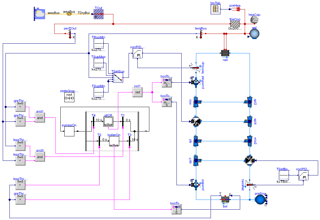
Information
This part of the system model changes the implementation of the control in
Buildings.Examples.Tutorial.Boiler.System6
to use a state machine to switch the pumps and the boiler on and off.
State machines provide an alternate way to implement discrete event,
reactive and hybrid systems.
The state machine that is implemented in this model is shown in
the figure below.
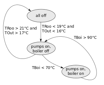
In the figure above, the ovals depict states, and the arrows are transitions between the states.
The transitions fire when the conditions are true.
Implementation
This model was built as follows:
-
First, we copied the model
Buildings.Examples.Tutorial.Boiler.System6
and called it
Buildings.Examples.Tutorial.Boiler.System7.
-
We implemented the state machine using blocks from the library
Modelica.StateGraph.
How to use these blocks is explained in
Modelica.StateGraph.UsersGuide.
The figure below shows the state machine.
The square icons are states, and the black bars
are transitions. The initial state is indicated by the double frame.
The transitions are enabled when their input signal is true.
The numbers to the right of the transition indicate the delay in seconds.
If a delay is present, the input needs to be true during the entire duration of the delay
for a transition to fire. The active state is rendered green.
Some states have a Boolean output signal that is used to switch
components such as the pumps and the boiler on or off.
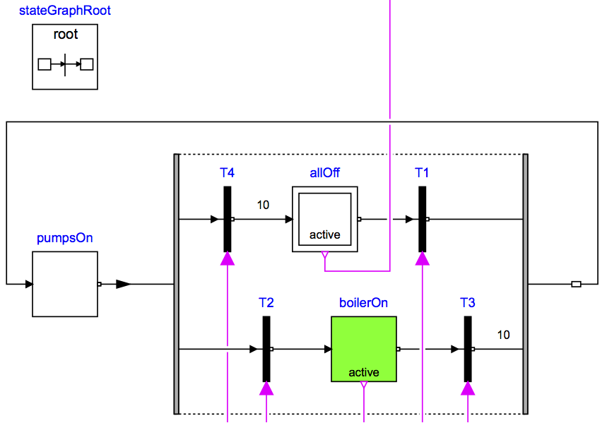
In our implementation, the state allOff is the initial state,
indicated by its double frame.
The transition T1 is used to switch the pumps on.
Once the pumpsOn state is active, there are two alternate
paths. Either transition T2 may fire, which
would switch the boiler on, or T4 may fire, which would return
to the allOff state.
Hence, the boiler can only be on when the pumps are on.
From the state boilerOn, the only next step can be to
transition to the state pumpsOn.
Note that the transitions T3 and T4
only fire when their input is true for the entire duration of 10 seconds.
Hence, the pumps and the boiler must run for at least 10 seconds
before they can be switched off.
When simulating the model
for 2 days, or 172800 seconds, the
response shown below should be seen.
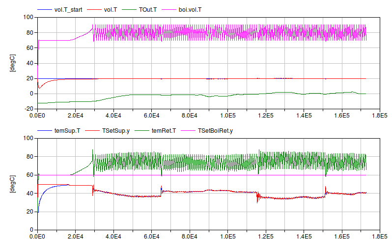

Extends from Modelica.Icons.Example (Icon for runnable examples).
Parameters
| Type | Name | Default | Description |
|---|
| replaceable package MediumA | Buildings.Media.Air | |
| replaceable package MediumW | Buildings.Media.Water | Medium model |
| HeatFlowRate | Q_flow_nominal | 20000 | Nominal heat flow rate of radiator [W] |
| Temperature | TRadSup_nominal | 273.15 + 50 | Radiator nominal supply water temperature [K] |
| Temperature | TRadRet_nominal | 273.15 + 40 | Radiator nominal return water temperature [K] |
| MassFlowRate | mRad_flow_nominal | Q_flow_nominal/4200/(TRadSup... | Radiator nominal mass flow rate [kg/s] |
| Temperature | TBoiSup_nominal | 273.15 + 70 | Boiler nominal supply water temperature [K] |
| Temperature | TBoiRet_min | 273.15 + 60 | Boiler minimum return water temperature [K] |
| MassFlowRate | mBoi_flow_nominal | Q_flow_nominal/4200/(TBoiSup... | Boiler nominal mass flow rate [kg/s] |
| MassFlowRate | mRadVal_flow_nominal | Q_flow_nominal/4200/(TBoiSup... | Radiator nominal mass flow rate [kg/s] |
| Volume | V | 6*10*3 | Room volume [m3] |
| MassFlowRate | mA_flow_nominal | V*1.2*6/3600 | Nominal mass flow rate [kg/s] |
| HeatFlowRate | QRooInt_flow | 4000 | Internal heat gains of the room [W] |
Connectors
| Type | Name | Description |
|---|
| replaceable package MediumA | |
| replaceable package MediumW | Medium model |
| Bus | weaBus | |
Modelica definition
model System7
extends Modelica.Icons.Example;
replaceable package MediumA =
Buildings.Media.Air;
replaceable package MediumW =
Buildings.Media.Water ;
parameter Modelica.SIunits.HeatFlowRate Q_flow_nominal = 20000
;
parameter Modelica.SIunits.Temperature TRadSup_nominal = 273.15+50
;
parameter Modelica.SIunits.Temperature TRadRet_nominal = 273.15+40
;
parameter Modelica.SIunits.MassFlowRate mRad_flow_nominal=
Q_flow_nominal/4200/(TRadSup_nominal-TRadRet_nominal)
;
parameter Modelica.SIunits.Temperature TBoiSup_nominal = 273.15+70
;
parameter Modelica.SIunits.Temperature TBoiRet_min = 273.15+60
;
parameter Modelica.SIunits.MassFlowRate mBoi_flow_nominal=
Q_flow_nominal/4200/(TBoiSup_nominal-TBoiRet_min)
;
parameter Modelica.SIunits.MassFlowRate mRadVal_flow_nominal=
Q_flow_nominal/4200/(TBoiSup_nominal-TRadRet_nominal)
;
Buildings.Fluid.MixingVolumes.MixingVolume vol(
redeclare package Medium =
MediumA,
energyDynamics=Modelica.Fluid.Types.Dynamics.FixedInitial,
m_flow_nominal=mA_flow_nominal,
V=V);
Modelica.Thermal.HeatTransfer.Components.ThermalConductor theCon(G=20000/30)
;
parameter Modelica.SIunits.Volume V=6*10*3 ;
parameter Modelica.SIunits.MassFlowRate mA_flow_nominal = V*1.2*6/3600
;
parameter Modelica.SIunits.HeatFlowRate QRooInt_flow = 4000
;
Modelica.Thermal.HeatTransfer.Sources.PrescribedHeatFlow preHea
;
Modelica.Thermal.HeatTransfer.Components.HeatCapacitor heaCap(C=2*V*1.2*1006)
;
Buildings.Controls.OBC.CDL.Continuous.Sources.TimeTable timTab(
extrapolation=Buildings.Controls.OBC.CDL.Types.Extrapolation.Periodic,
smoothness=Buildings.Controls.OBC.CDL.Types.Smoothness.ConstantSegments,
table=[-6, 0;
8, QRooInt_flow;
18, 0],
timeScale=3600) ;
Buildings.Fluid.HeatExchangers.Radiators.RadiatorEN442_2 rad(
redeclare package Medium =
MediumW,
energyDynamics=Modelica.Fluid.Types.Dynamics.FixedInitial,
Q_flow_nominal=Q_flow_nominal,
T_a_nominal=TRadSup_nominal,
T_b_nominal=TRadRet_nominal) ;
Buildings.Fluid.Sensors.TemperatureTwoPort temSup(
redeclare package Medium =
MediumW,
m_flow_nominal=mRad_flow_nominal) ;
Modelica.Thermal.HeatTransfer.Sensors.TemperatureSensor temRoo
;
Buildings.Fluid.Movers.FlowControlled_m_flow pumRad(
redeclare package Medium =
MediumW,
energyDynamics=Modelica.Fluid.Types.Dynamics.FixedInitial,
m_flow_nominal=mRad_flow_nominal) ;
Buildings.Fluid.FixedResistances.Junction mix(
redeclare package Medium =
MediumW,
energyDynamics=Modelica.Fluid.Types.Dynamics.FixedInitial,
m_flow_nominal={mRadVal_flow_nominal,-mRad_flow_nominal,mRad_flow_nominal
- mRadVal_flow_nominal},
dp_nominal={100,-8000,6750}) ;
Buildings.Fluid.FixedResistances.Junction spl(
redeclare package Medium =
MediumW,
energyDynamics=Modelica.Fluid.Types.Dynamics.FixedInitial,
m_flow_nominal={mBoi_flow_nominal,-mRadVal_flow_nominal,-mBoi_flow_nominal},
dp_nominal={200,-200,-50}) ;
Buildings.Fluid.FixedResistances.Junction spl2(
redeclare package Medium =
MediumW,
energyDynamics=Modelica.Fluid.Types.Dynamics.FixedInitial,
dp_nominal={0,0,0},
m_flow_nominal={mRad_flow_nominal,-mRadVal_flow_nominal,-mRad_flow_nominal
+ mRadVal_flow_nominal});
Buildings.Fluid.FixedResistances.Junction mix2(
redeclare package Medium =
MediumW,
energyDynamics=Modelica.Fluid.Types.Dynamics.FixedInitial,
dp_nominal={0,-200,0},
m_flow_nominal={mRadVal_flow_nominal,-mBoi_flow_nominal,mBoi_flow_nominal})
;
Buildings.Fluid.FixedResistances.Junction spl4(
redeclare package Medium =
MediumW,
energyDynamics=Modelica.Fluid.Types.Dynamics.FixedInitial,
m_flow_nominal=mRadVal_flow_nominal*{1,-1,-1},
dp_nominal=200*{1,-1,-1}) ;
Buildings.Fluid.Movers.FlowControlled_m_flow pumBoi(
redeclare package Medium =
MediumW,
energyDynamics=Modelica.Fluid.Types.Dynamics.FixedInitial,
m_flow_nominal=mBoi_flow_nominal) ;
Buildings.Fluid.Boilers.BoilerPolynomial boi(
redeclare package Medium =
MediumW,
energyDynamics=Modelica.Fluid.Types.Dynamics.FixedInitial,
m_flow_nominal=mBoi_flow_nominal,
dp_nominal=2000,
Q_flow_nominal=Q_flow_nominal,
fue=
Buildings.Fluid.Data.Fuels.HeatingOilLowerHeatingValue()) ;
Buildings.Fluid.Actuators.Valves.ThreeWayEqualPercentageLinear valRad(
redeclare package Medium =
MediumW,
energyDynamics=Modelica.Fluid.Types.Dynamics.FixedInitial,
m_flow_nominal=mRadVal_flow_nominal,
l={0.01,0.01},
dpValve_nominal=6000) ;
Buildings.Fluid.Sources.Boundary_pT preSou(
redeclare package Medium =
MediumW,
nPorts=1)
;
Buildings.Fluid.Actuators.Valves.ThreeWayEqualPercentageLinear valBoi(
redeclare package Medium =
MediumW,
energyDynamics=Modelica.Fluid.Types.Dynamics.FixedInitial,
m_flow_nominal=mBoi_flow_nominal,
l={0.01,0.01},
dpValve_nominal=6000) ;
Buildings.Fluid.Sensors.TemperatureTwoPort temRet(
redeclare package Medium =
MediumW, m_flow_nominal=mBoi_flow_nominal) ;
Buildings.Fluid.FixedResistances.Junction spl1(
redeclare package Medium =
MediumW,
energyDynamics=Modelica.Fluid.Types.Dynamics.FixedInitial,
m_flow_nominal={mBoi_flow_nominal,-mBoi_flow_nominal,-mBoi_flow_nominal},
dp_nominal={0,0,-200}) ;
Modelica.Thermal.HeatTransfer.Sensors.TemperatureSensor senTOut
;
Buildings.Controls.OBC.CDL.Conversions.BooleanToReal booToReaRad1(realTrue=mBoi_flow_nominal)
;
Buildings.Controls.OBC.CDL.Conversions.BooleanToReal booToReaRad2(realTrue=1)
;
Buildings.Controls.OBC.CDL.Conversions.BooleanToReal booToReaRad(realTrue=mRad_flow_nominal)
;
Buildings.Controls.OBC.CDL.Continuous.Sources.Constant TSetBoiRet(k=TBoiRet_min)
;
Buildings.Controls.OBC.CDL.Continuous.PID conPIDBoi(
Td=1,
controllerType=Buildings.Controls.OBC.CDL.Types.SimpleController.PI,
k=0.1,
Ti=120,
reverseActing=false) ;
Buildings.Controls.OBC.CDL.Continuous.PID conPIDRad(
Td=1,
controllerType=Buildings.Controls.OBC.CDL.Types.SimpleController.PI,
k=0.1,
Ti=120) ;
Buildings.Controls.OBC.CDL.Continuous.Line TSetSup
;
Buildings.Controls.OBC.CDL.Continuous.Sources.Constant TSupMin(k=273.15 + 21)
;
Buildings.Controls.OBC.CDL.Continuous.Sources.Constant TSupMax(k=273.15 + 50)
;
Buildings.Controls.OBC.CDL.Continuous.Sources.Constant TRooMin(k=273.15 + 19)
;
BoundaryConditions.WeatherData.ReaderTMY3 weaDat(
filNam=
Modelica.Utilities.Files.loadResource("modelica://Buildings/Resources/weatherdata/USA_IL_Chicago-OHare.Intl.AP.725300_TMY3.mos"))
;
BoundaryConditions.WeatherData.Bus weaBus;
Modelica.Thermal.HeatTransfer.Sources.PrescribedTemperature TOut
;
inner Modelica.StateGraph.StateGraphRoot stateGraphRoot
;
Modelica.StateGraph.Alternative alternative
;
Modelica.StateGraph.InitialStepWithSignal allOff(
nOut=1,
nIn=1) ;
Modelica.StateGraph.TransitionWithSignal T1 ;
Modelica.StateGraph.StepWithSignal boilerOn(
nIn=1,
nOut=1) ;
Modelica.StateGraph.TransitionWithSignal T2 ;
Buildings.Controls.OBC.CDL.Continuous.GreaterThreshold greThrBoi(t=273.15 +
90) ;
Modelica.StateGraph.TransitionWithSignal T3(
waitTime=10, enableTimer=true) ;
Modelica.StateGraph.TransitionWithSignal T4(
waitTime=10, enableTimer=true) ;
Modelica.StateGraph.Step pumpsOn(nIn=1, nOut=1) ;
Buildings.Controls.OBC.CDL.Continuous.LessThreshold lessThreshold(t=273.15 +
19);
Buildings.Controls.OBC.CDL.Continuous.LessThreshold lessThreshold1(t=273.15
+ 16);
Buildings.Controls.OBC.CDL.Logical.And and3;
Buildings.Controls.OBC.CDL.Continuous.LessThreshold lessThreshold2(t=273.15
+ 70) ;
Buildings.Controls.OBC.CDL.Continuous.GreaterThreshold greThrTRoo(t=273.15 +
21) ;
Buildings.Controls.OBC.CDL.Continuous.GreaterThreshold greThrTROut(t=273.15
+ 17) ;
Buildings.Controls.OBC.CDL.Logical.And and1;
Buildings.Controls.OBC.CDL.Logical.Not not1 ;
equation
connect(theCon.port_b, vol.heatPort);
connect(preHea.port, vol.heatPort);
connect(heaCap.port, vol.heatPort);
connect(timTab.y[1], preHea.Q_flow);
connect(temSup.port_b, rad.port_a);
connect(temRoo.port, vol.heatPort);
connect(rad.heatPortCon, vol.heatPort);
connect(rad.heatPortRad, vol.heatPort);
connect(pumRad.port_b, temSup.port_a);
connect(boi.port_b, pumBoi.port_a);
connect(pumBoi.port_b, spl1.port_1);
connect(spl1.port_2, spl.port_1);
connect(spl.port_2, valRad.port_1);
connect(valRad.port_2, mix.port_1);
connect(spl1.port_3, valBoi.port_3);
connect(valBoi.port_2, temRet.port_a);
connect(temRet.port_b, boi.port_a);
connect(boi.port_a, preSou.ports[1]);
connect(mix2.port_2, valBoi.port_1);
connect(spl4.port_2, mix2.port_1);
connect(spl2.port_2, spl4.port_1);
connect(valRad.port_3, spl4.port_3);
connect(spl.port_3, mix2.port_3);
connect(mix.port_3, spl2.port_3);
connect(mix.port_2, pumRad.port_a);
connect(rad.port_b, spl2.port_1);
connect(booToReaRad2.y, boi.y);
connect(temSup.T, conPIDRad.u_m);
connect(weaDat.weaBus, weaBus);
connect(weaBus.TDryBul, TOut.T);
connect(TOut.port, theCon.port_a);
connect(TOut.port, senTOut.port);
connect(allOff.outPort[1], T1.inPort);
connect(temRoo.T, lessThreshold.u);
connect(lessThreshold1.u, senTOut.T);
connect(lessThreshold.y, and3.u1);
connect(lessThreshold1.y, and3.u2);
connect(boi.T, lessThreshold2.u);
connect(T2.outPort, boilerOn.inPort[1]);
connect(boi.T, greThrBoi.u);
connect(boilerOn.outPort[1], T3.inPort);
connect(temRoo.T, greThrTRoo.u);
connect(senTOut.T, greThrTROut.u);
connect(greThrTRoo.y, and1.u1);
connect(greThrTROut.y, and1.u2);
connect(not1.y, booToReaRad.u);
connect(not1.y, booToReaRad1.u);
connect(T4.outPort, allOff.inPort[1]);
connect(conPIDRad.y, valRad.y);
connect(booToReaRad.y, pumRad.m_flow_in);
connect(conPIDBoi.y, valBoi.y);
connect(booToReaRad1.y, pumBoi.m_flow_in);
connect(TSetBoiRet.y, conPIDBoi.u_s);
connect(temRet.T, conPIDBoi.u_m);
connect(T1.condition, and3.y);
connect(booToReaRad2.u, boilerOn.active);
connect(lessThreshold2.y, T2.condition);
connect(T4.condition, and1.y);
connect(T3.condition, greThrBoi.y);
connect(allOff.active, not1.u);
connect(pumpsOn.outPort[1], alternative.inPort);
connect(alternative.outPort, pumpsOn.inPort[1]);
connect(T4.inPort, alternative.split[1]);
connect(T2.inPort, alternative.split[2]);
connect(T1.outPort, alternative.join[1]);
connect(T3.outPort, alternative.join[2]);
connect(TSetSup.x1,TRooMin. y);
connect(TSupMax.y,TSetSup. f1);
connect(TSupMin.y,TSetSup. f2);
connect(TSupMin.y,TSetSup. x2);
connect(TSetSup.u, temRoo.T);
connect(conPIDRad.u_s,TSetSup. y);
end System7;
 Buildings.Examples.Tutorial.Boiler.System1