Buildings.Examples.ChillerPlant.BaseClasses.Controls
Package with control components for Buildings.Examples.ChillerPlant
Information
This package contains component models that are used to construct the control system in Buildings.Examples.ChillerPlant.
Extends from Modelica.Icons.VariantsPackage (Icon for package containing variants).
Package Content
| Name | Description |
|---|---|
| Controller for battery | |
| Control unit for enabling/disabling chiller | |
| Output y=k-u | |
| A two-pieces linear piecewise function | |
| Count the number of actuators that have request | |
| Trim and respond logic | |
| Trim and respond logic | |
| Control unit for WSE | |
| Test of components |
 Buildings.Examples.ChillerPlant.BaseClasses.Controls.BatteryControl
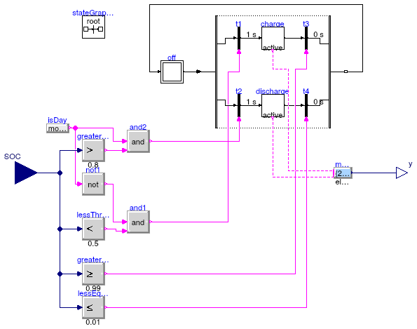
Controller for battery
Information
Block for a battery controller. The battery is charged during night if its charge is below a threshold. It remains charging until it is full. During day, it discharges provided that its charge is above a threshold. It remains discharging until it is empty.
Connectors
| Type | Name | Description |
|---|---|---|
| input RealInput | SOC | State of charge |
| output RealOutput | y | Power charged or discharged from battery |
Modelica definition
 Buildings.Examples.ChillerPlant.BaseClasses.Controls.ChillerSwitch
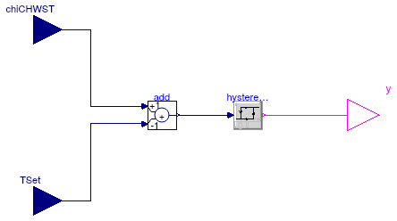
Control unit for enabling/disabling chiller
Information
The controls for enabling/disabling chiller are as follows:-
The chiller is enabled when
TChi_CHWST > TChiSet + TDeaBan
-
The chiller is disabled when
TChi_CHWST ≤ TChiSet
Extends from Modelica.Blocks.Icons.Block (Basic graphical layout of input/output block).
Parameters
| Type | Name | Default | Description |
|---|---|---|---|
| Temperature | deaBan | Dead band of temperature to prevent chiller short cycling [K] |
Connectors
| Type | Name | Description |
|---|---|---|
| input RealInput | chiCHWST | Chiller chilled water supply temperature (water entering chiller) [K] |
| output BooleanOutput | y | Control signal for chiller. 1: Enable, 0: Disable |
| input RealInput | TSet | Set temperature of chiller [K] |
Modelica definition
 Buildings.Examples.ChillerPlant.BaseClasses.Controls.KMinusU
Output y=k-u

Information
This component computes the value ofy = k - u.
Extends from Modelica.Blocks.Icons.Block (Basic graphical layout of input/output block).
Parameters
| Type | Name | Default | Description |
|---|---|---|---|
| Real | k | Sum of u and y |
Connectors
| Type | Name | Description |
|---|---|---|
| input RealInput | u | Input |
| output RealOutput | y | Output |
Modelica definition
 Buildings.Examples.ChillerPlant.BaseClasses.Controls.LinearPiecewiseTwo
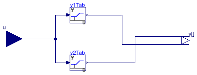
A two-pieces linear piecewise function
Information
This component calcuates the output according to two piecewise linear function as
| x0 ≤ u ≤ x1: | y1 = y10 + u (y11-y10)/(x1-x0) y2 = y20 |
| x1 < u ≤ x2: | y1 = y11 y2 = y20 + (u-x1) (y21-y20)/(x2-x1) |
Extends from Modelica.Blocks.Icons.Block (Basic graphical layout of input/output block).
Parameters
| Type | Name | Default | Description |
|---|---|---|---|
| Real | x0 | First interval [x0, x1] | |
| Real | x1 | First interval [x0, x1] and second interval (x1, x2] | |
| Real | x2 | Second interval (x1, x2] | |
| Real | y10 | y[1] at u = x0 | |
| Real | y11 | y[1] at u = x1 | |
| Real | y20 | y[2] at u = x1 | |
| Real | y21 | y[2] at u = x2 |
Connectors
| Type | Name | Description |
|---|---|---|
| input RealInput | u | Set point |
| output RealOutput | y[2] | Connectors of Real output signal |
Modelica definition
 Buildings.Examples.ChillerPlant.BaseClasses.Controls.RequestCounter
Count the number of actuators that have request

Information
This model counts the number of requests sent by actuators. A request is triggerred when an input singaluAct[i] is larger than uTri.
Extends from Modelica.Blocks.Icons.Block (Basic graphical layout of input/output block).
Parameters
| Type | Name | Default | Description |
|---|---|---|---|
| Integer | nAct | Number of actuators | |
| Real | uTri | Value to trigger a request from actuator |
Connectors
| Type | Name | Description |
|---|---|---|
| output IntegerOutput | nInc | Number of actuators requesting control signal increase |
| input RealInput | uAct[nAct] | Input signal from actuators |
Modelica definition
 Buildings.Examples.ChillerPlant.BaseClasses.Controls.TrimAndRespond
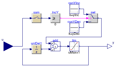
Trim and respond logic
Information
This model implements the trim and respond logic. The model samples the outputs of actuators every tSam.
The control sequence is as follows:
- If
u ≥ 0, theny = y + nActInc, - If
u < 0, theny = y - yDec.
Extends from Modelica.Blocks.Interfaces.DiscreteSISO (Single Input Single Output discrete control block).
Parameters
| Type | Name | Default | Description |
|---|---|---|---|
| Time | samplePeriod | Sample period of component [s] | |
| Time | startTime | 0 | First sample time instant [s] |
| Real | uTri | Value to triggering the request for actuator | |
| Real | yEqu0 | y setpoint when equipment starts | |
| Real | yDec | y decrement (must be negative) | |
| Real | yInc | y increment (must be positive) |
Connectors
| Type | Name | Description |
|---|---|---|
| input RealInput | u | Connector of Real input signal |
| output RealOutput | y | Connector of Real output signal |
Modelica definition
 Buildings.Examples.ChillerPlant.BaseClasses.Controls.TrimAndRespondContinuousTimeApproximation
Trim and respond logic
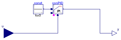
Information
This model implements a continuous time approximation to the trim and respond control algorithm.
Extends from Modelica.Blocks.Interfaces.SISO (Single Input Single Output continuous control block).
Connectors
| Type | Name | Description |
|---|---|---|
| input RealInput | u | Connector of Real input signal |
| output RealOutput | y | Connector of Real output signal |
Modelica definition
 Buildings.Examples.ChillerPlant.BaseClasses.Controls.WSEControl
Control unit for WSE
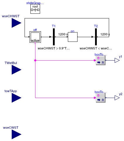
Information
This component decides if the WSE is set to on or off. The WSE is enabled when
- The WSE has been disabled for at least 20 minutes, and
- TWSE_CHWST > 0.9 TWetBul + TTowApp + TWSEApp
The WSE is disabled when
- The WSE has been enabled for at least 20 minutes, and
- TWSE_CHWRT < 1 + TWSE_CWST
where TWSE_CHWST is the chilled water supply temperature for the WSE, TWetBul is the wet bulb temperature, TTowApp is the cooling tower approach, TWSEApp is the approach for the WSE, TWSE_CHWRT is the chilled water return temperature for the WSE, and TWSE_CWST is the condenser water return temperature for the WSE.
Parameters
| Type | Name | Default | Description |
|---|---|---|---|
| TemperatureDifference | dTOff | 1 | Temperature difference to switch WSE off [K] |
| TemperatureDifference | dTW | 1 | Temperature difference that is added to WSE on guard [K] |
Connectors
| Type | Name | Description |
|---|---|---|
| input RealInput | wseCHWST | WSE chilled water supply temperature (water entering WSE) [K] |
| output RealOutput | y2 | Control signal for chiller shutoff valve |
| input RealInput | TWetBul | Wet bulb temperature [K] |
| input RealInput | towTApp | Cooling tower approach [K] |
| input RealInput | wseCWST | WSE condenser water supply temperature (water entering WSE) [K] |
| output RealOutput | y1 | Control signal for WSE shutoff valve |
Modelica definition
 Buildings.Examples.ChillerPlant.BaseClasses.Controls.TrimAndRespond.Sampler
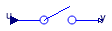
Information
Extends from Modelica.Blocks.Discrete.Sampler (Ideal sampling of continuous signals).
Parameters
| Type | Name | Default | Description |
|---|---|---|---|
| Time | samplePeriod | Sample period of component [s] | |
| Time | startTime | 0 | First sample time instant [s] |
Connectors
| Type | Name | Description |
|---|---|---|
| input RealInput | u | Connector of Real input signal |
| output RealOutput | y | Connector of Real output signal |
Modelica definition
 Buildings.Examples.ChillerPlant.BaseClasses.Controls.TrimAndRespond.UnitDelay
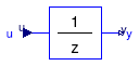
Information
Extends from Modelica.Blocks.Discrete.UnitDelay (Unit Delay Block).
Parameters
| Type | Name | Default | Description |
|---|---|---|---|
| Real | y_start | 0 | Initial value of output signal |
| Time | samplePeriod | Sample period of component [s] | |
| Time | startTime | 0 | First sample time instant [s] |
Connectors
| Type | Name | Description |
|---|---|---|
| input RealInput | u | Connector of Real input signal |
| output RealOutput | y | Connector of Real output signal |