Buildings.Electrical.DC.Loads.Examples

Package with example models

Information

This package contains examples for the use of models that can be found in Buildings.Electrical.DC.Loads.

Extends from Modelica.Icons.ExamplesPackage (Icon for packages containing runnable examples).

Package Content

Name Description
Buildings.Electrical.DC.Loads.Examples.LinearizedLoad LinearizedLoad Example model to check the linearized load model
Buildings.Electrical.DC.Loads.Examples.Resistor Resistor Example model for resistor
Buildings.Electrical.DC.Loads.Examples.VariableLoad VariableLoad Example using variable loads models

Buildings.Electrical.DC.Loads.Examples.LinearizedLoad Buildings.Electrical.DC.Loads.Examples.LinearizedLoad

Example model to check the linearized load model

Buildings.Electrical.DC.Loads.Examples.LinearizedLoad

Information

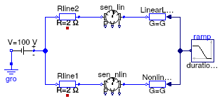
This example demonstrates the use of a linealized load model Buildings.Electrical.DC.Loads.Conductor.

Both loads are connected to the same DC voltage source through a resistive element that represents a line. The loads consume the same amount of power that is specified by the input ramp signal.

The nonlinear conductor model NonlinearLoad consumes exactly the amount of power specified by the input NonlinearLoad.Pow.

The linearized conductor model LinearizedLoad does not consumes the amount of power specified by the input LinearizedLoad.Pow. The voltage at the load deviates from the nominal value when the power consumption increases. Since the model is approximated in a neighbor of the nominal voltage, moving from that point introduces approximation errors. The plot below shows the error introduced with such an approximation.

image

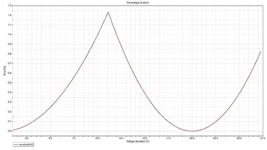
The linearized load is tested over a voltage variation of about 30 % of the nominal voltage and within this range the maximum error is 1.23457 % that occurs when the voltage deviation is 11.11 %.

Extends from Modelica.Icons.Example (Icon for runnable examples).

Modelica definition

model LinearizedLoad "Example model to check the linearized load model" extends Modelica.Icons.Example; Real error = (sen_nlin.P - sen_lin.P)*100/sen_nlin.P "Percentage of error between the linearized and actual power consumption"; Real deltaV = LinearLoad.V_nominal - sen_lin.V "Voltage distance between nominal condition and actual voltage"; Buildings.Electrical.DC.Loads.Conductor NonlinearLoad( linearized=false, mode=Buildings.Electrical.Types.Load.VariableZ_P_input, V_nominal=100, P_nominal=0) "Nonlinear load model"; Sources.ConstantVoltage sou(V=100) "Voltage source"; Modelica.Electrical.Analog.Basic.Ground gro "Ground"; Lines.TwoPortResistance Rline1(R=2) "Line resistance"; Sensors.GeneralizedSensor sen_nlin "Sensor"; Buildings.Electrical.DC.Loads.Conductor LinearLoad( mode=Buildings.Electrical.Types.Load.VariableZ_P_input, V_nominal=100, linearized=true, P_nominal=0) "Linearized load model"; Sensors.GeneralizedSensor sen_lin "Sensor"; Lines.TwoPortResistance Rline2(R=2) "Line resistance"; Modelica.Blocks.Sources.Ramp ramp( duration=0.5, startTime=0.2, offset=-50, height=-950) "Power consumption"; equation connect(sou.terminal, Rline1.terminal_n); connect(Rline1.terminal_p, sen_nlin.terminal_n); connect(sen_nlin.terminal_p, NonlinearLoad.terminal); connect(LinearLoad.terminal, sen_lin.terminal_p); connect(sou.n, gro.p); connect(sou.terminal, Rline2.terminal_n); connect(Rline2.terminal_p, sen_lin.terminal_n); connect(LinearLoad.Pow, ramp.y); connect(NonlinearLoad.Pow, ramp.y); end LinearizedLoad;

Buildings.Electrical.DC.Loads.Examples.Resistor Buildings.Electrical.DC.Loads.Examples.Resistor

Example model for resistor

Buildings.Electrical.DC.Loads.Examples.Resistor

Information

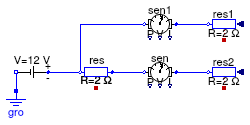
This example demonstrates the use of the resistor model.

Extends from Modelica.Icons.Example (Icon for runnable examples).

Modelica definition

model Resistor "Example model for resistor" extends Modelica.Icons.Example; Buildings.Electrical.DC.Loads.Resistor res2(R=2, V_nominal=12) "Resistor"; Sources.ConstantVoltage sou(V=12) "Voltage source"; Modelica.Electrical.Analog.Basic.Ground gro "Ground"; Lines.TwoPortResistance res(R=2) "Line resistance"; Sensors.GeneralizedSensor sen "Sensor"; Buildings.Electrical.DC.Loads.Resistor res1(R=2, V_nominal=12) "Resistor"; Sensors.GeneralizedSensor sen1 "Sensor"; equation connect(sou.terminal, res.terminal_n); connect(res.terminal_p, sen.terminal_n); connect(sen.terminal_p,res2. terminal); connect(res1.terminal, sen1.terminal_p); connect(sen1.terminal_n, res.terminal_n); connect(sou.n, gro.p); end Resistor;

Buildings.Electrical.DC.Loads.Examples.VariableLoad Buildings.Electrical.DC.Loads.Examples.VariableLoad

Example using variable loads models

Buildings.Electrical.DC.Loads.Examples.VariableLoad

Information

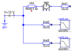
This example shows how to use three different types of load models. Each load is of type Buildings.Electrical.DC.Loads.Conductor.

The first load loa1consumes a constant amount of power. The second and the third loads (loa2 and loa3) consume a variable amount of power. The load loa2 has a variable input y between 0 and 1 that specifies the portion of nominal power that is consumed. The load loa3 has a variable input Pow that represents the actual power consumed (or produced) by the load.

Extends from Modelica.Icons.Example (Icon for runnable examples).

Modelica definition

model VariableLoad "Example using variable loads models" extends Modelica.Icons.Example; Conductor loa1( V_nominal=12, linearized=false, P_nominal=-50) "Load"; Sources.ConstantVoltage sou(V=12) "Voltage source"; Modelica.Electrical.Analog.Basic.Ground gro "Ground"; Conductor loa2( mode=Types.Load.VariableZ_y_input, V_nominal=12, P_nominal=-50) "Load"; Modelica.Blocks.Sources.Ramp varLoad_y( height=0.8, duration=0.5, startTime=0.3, offset=0) "Power signal"; Conductor loa3( V_nominal=12, P_nominal=0, mode=Buildings.Electrical.Types.Load.VariableZ_P_input) "Load"; Modelica.Blocks.Sources.Ramp varLoad_P( duration=0.5, startTime=0.3, height=120, offset=-20) "Power signal"; Lines.TwoPortResistance res(R=0.1) "Line resistance"; Sensors.GeneralizedSensor sen "Sensor"; equation connect(sou.terminal, loa2.terminal); connect(varLoad_y.y, loa2.y); connect(sou.terminal, loa3.terminal); connect(varLoad_P.y, loa3.Pow); connect(sou.terminal, res.terminal_n); connect(res.terminal_p, sen.terminal_n); connect(sen.terminal_p, loa1.terminal); connect(sou.n, gro.p); end VariableLoad;