Buildings.Controls.OBC.CDL.Logical
Package with logical blocks
Information
Package with blocks for elementary mathematical functions for boolean variables.
Package Content
| Name | Description |
|---|---|
| Logical 'and': y = u1 and u2 | |
| Logical 'and3': y = u1 and u2 and u3 | |
| Output y is true, if the input u has a rising or falling edge (y = change(u)) | |
| Output y is true, if the input u has a rising edge (y = edge(u)) | |
| Output y is true, if the input u has a falling edge (y = edge(not u)) | |
| Switch between two integer signals | |
| Maintains a true signal until change condition | |
| Switch between two boolean signals | |
| Logical MultiAnd, y = u[1] and u[2] and u[3] and ... | |
| Logical MultiOr, y = u[1] or u[2] or u[3] or ... | |
| Logical 'nand': y = not (u1 and u2) | |
| Logical 'nor': y = not (u1 or u2) | |
| Logical not | |
| On-off controller | |
| Logical 'or': y = u1 or u2 | |
| Logical 'or': y = u1 or u2 or u3 | |
| Breaks algebraic loops by an infinitesimal small time delay (y = pre(u): event iteration continues until u = pre(u)) | |
| Switch between two Real signals | |
| Timer measuring the time from the time instant where the Boolean input became true | |
| Toggles output value whenever its input turns true | |
| Triggered trapezoid generator | |
| Delay a rising edge of the input, but do not delay a falling edge. | |
| Block that holds an output signal for at least a specified duration | |
| Block that holds a true signal for at least a requested duration | |
| Logical 'xor': y = u1 xor u2 | |
| Trigger zero crossing of input u | |
| Package with blocks that generate source signals | |
| Collection of models that validate the logical blocks of the CDL |
 Buildings.Controls.OBC.CDL.Logical.And
Logical 'and': y = u1 and u2

Information
Block that outputs true if all inputs are true.
Otherwise the output is false.
Connectors
| Type | Name | Description |
|---|---|---|
| input BooleanInput | u1 | Connector of first Boolean input signal |
| input BooleanInput | u2 | Connector of second Boolean input signal |
| output BooleanOutput | y | Connector of Boolean output signal |
Modelica definition
 Buildings.Controls.OBC.CDL.Logical.And3
Logical 'and3': y = u1 and u2 and u3
Information
Block that outputs true if all inputs are true.
Otherwise the output is false.
Connectors
| Type | Name | Description |
|---|---|---|
| input BooleanInput | u1 | Connector of first Boolean input signal |
| input BooleanInput | u2 | Connector of second Boolean input signal |
| input BooleanInput | u3 | Connector of second Boolean input signal |
| output BooleanOutput | y | Connector of Boolean output signal |
Modelica definition
 Buildings.Controls.OBC.CDL.Logical.Change
Output y is true, if the input u has a rising or falling edge (y = change(u))

Information
Block that outputs true if the Boolean input has either a rising edge
from false to true or a falling edge from
true to false.
Otherwise the output is false.
Parameters
| Type | Name | Default | Description |
|---|---|---|---|
| Boolean | pre_u_start | false | Start value of pre(u) at initial time |
Connectors
| Type | Name | Description |
|---|---|---|
| input BooleanInput | u | Connector of Boolean input signal |
| output BooleanOutput | y | Connector of Boolean output signal |
Modelica definition
Buildings.Controls.OBC.CDL.Logical.Edge
Output y is true, if the input u has a rising edge (y = edge(u))
Information
Block that outputs true if the Boolean input has a rising edge
from false to true.
Otherwise the output is false.
Parameters
| Type | Name | Default | Description |
|---|---|---|---|
| Boolean | pre_u_start | false | Start value of pre(u) at initial time |
Connectors
| Type | Name | Description |
|---|---|---|
| input BooleanInput | u | Connector of Boolean input signal |
| output BooleanOutput | y | Connector of Boolean output signal |
Modelica definition
Buildings.Controls.OBC.CDL.Logical.FallingEdge
Output y is true, if the input u has a falling edge (y = edge(not u))
Information
Block that outputs true if the Boolean input has a falling edge
from true to false.
Otherwise the output is false.
Parameters
| Type | Name | Default | Description |
|---|---|---|---|
| Boolean | pre_u_start | false | Start value of pre(u) at initial time |
Connectors
| Type | Name | Description |
|---|---|---|
| input BooleanInput | u | Connector of Boolean input signal |
| output BooleanOutput | y | Connector of Boolean output signal |
Modelica definition
 Buildings.Controls.OBC.CDL.Logical.IntegerSwitch
Switch between two integer signals
Information
Block that outputs one of two integer input signals based on a boolean input signal.
If the input signal u2 is true,
the block outputs y = u1.
Otherwise, it outputs y = u3.
Connectors
| Type | Name | Description |
|---|---|---|
| input IntegerInput | u1 | Integer input signal |
| input BooleanInput | u2 | Boolean switch input signal, if true, y=u1, else y=u3 |
| input IntegerInput | u3 | Integer input signal |
| output IntegerOutput | y | Integer output signal |
Modelica definition
 Buildings.Controls.OBC.CDL.Logical.Latch
Maintains a true signal until change condition

Information
Block that generates a true output when the latch input u
rises from false to true, provided that the clear input
clr is false or also became at the same time false.
The output remains true until the clear input clr rises
from false to true.
If the clear input clr is true, the output y
switches to false (if it was true) and it remains false,
regardless of the value of the latch input u.
At initial time, if clr = false, then the output will be
y = pre_y_start. Otherwise it will be y=false
(because the clear input clr is true).
Parameters
| Type | Name | Default | Description |
|---|---|---|---|
| Boolean | pre_y_start | false | Start value of pre(y) if clr=false |
Connectors
| Type | Name | Description |
|---|---|---|
| input BooleanInput | u | Latch input |
| input BooleanInput | clr | Clear input |
| output BooleanOutput | y | Output signal |
Modelica definition
 Buildings.Controls.OBC.CDL.Logical.LogicalSwitch
Switch between two boolean signals

Information
Block that outputs one of two boolean input signals based on a boolean input signal.
If the input signal u2 is true,
the block outputs y = u1.
Otherwise, it outputs y = u3.
Connectors
| Type | Name | Description |
|---|---|---|
| input BooleanInput | u1 | Boolean input signal |
| input BooleanInput | u2 | Boolean switch input signal, if true, y=u1, else y=u3 |
| input BooleanInput | u3 | Boolean input signal |
| output BooleanOutput | y | Booelan output signal |
Modelica definition
 Buildings.Controls.OBC.CDL.Logical.MultiAnd
Logical MultiAnd, y = u[1] and u[2] and u[3] and ...
Information
Block that outputs y = true if and only if
all elements of the input vector u are true.
If no connection to the input connector u is present,
the output is y=false.
See Buildings.Controls.OBC.CDL.Logical.Validation.MultiAnd for an example.
Connectors
| Type | Name | Description |
|---|---|---|
| input BooleanInput | u[nu] | Connector of Boolean input signals |
| output BooleanOutput | y | Connector of Boolean output signal |
Modelica definition
Buildings.Controls.OBC.CDL.Logical.MultiOr
Logical MultiOr, y = u[1] or u[2] or u[3] or ...
Information
Block that outputs y = true if any element in the input
vector u is true.
If no connection to the input connector u is present,
the output is y=false.
See Buildings.Controls.OBC.CDL.Logical.Validation.MultiOr for an example.
Connectors
| Type | Name | Description |
|---|---|---|
| input BooleanInput | u[nu] | Connector of Boolean input signals |
| output BooleanOutput | y | Connector of Boolean output signal |
Modelica definition
 Buildings.Controls.OBC.CDL.Logical.Nand
Logical 'nand': y = not (u1 and u2)
Information
Block that outputs true if at least
one input is false.
Otherwise the output is false.
Connectors
| Type | Name | Description |
|---|---|---|
| input BooleanInput | u1 | Connector of first Boolean input signal |
| input BooleanInput | u2 | Connector of second Boolean input signal |
| output BooleanOutput | y | Connector of Boolean output signal |
Modelica definition
Buildings.Controls.OBC.CDL.Logical.Nor
Logical 'nor': y = not (u1 or u2)
Information
Block that outputs true if none of the inputs is true.
Otherwise the output is false.
Connectors
| Type | Name | Description |
|---|---|---|
| input BooleanInput | u1 | Connector of first Boolean input signal |
| input BooleanInput | u2 | Connector of second Boolean input signal |
| output BooleanOutput | y | Connector of Boolean output signal |
Modelica definition
 Buildings.Controls.OBC.CDL.Logical.Not
Logical not

Information
Block that outputs true if the input is false,
and false if the input is true.
Connectors
| Type | Name | Description |
|---|---|---|
| input BooleanInput | u | Connector of Boolean input signal |
| output BooleanOutput | y | Connector of Boolean output signal |
Modelica definition
 Buildings.Controls.OBC.CDL.Logical.OnOffController
On-off controller
Information
Block that represents and on/off controller.
The block outputs true when
the input signal u falls below
the reference signal minus half of the bandwidth.
It sets the output signal to false when the input
signal u exceeds the reference signal
plus half of the bandwidth.
The parameter pre_y_start is used to initialize the
previous value of the output pre(y).
Parameters
| Type | Name | Default | Description |
|---|---|---|---|
| Real | bandwidth | Bandwidth around reference signal | |
| Boolean | pre_y_start | false | Value of pre(y) at initial time |
Connectors
| Type | Name | Description |
|---|---|---|
| input RealInput | reference | Connector of Real input signal used as reference signal |
| input RealInput | u | Connector of Real input signal used as measurement signal |
| output BooleanOutput | y | Connector of Real output signal used as actuator signal |
Modelica definition
 Buildings.Controls.OBC.CDL.Logical.Or
Logical 'or': y = u1 or u2

Information
Block that outputs true if at least one input
is true.
Otherwise the output is false.
Connectors
| Type | Name | Description |
|---|---|---|
| input BooleanInput | u1 | Connector of first Boolean input signal |
| input BooleanInput | u2 | Connector of second Boolean input signal |
| output BooleanOutput | y | Connector of Boolean output signal |
Modelica definition
 Buildings.Controls.OBC.CDL.Logical.Or3
Logical 'or': y = u1 or u2 or u3

Information
Block that outputs true if at least one input
is true.
Otherwise the output is false.
Connectors
| Type | Name | Description |
|---|---|---|
| input BooleanInput | u1 | Connector of first Boolean input signal |
| input BooleanInput | u2 | Connector of second Boolean input signal |
| input BooleanInput | u3 | Connector of second Boolean input signal |
| output BooleanOutput | y | Connector of Boolean output signal |
Modelica definition
 Buildings.Controls.OBC.CDL.Logical.Pre
Breaks algebraic loops by an infinitesimal small time delay (y = pre(u): event iteration continues until u = pre(u))

Information
This block delays the Boolean input by an infinitesimal small time delay and therefore breaks algebraic loops. In a network of logical blocks, in every closed connection loop, at least one logical block must have a delay, since algebraic systems of Boolean equations are not solvable.
This block returns the value of the input signal u from the
last event iteration. The event iteration stops once both
values are identical, i.e., if u = pre(u).
Parameters
| Type | Name | Default | Description |
|---|---|---|---|
| Boolean | pre_u_start | false | Start value of pre(u) at initial time |
Connectors
| Type | Name | Description |
|---|---|---|
| input BooleanInput | u | Connector of Boolean input signal |
| output BooleanOutput | y | Connector of Boolean output signal |
Modelica definition
 Buildings.Controls.OBC.CDL.Logical.Switch
Switch between two Real signals
Information
Block that outputs one of two real input signals based on a boolean input signal.
If the input signal u2 is true,
the block outputs y = u1.
Otherwise, it outputs y = u3.
Connectors
| Type | Name | Description |
|---|---|---|
| input RealInput | u1 | Real input signal |
| input BooleanInput | u2 | Boolean switch input signal, if true, y=u1, else y=u3 |
| input RealInput | u3 | Real input signal |
| output RealOutput | y | Real output signal |
Modelica definition
 Buildings.Controls.OBC.CDL.Logical.Timer
Timer measuring the time from the time instant where the Boolean input became true
Information
Timer with option to accumulate time until it is reset by an input signal.
Each time the Boolean input u becomes true, the timer runs, otherwise
it is dormant.
If the parameter accumulate is false, the timer is set to zero each time the
input u becomes false.
If accumulate = true, an input reset is enabled, the timer accumulates time,
and the timer is set to zero only when the value of the input reset becomes true.
Parameters
| Type | Name | Default | Description |
|---|---|---|---|
| Boolean | accumulate | false | If true, accumulate time until Boolean input 'reset' becomes true, otherwise reset timer whenever u becomes true |
Connectors
| Type | Name | Description |
|---|---|---|
| input BooleanInput | u | Connector for signal that switches timer on if true, and off if false |
| input BooleanInput | reset | Connector for signal that sets timer to zero if it switches to true |
| output RealOutput | y | Timer output [s] |
Modelica definition
 Buildings.Controls.OBC.CDL.Logical.Toggle
Toggles output value whenever its input turns true
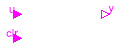
Information
Block that generates a true output when toggle input u
rises from false to true, provided that the clear input
clr is false or also became at the same time
false. The output remains true until
-
the toggle input
urises fromfalsetotrueagain, or -
the clear input
clrrises fromfalsetotrue.
If the clear input clr is true, the output y
switches to false (if it was true) and it remains false,
regardless of the value of the toggle input u.
At initial time, if clr = false, then the output will be
y = pre_y_start. Otherwise it will be y=false
(because the clear input clr is true).
Parameters
| Type | Name | Default | Description |
|---|---|---|---|
| Boolean | pre_y_start | false | Start value of pre(y) if clr=false |
Connectors
| Type | Name | Description |
|---|---|---|
| input BooleanInput | u | Toggle input |
| input BooleanInput | clr | Clear input |
| output BooleanOutput | y | Output signal |
Modelica definition
 Buildings.Controls.OBC.CDL.Logical.TriggeredTrapezoid
Triggered trapezoid generator
Information
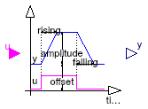
Block that represents a triggered trapezoid.
The block has a Boolean input and a Real
output signal and requires the parameters amplitude,
rising, falling and offset. The
output signal y represents a trapezoidal signal dependent on the
input signal u.
The behaviour is as follows: Assume the initial input to be
false. In this
case, the output will be offset. After a rising edge (i.e., the input
changes from false to true),
the output is rising during rising to the
sum of offset and amplitude. In contrast, after a falling
edge (i.e., the input changes from true to false), the output is falling
during falling to a value of offset.
Note, the case of edges before expiration of rising or falling is handled properly.
Parameters
| Type | Name | Default | Description |
|---|---|---|---|
| Real | amplitude | Amplitude of trapezoid | |
| Time | rising | 0 | Rising duration of trapezoid [s] |
| Time | falling | rising | Falling duration of trapezoid [s] |
| Real | offset | 0 | Offset of output signal |
Connectors
| Type | Name | Description |
|---|---|---|
| input BooleanInput | u | Connector of Boolean input signal |
| output RealOutput | y | Connector of Real output signal |
Modelica definition
 Buildings.Controls.OBC.CDL.Logical.TrueDelay
Delay a rising edge of the input, but do not delay a falling edge.

Information
Block that delays a signal when it becomes true.
A rising edge of the Boolean input u gives a delayed output.
A falling edge of the input is immediately given to the output. If
delayOnInit = true, then a true input signal
at the start time is also delayed, otherwise the input signal is
produced immediately at the output.
Simulation results of a typical example with a delay time of 0.1 second is shown below.
Parameters
| Type | Name | Default | Description |
|---|---|---|---|
| Time | delayTime | Delay time [s] | |
| Boolean | delayOnInit | false | Set to true to delay initial true input |
Connectors
| Type | Name | Description |
|---|---|---|
| input BooleanInput | u | Connector of Boolean input signal |
| output BooleanOutput | y | Connector of Boolean output signal |
Modelica definition
 Buildings.Controls.OBC.CDL.Logical.TrueFalseHold
Block that holds an output signal for at least a specified duration
Information
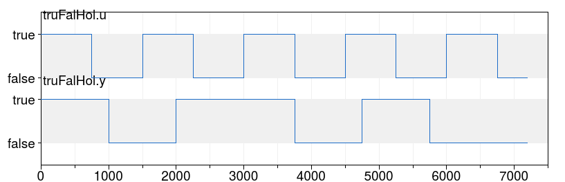
Block that holds a true or false signal for at least a defined time period.
Whenever the input u switches, the output y
switches and remains at that value for at least duration
seconds, where duration is a parameter.
After duration elapsed, the output will be
y = u.
If this change required changing the value of y,
then y will remain at that value for at least duration.
Otherwise, y will change immediately whenever u
changes.
This block could for example be used to disable an economizer, and not re-enable it for 10 minutes, and vice versa.
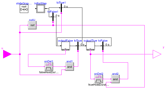
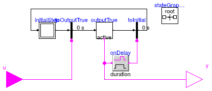
The image below shows the implementation with a state graph in which
each transition is only triggered when the input has the corresponding value,
and the current state has been active for at least duration seconds.
Simulation results of a typical example with duration = 1000 seconds.
Parameters
| Type | Name | Default | Description |
|---|---|---|---|
| Time | trueHoldDuration | true hold duration [s] | |
| Time | falseHoldDuration | trueHoldDuration | false hold duration [s] |
Connectors
| Type | Name | Description |
|---|---|---|
| input BooleanInput | u | Boolean input signal |
| output BooleanOutput | y | Boolean output signal |
Modelica definition
 Buildings.Controls.OBC.CDL.Logical.TrueHoldWithReset
Block that holds a true signal for at least a requested duration
Information
Block that holds a true input signal for at least a defined time period.
At initialization, the output y is equal to the input u.
If the input u becomes true, or is true
during intialization, a timer starts
and the Boolean output y stays true for the time
period provided by the parameter duration.
When this time is elapsed, the input is checked again. If
it is true, then the timer is restarted and the output remains
true for another duration seconds.
If the input u is false after
holdTime seconds, then the ouput is switched to false,
until the input becomes true again.
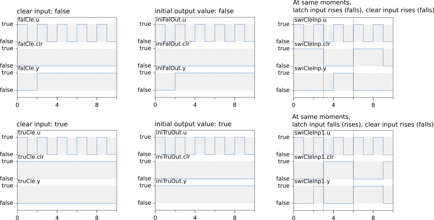
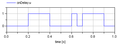
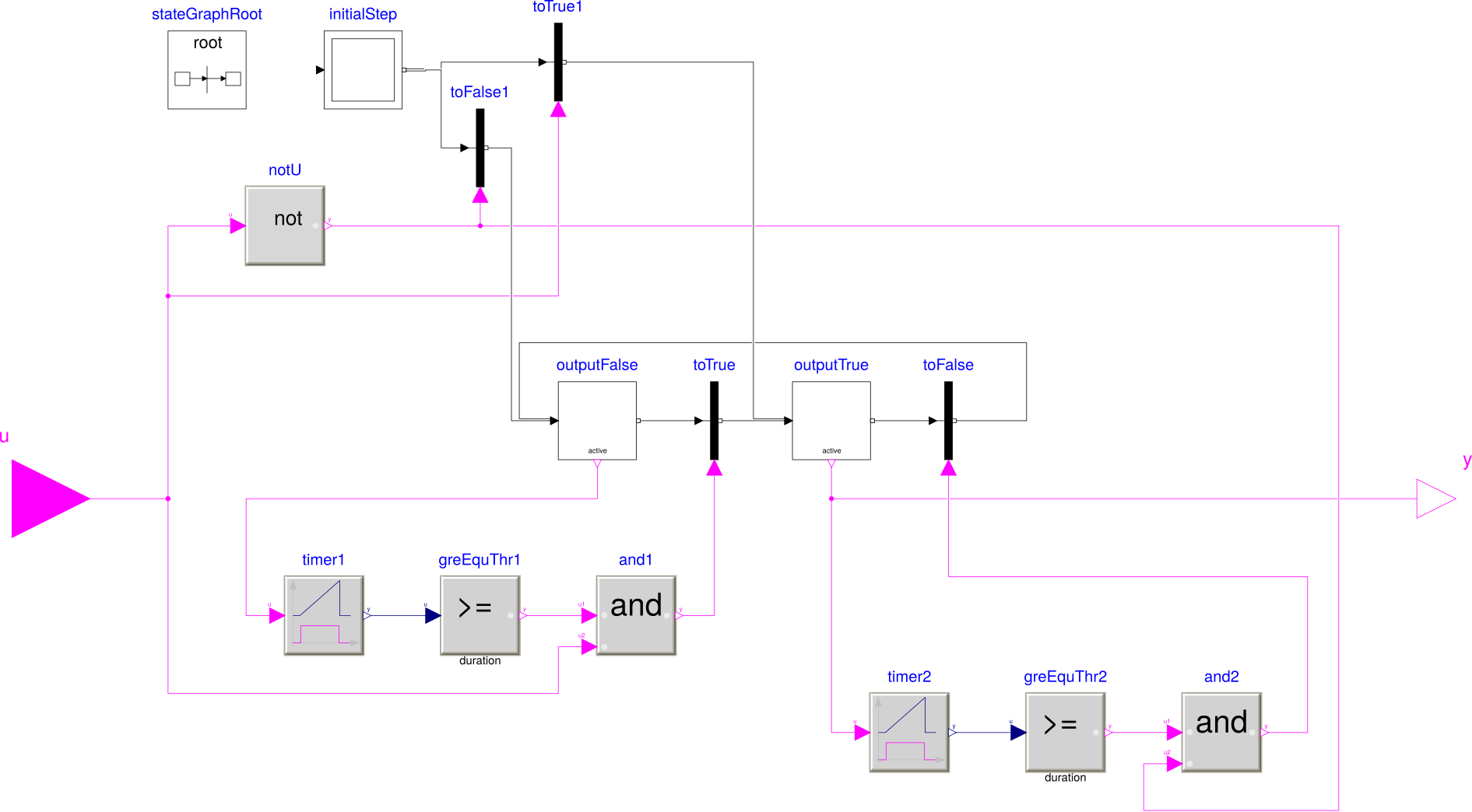
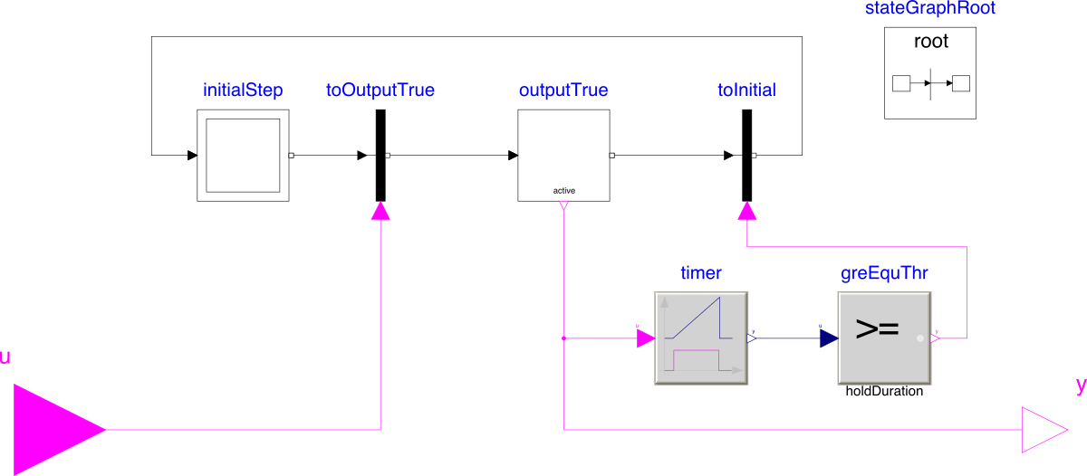
The figure below shows the state chart of the implementation. Note that the transition are done in zero time.
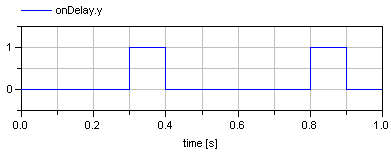
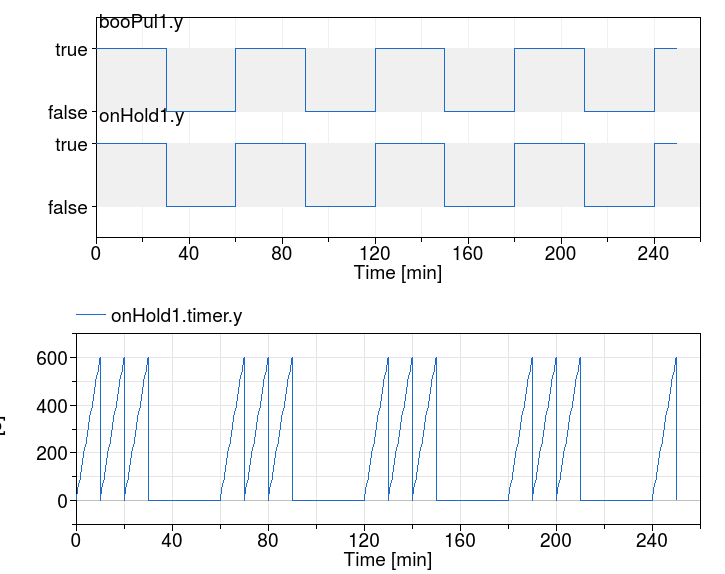
The figure below shows an example with a hold time of 3600 seconds and a pulse width period 9000 seconds that starts at t=200 seconds.
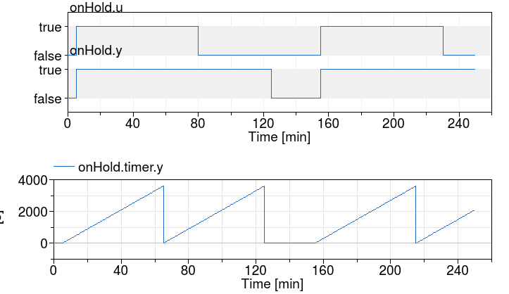
The figure below shows an example with a hold time of 60 seconds and a pulse width period 3600 seconds that starts at t=0 seconds.
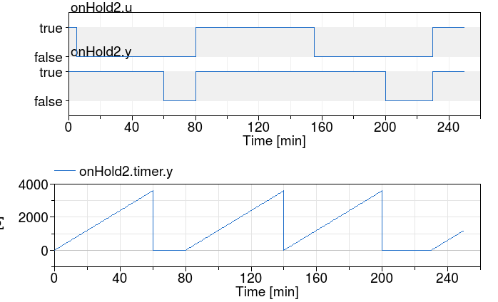
The next two figures show the same experiment, except that the input u
has been negated. The figure below has again a hold time of 3600 seconds
and a pulse width period 9000 seconds that starts at t=200 seconds.
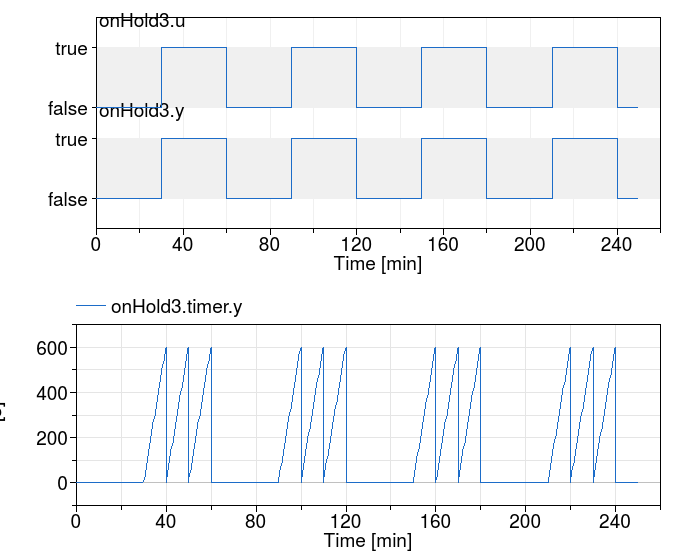
The figure below has again a hold time of 60 seconds and a pulse width period 3600 seconds that starts at t=0 seconds.
Parameters
| Type | Name | Default | Description |
|---|---|---|---|
| Time | duration | Time duration of the true output signal hold [s] |
Connectors
| Type | Name | Description |
|---|---|---|
| input BooleanInput | u | Boolean input signal |
| output BooleanOutput | y | Boolean output signal |
Modelica definition
 Buildings.Controls.OBC.CDL.Logical.Xor
Logical 'xor': y = u1 xor u2

Information
Block that outputs true if exactly one input is true.
Otherwise the output is false.
Connectors
| Type | Name | Description |
|---|---|---|
| input BooleanInput | u1 | Connector of first Boolean input signal |
| input BooleanInput | u2 | Connector of second Boolean input signal |
| output BooleanOutput | y | Connector of Boolean output signal |
Modelica definition
 Buildings.Controls.OBC.CDL.Logical.ZeroCrossing
Trigger zero crossing of input u
Information
Block that detects zero crossings.
The output y is true at the
time instant when the input u becomes
zero, provided the input enable is
true. At all other time instants,
the output y is false.
If the input u is zero at a time instant when
the enable
input changes its value, then the output y is false.
Note, that in the plot window of a Modelica simulator, the output of
this block is usually identically to false, because the output
may only be true at an event instant, but not during
continuous integration. In order to check that this component is
actually working as expected, one should connect its output to, e.g.,
component Buildings.Controls.OBC.CDL.Discrete.TriggeredSampler.
Connectors
| Type | Name | Description |
|---|---|---|
| input RealInput | u | Connector of Real input signal |
| output BooleanOutput | y | Connector of Boolean output signal |
| input BooleanInput | enable | Zero input crossing is triggered if the enable input signal is true |