Buildings.Applications.DataCenters.ChillerCooled.Controls.Validation
Collection of validation models
Information
This package contains validation models for the classes in Buildings.Applications.DataCenters.ChillerCooled.Controls.
Note that most validation models contain simple input data which may not be realistic, but for which the correct output can be obtained through an analytic solution. The examples plot various outputs, which have been verified against these solutions. These model outputs are stored as reference data and used for continuous validation whenever models in the library change.
Extends from Modelica.Icons.ExamplesPackage (Icon for packages containing runnable examples).
Package Content
| Name | Description |
|---|---|
| Test the model ChillerWSE.Examples.BaseClasses.ChillerStageControl | |
| Test the model ChillerWSE.Examples.BaseClasses.ConstatnSpeedPumpStageControl | |
| Test the model ChillerWSE.Examples.BaseClasses.CoolingModeController | |
| Example that illustrates the use of Buildings.Applications.DataCenters.ChillerCooled.Controls.CoolingModeNonIntegrated | |
| Test the model ChillerWSE.Examples.BaseClasses.CoolingTowerSpeedControl | |
| Test model for reheater controller | |
| Test the model ChillerWSE.Examples.BaseClasses.VariableSpeedPumpStageControl |
 Buildings.Applications.DataCenters.ChillerCooled.Controls.Validation.ChillerStage
Test the model ChillerWSE.Examples.BaseClasses.ChillerStageControl
Information
This example test the chiller staging controller implemented in Buildings.Applications.DataCenters.ChillerCooled.Controls.ChillerStage.
The number of running chillers is determined by cooling mode signal and total cooling load. In Free Cooling (FC) mode, no chillers are required; in Partial Mechanic Cooling (PMC) mode and Fully Mechanic Cooling (FMC) mode, chillers are required to run and the running number is based on cooling load. Details can be found in Buildings.Applications.DataCenters.ChillerCooled.Controls.ChillerStage.
Extends from Modelica.Icons.Example (Icon for runnable examples).
Modelica definition
Buildings.Applications.DataCenters.ChillerCooled.Controls.Validation.ConstantSpeedPumpStage
Test the model ChillerWSE.Examples.BaseClasses.ConstatnSpeedPumpStageControl
Information
This example test how the number of required constant-speed pumps varies based on cooling mode signals and the number of running chillers. Detailed control logic can be found in Buildings.Applications.DataCenters.ChillerCooled.Controls.ConstantSpeedPumpStage.
Extends from Modelica.Icons.Example (Icon for runnable examples).
Modelica definition
Buildings.Applications.DataCenters.ChillerCooled.Controls.Validation.CoolingMode
Test the model ChillerWSE.Examples.BaseClasses.CoolingModeController
Information
This model tests the cooling mode controller implemented in Buildings.Applications.DataCenters.ChillerCooled.Controls.CoolingMode.
Extends from Modelica.Icons.Example (Icon for runnable examples).
Modelica definition
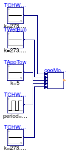
Buildings.Applications.DataCenters.ChillerCooled.Controls.Validation.CoolingModeNonIntegrated
Example that illustrates the use of Buildings.Applications.DataCenters.ChillerCooled.Controls.CoolingModeNonIntegrated
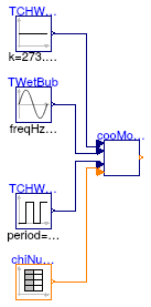
Information
This model tests the cooling mode controller implemented in Buildings.Applications.DataCenters.ChillerCooled.Controls.CoolingModeNonIntegrated.
Extends from Modelica.Icons.Example (Icon for runnable examples).
Modelica definition
Buildings.Applications.DataCenters.ChillerCooled.Controls.Validation.CoolingTowerSpeed
Test the model ChillerWSE.Examples.BaseClasses.CoolingTowerSpeedControl
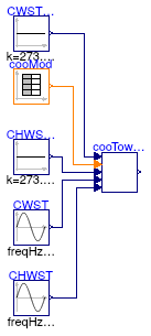
Information
This example tests the controller for the cooling tower fan speed. Detailed control logic can be found in Buildings.Applications.DataCenters.ChillerCooled.Controls.CoolingTowerSpeed.
Extends from Modelica.Icons.Example (Icon for runnable examples).
Parameters
| Type | Name | Default | Description |
|---|---|---|---|
| Controller | |||
| SimpleController | controllerType | Modelica.Blocks.Types.Simple... | Type of controller |
| Real | k | 1 | Gain of controller [1] |
| Time | Ti | 0.5 | Time constant of integrator block [s] |
| Time | Td | 0.1 | Time constant of derivative block [s] |
| Real | yMax | 1 | Upper limit of output |
| Real | yMin | 0 | Lower limit of output |
Modelica definition
Buildings.Applications.DataCenters.ChillerCooled.Controls.Validation.Reheat
Test model for reheater controller
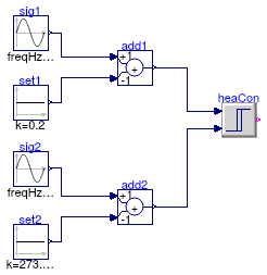
Information
This example tests the reheater controller with two varing input error signals.
Extends from Modelica.Icons.Example (Icon for runnable examples).
Modelica definition
Buildings.Applications.DataCenters.ChillerCooled.Controls.Validation.VariableSpeedPumpStage
Test the model ChillerWSE.Examples.BaseClasses.VariableSpeedPumpStageControl
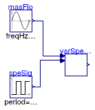
Information
This model test the staging controller for variable-speed pumps. The staging controller is located in Buildings.Applications.DataCenters.ChillerCooled.Controls.VariableSpeedPumpStage.
Extends from Modelica.Icons.Example (Icon for runnable examples).
Parameters
| Type | Name | Default | Description |
|---|---|---|---|
| MassFlowRate | m_flow_nominal | 100 | Nominal mass flowrate [kg/s] |