Buildings.Air.Systems.SingleZone.VAV
VAV system model
Information
VAV system model that serves a single thermal zone.
Extends from Modelica.Icons.Package (Icon for standard packages).
Package Content
| Name | Description |
|---|---|
| HVAC system model with a dry cooling coil, air-cooled chiller, electric heating coil, variable speed fan, and mixing box with economizer control. | |
| Controller for single zone VAV system | |
| Collection of models that illustrate model use and test models | |
| Package with base classes for Buildings.Air.Systems.SingleZone.VAV |
 Buildings.Air.Systems.SingleZone.VAV.ChillerDXHeatingEconomizer
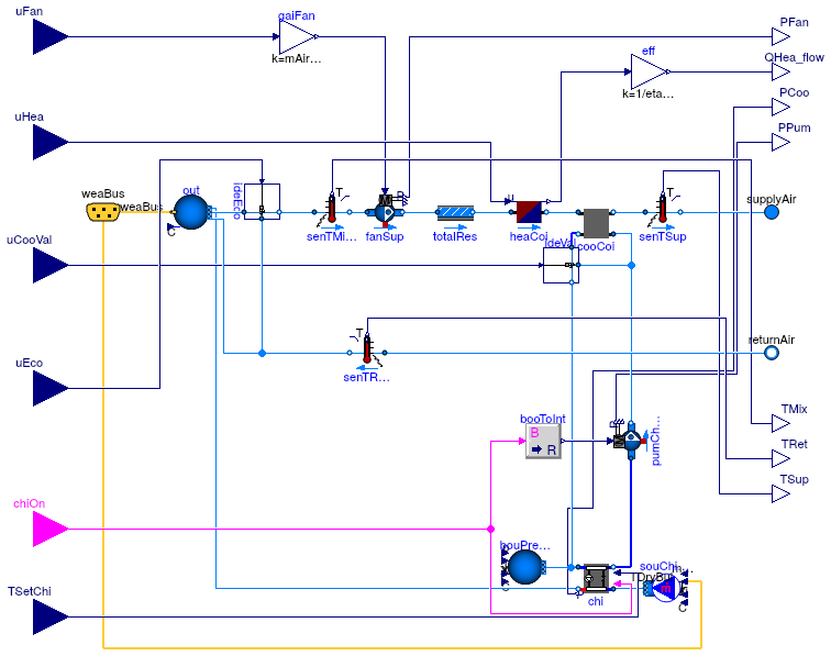
HVAC system model with a dry cooling coil, air-cooled chiller, electric heating coil, variable speed fan, and mixing box with economizer control.

Information
This is a conventional single zone VAV HVAC system model. The system contains a variable speed supply fan, electric heating coil, water-based cooling coil, economizer, and air-cooled chiller. The control of the system is that of conventional VAV heating and cooling. During cooling, the supply air temperature is held constant while the supply air flow is modulated from maximum to minimum according to zone load. This is done by modulating the fan speed. During heating, the supply air flow is held at a constant minimum while the heating coil is modulated accoding to zone load. The mass flow of chilled water through the cooling coil is controlled by a three-way valve to maintain the supply air temperature setpoint during cooling. The mixing box maintains the minimum outside airflow fraction unless conditions for economizer are met, in which case the economizer controller adjusts the outside airflow fraction to meet a mixed air temperature setpoint. The economizer is enabled if the outside air drybulb temperature is lower than the return air temperature and the system is not in heating mode.
There are a number of assumptions in the model. Pressure drops through the system are collected into a single component. The mass flow of return air is equal to the mass flow of supply air. The mass flow of outside air and relief air in the mixing box is ideally controlled so that the supply air is composed of the specified outside airflow fraction, rather than having feedback control of damper positions. The cooling coil is a dry coil model.
Parameters
| Type | Name | Default | Description |
|---|---|---|---|
| replaceable package MediumA | Buildings.Media.Air | Medium model for air | |
| replaceable package MediumW | Buildings.Media.Water | Medium model for water | |
| DimensionlessRatio | COP_nominal | 5.5 | Nominal COP of the chiller [1] |
| Temperature | TSupChi_nominal | Design value for chiller leaving water temperature [K] | |
| Air design | |||
| MassFlowRate | mAir_flow_nominal | Design airflow rate of system [kg/s] | |
| PressureDifference | dp_nominal | 500 | Design pressure drop of flow leg with fan [Pa] |
| Heating design | |||
| Power | QHea_flow_nominal | QHea_flow_nominal(min=0) | Design heating capacity of heating coil [W] |
| Real | etaHea_nominal | etaHea_nominal(min=0, max=1,... | Design heating efficiency of the heating coil [1] |
| Cooling design | |||
| Power | QCoo_flow_nominal | QCoo_flow_nominal(max=0) | Design heating capacity of cooling coil [W] |
Connectors
| Type | Name | Description |
|---|---|---|
| replaceable package MediumA | Medium model for air | |
| replaceable package MediumW | Medium model for water | |
| input BooleanInput | chiOn | On signal for chiller plant |
| input RealInput | uFan | Fan control signal [1] |
| input RealInput | uHea | Control input for heater [1] |
| input RealInput | uCooVal | Control signal for cooling valve [1] |
| input RealInput | TSetChi | Set point for leaving chilled water temperature [K] |
| input RealInput | uEco | Control signal for economizer |
| FluidPort_a | supplyAir | Supply air |
| FluidPort_b | returnAir | Return air |
| output RealOutput | PFan | Electrical power consumed by the supply fan [W] |
| output RealOutput | QHea_flow | Electrical power consumed by the heating equipment [W] |
| output RealOutput | PCoo | Electrical power consumed by the cooling equipment [W] |
| output RealOutput | PPum | Electrical power consumed by the pumps [W] |
| output RealOutput | TMix | Mixed air temperature [K] |
| output RealOutput | TSup | Supply air temperature after coils [K] |
| Bus | weaBus | Weather bus |
| output RealOutput | TRet | Return air temperature [K] |
Modelica definition
 Buildings.Air.Systems.SingleZone.VAV.ChillerDXHeatingEconomizerController
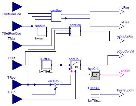
Controller for single zone VAV system

Information
This is the controller for the VAV system with economizer, heating coil and cooling coil.
Extends from Modelica.Blocks.Icons.Block (Basic graphical layout of input/output block).
Parameters
| Type | Name | Default | Description |
|---|---|---|---|
| Temperature | TSupChi_nominal | Design value for chiller leaving water temperature [K] | |
| Air design | |||
| Real | minAirFlo | 0.2 | Minimum airflow rate of system [1] |
| DimensionlessRatio | minOAFra | Minimum outdoor air fraction of system [1] | |
| Temperature | TSetSupAir | Cooling supply air temperature setpoint [K] | |
| Control gain | |||
| Real | kHea | 2 | Gain of heating controller |
| Real | kCoo | 1 | Gain of controller for cooling valve |
| Real | kFan | 0.5 | Gain of controller for fan |
| Real | kEco | 4 | Gain of controller for economizer |
Connectors
| Type | Name | Description |
|---|---|---|
| input RealInput | TRoo | Zone temperature measurement [K] |
| input RealInput | TSetRooCoo | Zone cooling setpoint temperature [K] |
| input RealInput | TSetRooHea | Zone heating setpoint temperature [K] |
| input RealInput | TMix | Measured mixed air temperature [K] |
| input RealInput | TSup | Measured supply air temperature after the cooling coil [K] |
| input RealInput | TOut | Measured outside air temperature [K] |
| output RealOutput | yHea | Control signal for heating coil [1] |
| output RealOutput | yFan | Control signal for fan [1] |
| output RealOutput | yOutAirFra | Control signal for outside air fraction [1] |
| output RealOutput | yCooCoiVal | Control signal for cooling coil valve [1] |
| output RealOutput | TSetSupChi | Set point for chiller leaving water temperature [K] |
| output BooleanOutput | chiOn | On signal for chiller |
Modelica definition
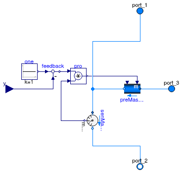
 Buildings.Air.Systems.SingleZone.VAV.ChillerDXHeatingEconomizer.IdealValve

Information
Extends from Modelica.Blocks.Icons.Block (Basic graphical layout of input/output block).
Parameters
| Type | Name | Default | Description |
|---|---|---|---|
| replaceable package Medium | Modelica.Media.Interfaces.Pa... | Medium in the component | |
| MassFlowRate | m_flow_nominal | Design chilled water supply flow [kg/s] | |
Connectors
| Type | Name | Description |
|---|---|---|
| replaceable package Medium | Medium in the component | |
| FluidPort_a | port_1 | |
| FluidPort_b | port_2 | |
| FluidPort_a | port_3 | |
| input RealInput | y | |
