Buildings.Fluid.HeatExchangers.Validation
Collection of models that validate the heat exchanger models
Information
This package contains models that validate the heat exchanger models. The examples plot various outputs, which have been verified against analytical solutions. These model outputs are stored as reference data to allow continuous validation whenever models in the library change.
Extends from Modelica.Icons.ExamplesPackage (Icon for packages containing runnable examples).
Package Content
| Name | Description |
|---|---|
| Model that demonstrates use of a heat exchanger with constant effectiveness | |
| Test model for the evaporator or condenser model | |
| Model that demonstrates the ideal heater model | |
| Model that demonstrates the ideal heater/cooler model for a prescribed outlet temperature, configured as steady-state | |
| Model that demonstrates the ideal heater/cooler model for a prescribed outlet temperature, configured as dynamic | |
| Model that demonstrates use of a finite volume model of a heat exchanger with condensation | |
| Model that demonstrates use of a finite volume model of a heat exchanger with condensation |
 Buildings.Fluid.HeatExchangers.Validation.ConstantEffectiveness
Model that demonstrates use of a heat exchanger with constant effectiveness
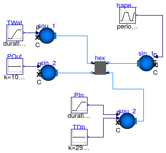
Information
This model tests Buildings.Fluid.HeatExchangers.ConstantEffectiveness for different inlet conditions.
Extends from Modelica.Icons.Example (Icon for runnable examples).
Modelica definition
Buildings.Fluid.HeatExchangers.Validation.EvaporatorCondenser
Test model for the evaporator or condenser model
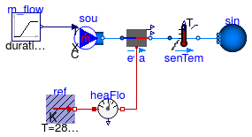
Information
Model that demonstrates the use of the Buildings.Fluid.HeatExchangers.EvaporatorCondenser model.
The fluid flow rate is increased from ṁ = 0.01 kg/s to ṁ = 0.10 kg/s over 100 seconds. As a result, the heat exchanger effectiveness and the fluid temperature difference in the heat exchanger decrease.
Extends from Modelica.Icons.Example (Icon for runnable examples).
Parameters
| Type | Name | Default | Description |
|---|---|---|---|
| MassFlowRate | m_flow_nominal | 0.01 | Nominal mass flow rate [kg/s] |
Modelica definition
Buildings.Fluid.HeatExchangers.Validation.HeaterCooler_u
Model that demonstrates the ideal heater model
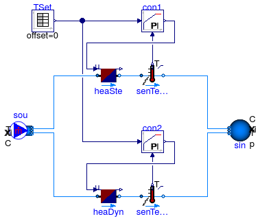
Information
Model that demonstrates the use of an ideal heater. Both heater models are identical, except that one model is configured as a steady-state model, whereas the other is configured as a dynamic model. Both heaters add heat to the medium to track a set-point for the outlet temperature.
Extends from Modelica.Icons.Example (Icon for runnable examples).
Parameters
| Type | Name | Default | Description |
|---|---|---|---|
| MassFlowRate | m_flow_nominal | 3000/1000/20 | Nominal mass flow rate [kg/s] |
Modelica definition
Buildings.Fluid.HeatExchangers.Validation.PrescribedOutlet
Model that demonstrates the ideal heater/cooler model for a prescribed outlet temperature, configured as steady-state
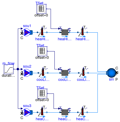
Information
Model that demonstrates the use of an ideal heater and an ideal cooler.
The heater model has a capacity of Q_flow_max = 1.0e4 Watts and
the cooler model has a capacitiy of Q_flow_min = -1000 Watts.
Hence, both only track their set point of the outlet temperature during certain times.
There is also a heater and cooler with unlimited capacity.
At t=1000 second, the flow reverses its direction.
Each flow leg has the same mass flow rate. There are three mass flow sources as using one source only would yield a nonlinear system of equations that needs to be solved to determine the mass flow rate distribution.
Extends from Modelica.Icons.Example (Icon for runnable examples).
Parameters
| Type | Name | Default | Description |
|---|---|---|---|
| MassFlowRate | m_flow_nominal | 0.1 | Nominal mass flow rate [kg/s] |
Modelica definition
Buildings.Fluid.HeatExchangers.Validation.PrescribedOutlet_dynamic
Model that demonstrates the ideal heater/cooler model for a prescribed outlet temperature, configured as dynamic
Information
Model that demonstrates the use of an ideal heater and an ideal cooler, configured as dynamic models.
This example is identical to Buildings.Fluid.HeatExchangers.Validation.PrescribedOutlet except that the heater and cooler models are configured to have a time constant of 60 seconds at nominal flow rate. At lower flow rate, the time constant increases proportional to the mass flow rate.
Extends from Buildings.Fluid.HeatExchangers.Validation.PrescribedOutlet (Model that demonstrates the ideal heater/cooler model for a prescribed outlet temperature, configured as steady-state).
Parameters
| Type | Name | Default | Description |
|---|---|---|---|
| MassFlowRate | m_flow_nominal | 0.1 | Nominal mass flow rate [kg/s] |
Modelica definition
Buildings.Fluid.HeatExchangers.Validation.WetCoilDiscretizedInitialization
Model that demonstrates use of a finite volume model of a heat exchanger with condensation
Information
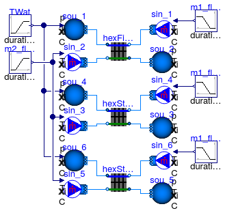
This model is used to test the initialization of the coil model. There are three instances of the coil model, each having different settings for the initial conditions. Each of the coil uses for the medium Buildings.Media.Air.
Extends from Buildings.Fluid.HeatExchangers.Examples.BaseClasses.WetCoilDiscretized (Model that demonstrates use of a finite volume model of a heat exchanger with condensation), Modelica.Icons.Example (Icon for runnable examples).
Parameters
| Type | Name | Default | Description |
|---|---|---|---|
| replaceable package Medium2 | PartialMedium | Medium for air-side | |
| Temperature | T_a1_nominal | 5 + 273.15 | Water inlet temperature [K] |
| Temperature | T_b1_nominal | 10 + 273.15 | Water outlet temperature [K] |
| Temperature | T_a2_nominal | 30 + 273.15 | Air inlet temperature [K] |
| Temperature | T_b2_nominal | 10 + 273.15 | Air inlet temperature [K] |
| MassFlowRate | m1_flow_nominal | 5 | Nominal mass flow rate water-side [kg/s] |
| MassFlowRate | m2_flow_nominal | m1_flow_nominal*4200/1000*(T... | Nominal mass flow rate air-side [kg/s] |
Connectors
| Type | Name | Description |
|---|---|---|
| replaceable package Medium2 | Medium for air-side | |
Modelica definition
Buildings.Fluid.HeatExchangers.Validation.WetCoilDiscretizedInitializationPerfectGases
Model that demonstrates use of a finite volume model of a heat exchanger with condensation
Information
This model is used to test the initialization of the coil model. There are three instances of the coil model, each having different settings for the initial conditions. Each of the coil uses for the medium Buildings.Media.Air.
Extends from Buildings.Fluid.HeatExchangers.Examples.BaseClasses.WetCoilDiscretized (Model that demonstrates use of a finite volume model of a heat exchanger with condensation), Modelica.Icons.Example (Icon for runnable examples).
Parameters
| Type | Name | Default | Description |
|---|---|---|---|
| replaceable package Medium2 | PartialMedium | Medium for air-side | |
| Temperature | T_a1_nominal | 5 + 273.15 | Water inlet temperature [K] |
| Temperature | T_b1_nominal | 10 + 273.15 | Water outlet temperature [K] |
| Temperature | T_a2_nominal | 30 + 273.15 | Air inlet temperature [K] |
| Temperature | T_b2_nominal | 10 + 273.15 | Air inlet temperature [K] |
| MassFlowRate | m1_flow_nominal | 5 | Nominal mass flow rate water-side [kg/s] |
| MassFlowRate | m2_flow_nominal | m1_flow_nominal*4200/1000*(T... | Nominal mass flow rate air-side [kg/s] |
Connectors
| Type | Name | Description |
|---|---|---|
| replaceable package Medium2 | Medium for air-side | |