Buildings.Fluid.FixedResistances.BaseClasses
Package with base classes for Buildings.Fluid.FixedResistances
Information
This package contains base classes that are used to construct the models in Buildings.Fluid.FixedResistances.
Extends from Modelica.Icons.BasesPackage (Icon for packages containing base classes).
Package Content
| Name | Description |
|---|---|
| Model of a pipe with finite volume discretization along the flow path | |
| Lossless pipe model with spatialDistribution plug flow implementation | |
| Pipe model using spatialDistribution for temperature delay with modified delay tracker | |
| Heat loss model for pipe with delay as an input variable | |
| Delay time for given normalized velocity | |
| Collection of validation models |
 Buildings.Fluid.FixedResistances.BaseClasses.Pipe
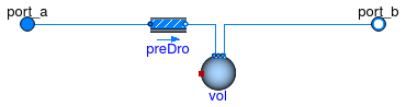
Model of a pipe with finite volume discretization along the flow path
Information
Model of a pipe with flow resistance and optional heat storage.
This model can be used for modeling the heat exchange between the pipe and environment.
The model consists of a flow resistance
Buildings.Fluid.FixedResistances.PressureDrop
and nSeg mixing volumes
Buildings.Fluid.MixingVolumes.MixingVolume.
Extends from Buildings.Fluid.Interfaces.LumpedVolumeDeclarations (Declarations for lumped volumes), Buildings.Fluid.Interfaces.PartialTwoPortInterface (Partial model transporting fluid between two ports without storing mass or energy), Buildings.Fluid.Interfaces.TwoPortFlowResistanceParameters (Parameters for flow resistance for models with two ports).
Parameters
| Type | Name | Default | Description |
|---|---|---|---|
| replaceable package Medium | PartialMedium | Medium in the component | |
| Integer | nSeg | 10 | Number of volume segments |
| Length | thicknessIns | Thickness of insulation [m] | |
| ThermalConductivity | lambdaIns | Heat conductivity of insulation [W/(m.K)] | |
| Length | diameter | Pipe diameter (without insulation) [m] | |
| Length | length | Length of the pipe [m] | |
| Nominal condition | |||
| MassFlowRate | m_flow_nominal | Nominal mass flow rate [kg/s] | |
| PressureDifference | dp_nominal | Pressure difference [Pa] | |
| Dynamics | |||
| Equations | |||
| Dynamics | energyDynamics | Modelica.Fluid.Types.Dynamic... | Type of energy balance: dynamic (3 initialization options) or steady state |
| Dynamics | massDynamics | energyDynamics | Type of mass balance: dynamic (3 initialization options) or steady state |
| Real | mSenFac | 1 | Factor for scaling the sensible thermal mass of the volume |
| Initialization | |||
| AbsolutePressure | p_start | Medium.p_default | Start value of pressure [Pa] |
| Temperature | T_start | Medium.T_default | Start value of temperature [K] |
| MassFraction | X_start[Medium.nX] | Medium.X_default | Start value of mass fractions m_i/m [kg/kg] |
| ExtraProperty | C_start[Medium.nC] | fill(0, Medium.nC) | Start value of trace substances |
| ExtraProperty | C_nominal[Medium.nC] | fill(1E-2, Medium.nC) | Nominal value of trace substances. (Set to typical order of magnitude.) |
| Assumptions | |||
| Boolean | allowFlowReversal | true | = false to simplify equations, assuming, but not enforcing, no flow reversal |
| Advanced | |||
| MassFlowRate | m_flow_small | 1E-4*abs(m_flow_nominal) | Small mass flow rate for regularization of zero flow [kg/s] |
| Boolean | homotopyInitialization | true | = true, use homotopy method |
| Diagnostics | |||
| Boolean | show_T | true | = true, if actual temperature at port is computed |
| Flow resistance | |||
| Boolean | computeFlowResistance | (abs(dp_nominal) > Modelica.... | =true, compute flow resistance. Set to false to assume no friction |
| Boolean | from_dp | false | = true, use m_flow = f(dp) else dp = f(m_flow) |
| Boolean | linearizeFlowResistance | false | = true, use linear relation between m_flow and dp for any flow rate |
| Real | deltaM | 0.1 | Fraction of nominal flow rate where flow transitions to laminar |
| Real | ReC | 4000 | Reynolds number where transition to turbulent starts |
Connectors
| Type | Name | Description |
|---|---|---|
| FluidPort_a | port_a | Fluid connector a (positive design flow direction is from port_a to port_b) |
| FluidPort_b | port_b | Fluid connector b (positive design flow direction is from port_a to port_b) |
Modelica definition
 Buildings.Fluid.FixedResistances.BaseClasses.PlugFlow
Lossless pipe model with spatialDistribution plug flow implementation

Information
Model that computes the temperature propagation of a fluid flow through a pipe, idealized as a plug flow.
Main equation
The transport delay is computed using the one-dimensional wave equation without source or sink terms,
∂z(x,t)/∂t + v(t) ∂z(x,t)/∂x = 0,
where z(x,t) is the spatial distribution as a function of time of any property z of the fluid. For the temperature propagation, z will be replaced by T.
Assumptions
This model is based on the following assumptions:
- Axial diffusion in water is assumed to be negligibe.
- The water temperature is assumed uniform in a cross section.
Extends from Buildings.Fluid.Interfaces.PartialTwoPort (Partial component with two ports).
Parameters
| Type | Name | Default | Description |
|---|---|---|---|
| replaceable package Medium | PartialMedium | Medium in the component | |
| Length | dh | Hydraulic diameter (assuming a round cross section area) [m] | |
| Length | length | Pipe length [m] | |
| Initialization | |||
| Temperature | T_start_in | Medium.T_default | Initial temperature in pipe at inlet [K] |
| Temperature | T_start_out | Medium.T_default | Initial temperature in pipe at outlet [K] |
| Assumptions | |||
| Boolean | allowFlowReversal | true | = false to simplify equations, assuming, but not enforcing, no flow reversal |
| Advanced | |||
| MassFlowRate | m_flow_small | Small mass flow rate for regularization of zero flow [kg/s] | |
Connectors
| Type | Name | Description |
|---|---|---|
| FluidPort_a | port_a | Fluid connector a (positive design flow direction is from port_a to port_b) |
| FluidPort_b | port_b | Fluid connector b (positive design flow direction is from port_a to port_b) |
Modelica definition
 Buildings.Fluid.FixedResistances.BaseClasses.PlugFlowCore
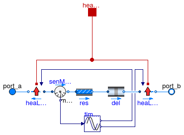
Pipe model using spatialDistribution for temperature delay with modified delay tracker
Information
Pipe with heat loss using the time delay based heat losses and plug flow for the transport delay of the fluid.
Implementation
The
spatialDistribution operator is used for the temperature wave propagation
through the length of the pipe. This operator is contained in
BaseClasses.PlugFlow.
This model does not include thermal inertia of the pipe wall.
The wall inertia is implemented in
PlugFlowPipe, which uses this model.
The removal of the thermal inertia with a mixing volume can be desirable in the
case where mixing volumes are added manually at the pipe junctions.
The model PlugFlowHeatLoss implements a heat loss in design direction, but leaves the enthalpy unchanged in opposite flow direction. Therefore it is used in front of and behind the time delay.
References
Full details on the model implementation and experimental validation can be found in:
van der Heijde, B., Fuchs, M., Ribas Tugores, C., Schweiger, G., Sartor, K., Basciotti, D., Müller,
D., Nytsch-Geusen, C., Wetter, M. and Helsen, L. (2017).
Dynamic equation-based thermo-hydraulic pipe model for district heating and cooling systems.
Energy Conversion and Management, vol. 151, p. 158-169.
doi: 10.1016/j.enconman.2017.08.072.
Extends from Buildings.Fluid.Interfaces.PartialTwoPort (Partial component with two ports).
Parameters
| Type | Name | Default | Description |
|---|---|---|---|
| replaceable package Medium | PartialMedium | Medium in the component | |
| Length | dh | Hydraulic diameter (assuming a round cross section area) [m] | |
| Length | length | Pipe length [m] | |
| Real | R | Thermal resistance per unit length from fluid to boundary temperature [(m.K)/W] | |
| Real | C | Thermal capacity per unit length of pipe [J/(K.m)] | |
| Real | fac | 1 | Factor to take into account flow resistance of bends etc., fac=dp_nominal/dpStraightPipe_nominal |
| Length | thickness | Pipe wall thickness [m] | |
| Real | ReC | 4000 | Reynolds number where transition to turbulent starts |
| Nominal condition | |||
| Velocity | v_nominal | Velocity at m_flow_nominal (used to compute default value for hydraulic diameter dh) [m/s] | |
| MassFlowRate | m_flow_nominal | Nominal mass flow rate [kg/s] | |
| Geometry | |||
| Height | roughness | 2.5e-5 | Average height of surface asperities (default: smooth steel pipe) [m] |
| Assumptions | |||
| Boolean | allowFlowReversal | true | = false to simplify equations, assuming, but not enforcing, no flow reversal |
| Advanced | |||
| MassFlowRate | m_flow_small | 1E-4*abs(m_flow_nominal) | Small mass flow rate for regularization of zero flow [kg/s] |
| Boolean | from_dp | false | = true, use m_flow = f(dp) else dp = f(m_flow) |
| Boolean | homotopyInitialization | true | = true, use homotopy method |
| Boolean | linearized | false | = true, use linear relation between m_flow and dp for any flow rate |
| Initialization | |||
| Temperature | T_start_in | Medium.T_default | Initialization temperature at pipe inlet [K] |
| Temperature | T_start_out | Medium.T_default | Initialization temperature at pipe outlet [K] |
| Boolean | initDelay | false | Initialize delay for a constant mass flow rate if true, otherwise start from 0 |
| MassFlowRate | m_flow_start | 0 | [kg/s] |
Connectors
| Type | Name | Description |
|---|---|---|
| FluidPort_a | port_a | Fluid connector a (positive design flow direction is from port_a to port_b) |
| FluidPort_b | port_b | Fluid connector b (positive design flow direction is from port_a to port_b) |
| HeatPort_a | heatPort | Heat port to connect environment (positive heat flow for heat loss to surroundings) |
Modelica definition
 Buildings.Fluid.FixedResistances.BaseClasses.PlugFlowHeatLoss
Heat loss model for pipe with delay as an input variable

Information
Component that calculates the heat losses at the end of a plug flow pipe when the flow goes in the design direction.
Main equations
The governing equations are
Tout = Tb + (Tin - Tb) exp((tout - tin)/tauchar)
with
tauchar = R C
Assumptions and limitations
This model is based on the following assumptions:
- The water temperature is uniform in the cross section.
- There is no axial heat transfer in the water or surrounding.
- The boundary temperature along the pipe is uniform.
- Heat losses are steady-state.
Implementation
Heat losses are only considered in design flow direction.
For heat loss consideration in both directions, use one of these models at
both ends of a
Buildings.Fluid.FixedResistances.BaseClasses.PlugFlow model.
The outlet temperature is calculated as in the equation above,
using the inlet temperature at port_a and the instantaneous
time delay and boundary temperature.
The boundary temperature can be either the air temperature
or the undisturbed ground temperature, depending on the definition of the
thermal resistance R.
This component requires the delay time and the instantaneous ambient temperature as an input. This component is to be used in single pipes or in more advanced configurations where no influence from other pipes is considered.
Extends from Fluid.Interfaces.PartialTwoPortTransport (Partial element transporting fluid between two ports without storage of mass or energy).
Parameters
| Type | Name | Default | Description |
|---|---|---|---|
| replaceable package Medium | PartialMedium | Medium in the component | |
| Real | C | Thermal capacity per unit length of pipe [J/(K.m)] | |
| Real | R | Thermal resistance per unit length from fluid to boundary temperature [(m.K)/W] | |
| MassFlowRate | m_flow_nominal | Nominal mass flow rate [kg/s] | |
| Temperature | T_start | Initial output temperature [K] | |
| Assumptions | |||
| Boolean | allowFlowReversal | true | = false to simplify equations, assuming, but not enforcing, no flow reversal |
| Advanced | |||
| PressureDifference | dp_start | 0 | Guess value of dp = port_a.p - port_b.p [Pa] |
| MassFlowRate | m_flow_start | 0 | Guess value of m_flow = port_a.m_flow [kg/s] |
| MassFlowRate | m_flow_small | Small mass flow rate for regularization of zero flow [kg/s] | |
| Diagnostics | |||
| Boolean | show_T | true | = true, if temperatures at port_a and port_b are computed |
| Boolean | show_V_flow | true | = true, if volume flow rate at inflowing port is computed |
Connectors
| Type | Name | Description |
|---|---|---|
| FluidPort_a | port_a | Fluid connector a (positive design flow direction is from port_a to port_b) |
| FluidPort_b | port_b | Fluid connector b (positive design flow direction is from port_a to port_b) |
| input RealInput | tau | Time delay at pipe level [s] |
| HeatPort_a | heatPort | Heat port to connect environment (negative if heat is lost to ambient) |
Modelica definition
 Buildings.Fluid.FixedResistances.BaseClasses.PlugFlowTransportDelay
Delay time for given normalized velocity

Information
Calculates time delay at both sides of the pipe as the difference between the current simulation time and the inlet time of the fluid at both ends of the pipe.
Main equation
∂z(x,t)/∂t + v(t) ∂z(x,t)/∂x = 0,
where z(x,t) is the spatial distribution as a function of time of any property z of the fluid. For the inlet time propagation, z will be replaced by the inlet time of the fluid tin.
Implementation
The inlet time is approached as a fluid property and its propagation follows the one-dimensional wave equation, implemented using the spatialDistribution function. This components requires the mass flow through the pipe and the pipe dimensions in order to derive information about the fluid propagation.
The component calculates the delay time at both in/outlet ports of the pipe and therefore has two outlets. During forward flow, only the forward Buildings.Fluid.PlugFlowPipes.BaseClasses.HeatLossPipeDelay component in Buildings.Fluid.PlugFlowPipes.BaseClasses.PipeCore will be active and uses the forward output of PlugFlowTransportDelay. During reverse, the opposite is true and only the reverse output is used.
Assumption
It is assumed that no axial mixing takes place in the pipe.
Parameters
| Type | Name | Default | Description |
|---|---|---|---|
| Length | length | Pipe length [m] | |
| Length | dh | Hydraulic diameter (assuming a round cross section area) [m] | |
| Density | rho | Standard density of fluid [kg/m3] | |
| Initialization | |||
| Boolean | initDelay | false | Initialize delay for a constant m_flow_start if true, otherwise start from 0 |
| MassFlowRate | m_flow_start | 0 | Initialization of mass flow rate to calculate initial time delay [kg/s] |
| Nominal condition | |||
| MassFlowRate | m_flow_nominal | Nominal mass flow rate [kg/s] | |
Connectors
| Type | Name | Description |
|---|---|---|
| input RealInput | m_flow | Mass flow of fluid |
| output RealOutput | tau | Time delay for design flow direction |
| output RealOutput | tauRev | Time delay for reverse flow |