Buildings.Fluid.FMI.ExportContainers.Validation
Collection of validation models
Information
This package contains validation models for the classes in Buildings.Fluid.FMI.ExportContainers.
Note that most validation models contain simple input data which may not be realistic, but for which the correct output can be obtained through an analytic solution. The examples plot various outputs, which have been verified against these solutions. These model outputs are stored as reference data and used for continuous validation whenever models in the library change.
Extends from Modelica.Icons.ExamplesPackage (Icon for packages containing runnable examples).
Package Content
| Name | Description |
|---|---|
| Validation model for connected single thermal zone and HVAC system | |
| Collection of validation models for FMU export |
 Buildings.Fluid.FMI.ExportContainers.Validation.RoomHVAC
Validation model for connected single thermal zone and HVAC system
Information
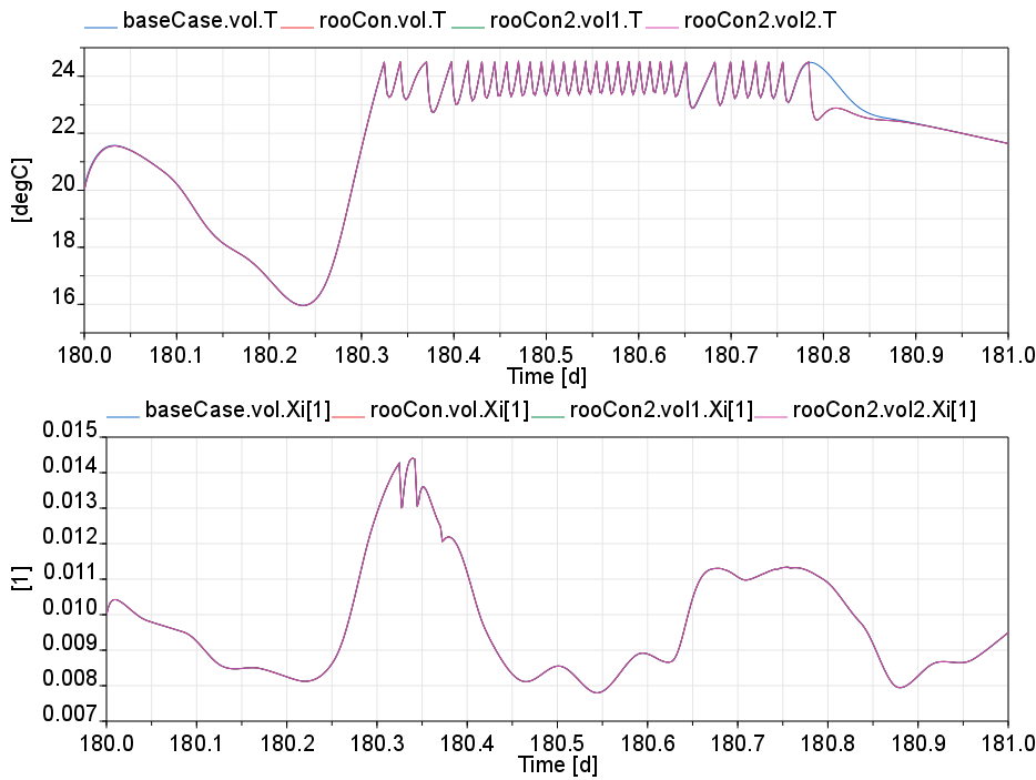
This example validates the coupling of convective thermal zones with air-based HVAC systems. The model has the following three parts:
-
The block
baseCaseis the base case model, which is adapted from Buildings.Examples.Tutorial.SpaceCooling.System3 to have the same flow resistances as the models that are here validated. -
The blocks
hvaConandrooConare FMU containers that contain an HVAC system for a single zone, and a thermal model of a single zone. Both models have the same configuration asbaseCase, but they are implemented such that the HVAC system and the thermal zone are in separate blocks. These blocks could be exported as an FMU, but here they are connected to each other to validate whether they indeed give the same response as the base casebaseCase. -
The blocks
hvaCon2androoCon2are again containers for HVAC and room models, but the models that they encapsulate are an HVAC system that serves two rooms, and a model of two thermal zones. Hence, this case tests whether the FMU containers for multiple HVAC systems, and for multiple thermal zones, are implemented correctly.
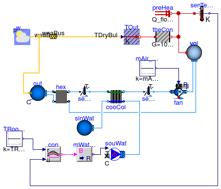
When the model is simulated, one sees that the air temperatures and the water
vapor mass fraction in all four room models are the same.
Note, however, that in Dymola 2017, the base case basCas
reaches in the last cooling cylce of the day not quite the set point, and hence
switches the cooling on time less than the other models.
We attribute this to numerical approximation errors that causes a slightly different
temperature trajectory.
With Dymola 2017, we obtain the trajectories shown below.
Extends from Modelica.Icons.Example (Icon for runnable examples).
Modelica definition
 Buildings.Fluid.FMI.ExportContainers.Validation.RoomHVAC.BaseCase
Base case model used for the validation of the FMI interfaces
Information
This example is the base case model which is used to validate the coupling of a convective thermal zone with an air-based HVAC system.
It is based on Buildings.Examples.Tutorial.SpaceCooling.System3, and it assign some parameters to have the same configuration as Buildings.Fluid.FMI.ExportContainers.Examples.FMUs.HVACZone.
The model which is validated using this model is Buildings.Fluid.FMI.ExportContainers.Validation.RoomHVAC .
Extends from Buildings.Examples.Tutorial.SpaceCooling.System3 (Third part of the system model with air supply and closed loop control).
Parameters
| Type | Name | Default | Description |
|---|---|---|---|
| replaceable package MediumA | Air | Medium for air | |
| replaceable package MediumW | Water | Medium for water | |
| Volume | V | 6*10*3 | Room volume [m3] |
| Real | eps | 0.8 | Heat recovery effectiveness |
| Temperature | TASup_nominal | 273.15 + 18 | Nominal air temperature supplied to room [K] |
| Temperature | TRooSet | 273.15 + 24 | Nominal room air temperature [K] |
| Temperature | TOut_nominal | 273.15 + 30 | Design outlet air temperature [K] |
| Temperature | THeaRecLvg | TOut_nominal - eps*(TOut_nom... | Air temperature leaving the heat recovery [K] |
| HeatFlowRate | QRooInt_flow | 1000 | Internal heat gains of the room [W] |
| HeatFlowRate | QRooC_flow_nominal | -QRooInt_flow - 10E3/30*(TOu... | Nominal cooling load of the room [W] |
| MassFlowRate | mA_flow_nominal | 1.3*QRooC_flow_nominal/1006/... | Nominal air mass flow rate, increased by factor 1.3 to allow for recovery after temperature setback [kg/s] |
| TemperatureDifference | dTFan | 2 | Estimated temperature raise across fan that needs to be made up by the cooling coil [K] |
| HeatFlowRate | QCoiC_flow_nominal | 4*(QRooC_flow_nominal + mA_f... | Cooling load of coil, taking into account economizer, and increased due to latent heat removal [W] |
| Temperature | TWSup_nominal | 273.15 + 16 | Water supply temperature [K] |
| Temperature | TWRet_nominal | 273.15 + 12 | Water return temperature [K] |
| MassFlowRate | mW_flow_nominal | QCoiC_flow_nominal/(TWRet_no... | Nominal water mass flow rate [kg/s] |
Connectors
| Type | Name | Description |
|---|---|---|
| Bus | weaBus |
Modelica definition
 Buildings.Fluid.FMI.ExportContainers.Validation.RoomHVAC.TwoRooms
Model with two simple thermal zones, each having three air flow paths
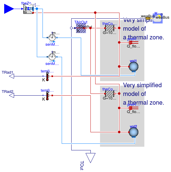
Information
This model extends Buildings.Fluid.FMI.ExportContainers.Examples.FMUs.ThermalZones to implement two simple thermal zones.
Extends from Buildings.Fluid.FMI.ExportContainers.Examples.FMUs.ThermalZones (Declaration of an FMU that exports multiple thermal zones).
Parameters
| Type | Name | Default | Description |
|---|---|---|---|
| Integer | nZon | 2 | Number of thermal zones in this container |
| Integer | nPorts | 3 | Number of fluid ports for each zone (must be the same for every zone) |
| replaceable package MediumA | Air | Medium for air | |
| Volume | V | 6*10*3 | Room volume [m3] |
| Temperature | TASup_nominal | 273.15 + 18 | Nominal air temperature supplied to room [K] |
| Temperature | TRooSet | 273.15 + 24 | Nominal room air temperature [K] |
| Temperature | TOut_nominal | 273.15 + 30 | Design outlet air temperature [K] |
| HeatFlowRate | QRooInt_flow | 1000 | Internal heat gains of the room [W] |
| HeatFlowRate | QRooC_flow_nominal | -QRooInt_flow - 10E3/30*(TOu... | Nominal cooling load of the room [W] |
| MassFlowRate | mA_flow_nominal | 1.3*QRooC_flow_nominal/1006/... | Nominal air mass flow rate, increased by factor 1.3 to allow for recovery after temperature setback [kg/s] |
Connectors
| Type | Name | Description |
|---|---|---|
| Inlet | fluPor[nZon, nPorts] | Fluid connectors |
| Bus | weaBus | Weather data bus |
| output RealOutput | TOut | Outdoor temperature [K] |
| output RealOutput | TRad1 | Radiative temperature [K] |
| output RealOutput | TRad2 | Radiative temperature [K] |