Buildings.Electrical.AC.OnePhase.Sources
Package with sources models for one phase AC systems
Information
This package contains models of AC sources.
Extends from Modelica.Icons.SourcesPackage (Icon for packages containing sources).
Package Content
| Name | Description |
|---|---|
| Fixed single phase AC voltage source | |
| Model of a generator | |
| Electrical grid | |
| Simple PV model | |
| Simple PV model with orientation | |
| Simple wind turbine model | |
| Package with example models |
 Buildings.Electrical.AC.OnePhase.Sources.FixedVoltage
Fixed single phase AC voltage source

Information
This is a constant voltage source. The complex voltage is specified by the RMS voltage and the phase shift.
Extends from Buildings.Electrical.Interfaces.Source (Partial model of a generic source.).
Parameters
| Type | Name | Default | Description |
|---|---|---|---|
| replaceable package PhaseSystem | OnePhase | Phase system | |
| Frequency | f | Frequency of the source [Hz] | |
| Voltage | V | RMS voltage of the source [V] | |
| Angle | phiSou | 0 | Phase shift of the source [rad] |
| Reference Parameters | |||
| Boolean | potentialReference | true | Serve as potential root for the reference angle theta |
| Boolean | definiteReference | false | Serve as definite root for the reference angle theta |
Connectors
| Type | Name | Description |
|---|---|---|
| replaceable package PhaseSystem | Phase system | |
Modelica definition
 Buildings.Electrical.AC.OnePhase.Sources.Generator
Model of a generator

Information
Model of a generator that produces real power
P with a given phase shift phiGen.
This model must be used with Buildings.Electrical.AC.OnePhase.Sources.Grid or with a voltage source from the package Modelica.Electrical.QuasiStationary.SinglePhase.Sources. Otherwise, there will be no equation that defines the phase angle of the voltage.
The boolean flags potentialReference and
definiteReference allows to select the phase angle of the
generator as reference for the models connected to it. More info about
these flags are available in
Buildings.Electrical.AC.UsersGuide.
Extends from Buildings.Electrical.Interfaces.Source (Partial model of a generic source.).
Parameters
| Type | Name | Default | Description |
|---|---|---|---|
| replaceable package PhaseSystem | OnePhase | Phase system | |
| Frequency | f | Frequency of the source [Hz] | |
| Angle | phiGen | 0 | Phase shift of the source [rad] |
| Reference Parameters | |||
| Boolean | potentialReference | true | Serve as potential root for the reference angle theta |
| Boolean | definiteReference | false | Serve as definite root for the reference angle theta |
Connectors
| Type | Name | Description |
|---|---|---|
| replaceable package PhaseSystem | Phase system | |
| input RealInput | P | Variable power generated by the source |
Modelica definition
 Buildings.Electrical.AC.OnePhase.Sources.Grid
Electrical grid
Information
Model that can be used to represent the electrical grid supply.
The model has an output connector named P that
contains information about the power supplied by the grid to the network.
The convention is that P.real is positive if real power is
consumed from the grid, and negative if it is fed into the grid.
The parameter V is the root means square of the voltage.
In US households, this is 120 Volts at 60 Hz,
in Europe it is 230 Volts at 50 Hz.
Parameters
| Type | Name | Default | Description |
|---|---|---|---|
| Terminal_p | terminal | redeclare Buildings.Electric... | |
| Frequency | f | Frequency of the source [Hz] | |
| Voltage | V | RMS voltage of the source [V] | |
| Angle | phiSou | 0 | Phase shift angle of the source [rad] |
| FixedVoltage | sou | redeclare Buildings.Electric... | Voltage source |
Connectors
| Type | Name | Description |
|---|---|---|
| Terminal_p | terminal | |
| PowerOutput | P | Power consumed from grid if positive, or fed to grid if negative |
Modelica definition
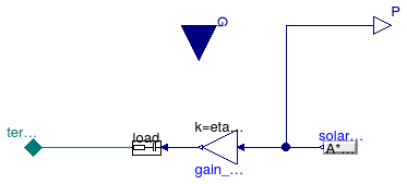
 Buildings.Electrical.AC.OnePhase.Sources.PVSimple
Simple PV model
Information
Model of a simple photovoltaic array.
The electrical connector is an AC interface.
This model computes the active power as
P=A fact η G ηDCAC,
where A is the panel area, fact is the fraction of the aperture area, η is the panel efficiency, G is the total solar irradiation, which is the sum of direct and diffuse irradiation, and ηDCAC is the efficiency of the conversion between DC and AC.
This active power is equal to P, while the reactive power is equal to Q = P tan(acos(pf)) where pf is the power factor.
Note: This model takes as input the total solar irradiation on the panel. This has to be computed converting the incoming radiation to take tilt and azimuth into account. For a model that implements this conversion, use Buildings.Electrical.AC.OnePhase.Sources.PVSimpleOriented.
Extends from Buildings.Electrical.Interfaces.PartialAcDcParameters (Partial model that contains basic parameters for a DC/AC conversion system), Buildings.Electrical.Interfaces.PartialPV (Base model for a PV system).
Parameters
| Type | Name | Default | Description |
|---|---|---|---|
| Area | A | Net surface area [m2] | |
| Real | fAct | 0.9 | Fraction of surface area with active solar cells [1] |
| Real | eta | 0.12 | Module conversion efficiency [1] |
| replaceable package PhaseSystem | PartialPhaseSystem | Phase system | |
| Boolean | linearized | false | If =true, introduce a linearization in the load |
| Capacitive | load | redeclare Buildings.Electric... | Load model |
| AC-Conversion | |||
| Real | pf | 0.9 | Power factor |
| Real | eta_DCAC | 0.9 | Efficiency of DC/AC conversion |
Connectors
| Type | Name | Description |
|---|---|---|
| output RealOutput | P | Generated power [W] |
| replaceable package PhaseSystem | Phase system | |
| input RealInput | G | Total solar irradiation per unit area [W/m2] |
Modelica definition
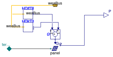
 Buildings.Electrical.AC.OnePhase.Sources.PVSimpleOriented
Simple PV model with orientation
Information
Model of a simple photovoltaic array.
This model takes as an input the direct and diffuse solar radiation from the weather bus. The electrical connector is an AC one phase interface.
This model computes the active power as
P=A fact η G ηDCAC,
where A is the panel area, fact is the fraction of the aperture area, η is the panel efficiency, G is the total solar irradiation, which is the sum of direct and diffuse irradiation, and ηDCAC is the efficiency of the conversion between DC and AC. The model takes into account the location and the orientation of the PV panel, specified by the surface tilt, latitude and azimuth.
This active power is equal to P, while the reactive power is equal to Q = P tan(acos(pf)), where pf is the power factor.
Extends from Buildings.Electrical.Interfaces.PartialAcDcParameters (Partial model that contains basic parameters for a DC/AC conversion system), Buildings.Electrical.Interfaces.PartialPVOriented (Base model of a PV system with orientation).
Parameters
| Type | Name | Default | Description |
|---|---|---|---|
| Area | A | Net surface area [m2] | |
| Real | fAct | 0.9 | Fraction of surface area with active solar cells [1] |
| Real | eta | 0.12 | Module conversion efficiency [1] |
| replaceable package PhaseSystem | PartialPhaseSystem | Phase system | |
| Boolean | linearized | false | If =true, linearize the load |
| AC-Conversion | |||
| Real | pf | 0.9 | Power factor |
| Real | eta_DCAC | 0.9 | Efficiency of DC/AC conversion |
| Orientation | |||
| Angle | til | Surface tilt [rad] | |
| Angle | lat | Latitude [rad] | |
| Angle | azi | Surface azimuth [rad] | |
Connectors
| Type | Name | Description |
|---|---|---|
| output RealOutput | P | Generated power [W] |
| replaceable package PhaseSystem | Phase system | |
| Bus | weaBus | Weather data |
Modelica definition
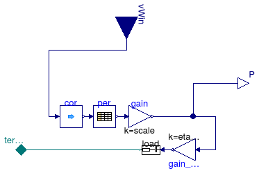
 Buildings.Electrical.AC.OnePhase.Sources.WindTurbine
Simple wind turbine model
Information
Model of a wind turbine whose power is computed as a function of wind-speed as defined in a table.
Input to the model is the local wind speed.
The model requires the specification of a table that maps wind speed in meters per second to generated
power Pt in Watts.
The model has a parameter called scale with a default value of one
that can be used to scale the power generated by the wind turbine.
The generated active electrical power is
P = Pt scale ηDCAC
where ηDCAC is the efficiency of the conversion of the DC electrical power to AC.
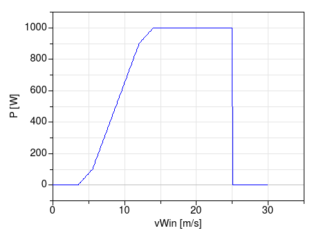
For example, the following specification (with default scale=1) of a wind turbine
  WindTurbine_Table tur(
    table=[3.5, 0;
           5.5,   100;
           12, 900;
           14, 1000;
           25, 1000]) "Wind turbine";
yields the performance shown below. In this example, the cut-in wind speed is 3.5 meters per second, and the cut-out wind speed is 25 meters per second, as entered by the first and last entry of the wind speed column. Below and above these wind speeds, the generated power is zero.
Extends from Buildings.Electrical.Interfaces.PartialWindTurbine (Partial model of a wind turbine with power output based on table as a function of wind speed).
Parameters
| Type | Name | Default | Description |
|---|---|---|---|
| Real | scale | 1 | Scaling factor, used to allow adjusting the power output without changing the table |
| Boolean | tableOnFile | false | true, if table is defined on file or in function usertab |
| Real | table[:, 2] | [3.5, 0; 5.5, 0.1; 12, 0.9; ... | Table of generated power (first column is wind speed, second column is power) |
| String | tableName | "NoName" | Table name on file or in function usertab (see documentation) |
| String | fileName | "NoName" | File where matrix is stored |
| replaceable package PhaseSystem | PartialPhaseSystem | Phase system | |
| Capacitive | load | redeclare Buildings.Electric... | Load model |
| Wind correction | |||
| Real | h | Height over ground | |
| Height | hRef | 10 | Reference height for wind measurement [m] |
| Real | nWin | 0.4 | Height exponent for wind profile calculation |
| AC-Conversion | |||
| Real | pf | 0.9 | Power factor |
| Real | eta_DCAC | 0.9 | Efficiency of DC/AC conversion |
Connectors
| Type | Name | Description |
|---|---|---|
| input RealInput | vWin | Steady wind speed [m/s] |
| output RealOutput | P | Generated power [W] |
| replaceable package PhaseSystem | Phase system | |