Collection of validation models
Information
This package contains validation models for the classes in
Buildings.Controls.OBC.ASHRAE.G36_PR1.AHUs.MultiZone.SetPoints.
Note that most validation models contain simple input data
which may not be realistic, but for which the correct
output can be obtained through an analytic solution.
The examples plot various outputs, which have been verified against these
solutions. These model outputs are stored as reference data and
used for continuous validation whenever models in the library change.
Package Content
| Name |
Description |
 ExhaustDamper ExhaustDamper
|
Validate the controller of an actuated exhaust damper without fan |
| OutsideAirFlow
|
Validate the model of calculating minimum outdoor airflow setpoint |
| ReturnFanDirectPressure
|
Validate model for calculating return fan control with direct building pressure
of multi zone VAV AHU |
| VAVSupplyFan
|
Validate VAVSupplyFan |
| VAVSupplyTemperature
|
Validate model for calculating supply air temperature of multi zone VAV AHU |
| Valve
|
Validate model for controlling coil valve postion of multi zone VAV AHU |
Validate the controller of an actuated exhaust damper without fan
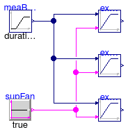
Information
This example validates
Buildings.Controls.OBC.ASHRAE.G36_PR1.AHUs.MultiZone.SetPoints.ExhaustDamper.
Modelica definition
Validate the model of calculating minimum outdoor airflow setpoint
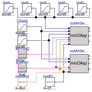
Information
This example validates
Buildings.Controls.OBC.ASHRAE.G36_PR1.AHUs.MultiZone.SetPoints.OutsideAirFlow.
Parameters
| Type | Name | Default | Description |
|---|
| Integer | numZon | 5 | Total number of zones that the system serves |
Modelica definition
model OutsideAirFlow
parameter Integer numZon = 5 ;
Buildings.Controls.OBC.ASHRAE.G36_PR1.AHUs.MultiZone.SetPoints.OutsideAirFlow
outAirSet_MulZon(numZon=numZon,
AFlo=
fill(40, numZon),
maxSysPriFlo=1,
minZonPriFlo=
fill(0.08, numZon),
peaSysPop=20)
;
Buildings.Controls.OBC.ASHRAE.G36_PR1.AHUs.MultiZone.SetPoints.OutsideAirFlow
outAirSet_MulZon1(
numZon=numZon,
AFlo=
fill(40, numZon),
maxSysPriFlo=1,
minZonPriFlo=
fill(0.08, numZon),
peaSysPop=20,
have_occSen=false,
have_winSen=false)
;
Buildings.Controls.OBC.CDL.Continuous.Sources.Constant zonPriFloRat[numZon](
k={0.1,0.12,0.2,0.09,0.1})
;
Buildings.Controls.OBC.CDL.Continuous.Sources.Ramp numOfOcc1(
height=2,
duration=3600)
;
Buildings.Controls.OBC.CDL.Continuous.Sources.Ramp numOfOcc2(
duration=3600,
height=3)
;
Buildings.Controls.OBC.CDL.Continuous.Sources.Ramp numOfOcc3(
duration=3600,
height=3,
startTime=900) ;
Buildings.Controls.OBC.CDL.Continuous.Sources.Ramp numOfOcc4(
duration=3600,
startTime=900,
height=2) ;
Buildings.Controls.OBC.CDL.Continuous.Sources.Ramp numOfOcc5(
duration=3600,
startTime=0,
height=-3,
offset=3) ;
protected
Buildings.Controls.OBC.CDL.Logical.Sources.Constant winSta[numZon](
k=
fill(false,numZon))
;
Buildings.Controls.OBC.CDL.Logical.Sources.Constant supFan(
k=true) ;
Buildings.Controls.OBC.CDL.Continuous.Sources.Ramp TZon[numZon](
each height=6,
each offset=273.15 + 17,
each duration=3600) ;
Buildings.Controls.OBC.CDL.Continuous.Sources.Ramp TDis[numZon](
each height=4,
each duration=3600,
each offset=273.15 + 18) ;
Buildings.Controls.OBC.CDL.Integers.Sources.Constant opeMod(
final k=Buildings.Controls.OBC.ASHRAE.G36_PR1.Types.OperationModes.occupied)
;
equation
connect(winSta.y, outAirSet_MulZon.uWin);
connect(supFan.y, outAirSet_MulZon.uSupFan);
connect(zonPriFloRat.y, outAirSet_MulZon.VBox_flow);
connect(TZon.y, outAirSet_MulZon.TZon);
connect(TDis.y,outAirSet_MulZon.TDis);
connect(numOfOcc1.y, outAirSet_MulZon.nOcc[1]);
connect(numOfOcc2.y, outAirSet_MulZon.nOcc[2]);
connect(numOfOcc3.y, outAirSet_MulZon.nOcc[3]);
connect(numOfOcc4.y, outAirSet_MulZon.nOcc[4]);
connect(numOfOcc5.y, outAirSet_MulZon.nOcc[5]);
connect(opeMod.y, outAirSet_MulZon.uOpeMod);
connect(zonPriFloRat.y, outAirSet_MulZon1.VBox_flow);
connect(opeMod.y, outAirSet_MulZon1.uOpeMod);
connect(supFan.y, outAirSet_MulZon1.uSupFan);
connect(TDis.y, outAirSet_MulZon1.TDis);
connect(TZon.y, outAirSet_MulZon1.TZon);
end OutsideAirFlow;
Validate model for calculating return fan control with direct building pressure
of multi zone VAV AHU
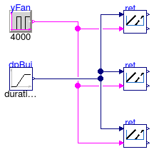
Information
This example validates
Buildings.Controls.OBC.ASHRAE.G36_PR1.AHUs.MultiZone.SetPoints.ReturnFanDirectPressure
for exhaust air damper and return fan control with direct building pressure measurement
for systems with multiple
zones.
Modelica definition
Validate VAVSupplyFan

Information
This example validates
Buildings.Controls.OBC.ASHRAE.G36_PR1.AHUs.MultiZone.SetPoints.VAVSupplyFan.
Modelica definition
model VAVSupplyFan
Buildings.Controls.OBC.ASHRAE.G36_PR1.AHUs.MultiZone.SetPoints.VAVSupplyFan
conSupFan(numZon=4,
Td=1,
controllerType=Buildings.Controls.OBC.CDL.Types.SimpleController.PI,
maxSet=400,
k=0.001,
Ti=10) ;
Buildings.Controls.OBC.CDL.Continuous.Sources.Ramp ram(
duration=28800,
height=6) ;
Buildings.Controls.OBC.CDL.Continuous.Sources.Ramp vavBoxFlo1(
duration=28800,
height=1.5,
offset=1) ;
Buildings.Controls.OBC.CDL.Continuous.Sources.Ramp vavBoxFlo2(
duration=28800,
offset=1,
height=0.5) ;
Buildings.Controls.OBC.CDL.Continuous.Sources.Ramp vavBoxFlo3(
duration=28800,
height=1,
offset=0.3) ;
Buildings.Controls.OBC.CDL.Continuous.Sources.Ramp vavBoxFlo4(
duration=28800,
height=1,
offset=0) ;
Buildings.Controls.OBC.CDL.Continuous.Sources.Sine sine(
freqHz=1/14400,
offset=3,
amplitude=2) ;
Buildings.Controls.OBC.CDL.Continuous.Sources.Sine sine1(
freqHz=1/14400,
offset=200,
amplitude=150) ;
Buildings.Controls.OBC.CDL.Continuous.Abs abs
;
Buildings.Controls.OBC.CDL.Continuous.Abs abs1
;
Buildings.Controls.OBC.CDL.Continuous.Round round2(n=0)
;
Buildings.Controls.OBC.CDL.Conversions.RealToInteger reaToInt1
;
Buildings.Controls.OBC.CDL.Conversions.RealToInteger reaToInt2
;
Buildings.Controls.OBC.CDL.Continuous.Round round1(n=0)
;
equation
connect(vavBoxFlo1.y, conSupFan.VBox_flow[1]);
connect(vavBoxFlo2.y, conSupFan.VBox_flow[2]);
connect(vavBoxFlo3.y, conSupFan.VBox_flow[3]);
connect(vavBoxFlo4.y, conSupFan.VBox_flow[4]);
connect(sine1.y, conSupFan.ducStaPre);
connect(sine.y, abs1.u);
connect(ram.y, abs.u);
connect(abs1.y, round2.u);
connect(round2.y, reaToInt1.u);
connect(reaToInt1.y, conSupFan.uZonPreResReq);
connect(abs.y, round1.u);
connect(round1.y, reaToInt2.u);
connect(reaToInt2.y, conSupFan.uOpeMod);
end VAVSupplyFan;
Validate model for calculating supply air temperature of multi zone VAV AHU
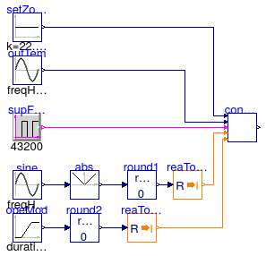
Information
This example validates
Buildings.Controls.OBC.ASHRAE.G36_PR1.AHUs.MultiZone.SetPoints.VAVSupplyTemperature
for a change of outdoor temperature, operation mode, supply fan status, maximum
supply temperature, to specify the supply air temperature for systems with multiple
zones.
Modelica definition
model VAVSupplyTemperature
Buildings.Controls.OBC.ASHRAE.G36_PR1.AHUs.MultiZone.SetPoints.VAVSupplyTemperature
conTSetSup
;
Buildings.Controls.OBC.CDL.Continuous.Sources.Constant setZonTem(
k=22.5 + 273.15) ;
Buildings.Controls.OBC.CDL.Continuous.Sources.Sine outTem(
amplitude=5,
freqHz=1/86400,
offset=18 + 273.15) ;
Buildings.Controls.OBC.CDL.Logical.Sources.Pulse supFanSta(period=43200)
;
Buildings.Controls.OBC.CDL.Continuous.Sources.Ramp opeMod(
offset=1,
height=1,
duration=90000) ;
Buildings.Controls.OBC.CDL.Continuous.Abs abs
;
Buildings.Controls.OBC.CDL.Continuous.Sources.Sine sine(
amplitude=6, freqHz=1/86400)
;
Buildings.Controls.OBC.CDL.Conversions.RealToInteger reaToInt1
;
Buildings.Controls.OBC.CDL.Continuous.Round round1(n=0)
;
Buildings.Controls.OBC.CDL.Conversions.RealToInteger reaToInt2
;
Buildings.Controls.OBC.CDL.Continuous.Round round2(n=0)
;
equation
connect(supFanSta.y, conTSetSup.uSupFan);
connect(outTem.y, conTSetSup.TOut);
connect(setZonTem.y, conTSetSup.TSetZones);
connect(sine.y, abs.u);
connect(opeMod.y, round2.u);
connect(round2.y, reaToInt2.u);
connect(abs.y, round1.u);
connect(round1.y, reaToInt1.u);
connect(reaToInt1.y, conTSetSup.uZonTemResReq);
connect(reaToInt2.y, conTSetSup.uOpeMod);
end VAVSupplyTemperature;
Validate model for controlling coil valve postion of multi zone VAV AHU
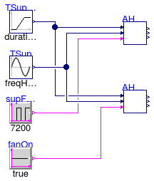
Information
This example validates
Buildings.Controls.OBC.ASHRAE.G36_PR1.AHUs.MultiZone.SetPoints.VAVSupplySignals
for a change of the supply air temperature setpoint, measured supply air temperature and
the supply fan status, to specify coil valve positions, and generate control
loop signal.
Modelica definition
model Valve
Buildings.Controls.OBC.ASHRAE.G36_PR1.AHUs.MultiZone.SetPoints.VAVSupplySignals
AHUValve
;
Buildings.Controls.OBC.CDL.Logical.Sources.Pulse supFanSta(period=7200)
;
Buildings.Controls.OBC.CDL.Continuous.Sources.Sine TSup(
amplitude=2,
offset=16 + 273.15,
freqHz=1/7200) ;
Buildings.Controls.OBC.CDL.Continuous.Sources.Ramp TSupSet(
height=3,
duration=7200,
offset=15 + 273.15)
;
Buildings.Controls.OBC.ASHRAE.G36_PR1.AHUs.MultiZone.SetPoints.VAVSupplySignals
AHUValve1
;
Buildings.Controls.OBC.CDL.Logical.Sources.Constant fanOn(k=true) ;
equation
connect(TSupSet.y, AHUValve.TSetSup);
connect(TSup.y, AHUValve.TSup);
connect(supFanSta.y, AHUValve.uSupFan);
connect(TSupSet.y, AHUValve1.TSetSup);
connect(TSup.y, AHUValve1.TSup);
connect(fanOn.y, AHUValve1.uSupFan);
end Valve;
 Buildings.Controls.OBC.ASHRAE.G36_PR1.AHUs.MultiZone.SetPoints.Validation.ExhaustDamper