Buildings.Controls.OBC.CDL.Continuous
Package with elementary mathematical functions for continuous variables
Information
Package with blocks for elementary mathematical functions for continuous variables.
Extends from Modelica.Icons.Package (Icon for standard packages).
Package Content
| Name | Description |
|---|---|
| Output the absolute value of the input | |
| Output the sum of the two inputs | |
| Output the sum of an input plus a parameter | |
| Output the arc tangent of the input | |
| Output atan(u1/u2) of the inputs u1 and u2 | |
| Output the average of its two inputs | |
| Change sign of the input | |
| Output the cosine of the input | |
| Block that approximates the derivative of the input | |
| Output first input divided by second input | |
| Output the exponential (base e) of the input | |
| Output difference between commanded and feedback input | |
| Output the product of a gain value with the input signal | |
| Output y is true, if input u1 is greater than input u2 | |
| Output y is true, if input u1 is greater or equal than input u2 | |
| Output y is true, if input u is greater or equal than threshold | |
| Output y is true, if input u is greater than threshold | |
| Transform Real to Boolean signal with Hysteresis | |
| Hysteresis block that optionally allows to specify a hold time | |
| Output the integral of the input signal | |
| Output y is true, if input u1 is less than input u2 | |
| Output y is true, if input u1 is less or equal than input u2 | |
| Output y is true, if input u is less or equal than threshold | |
| Output y is true, if input u is less than threshold | |
| P, PI, PD, and PID controller with limited output, anti-windup compensation and setpoint weighting | |
| Limit the range of a signal | |
| Output the value of the input x along a line specified by two points | |
| Output the natural (base e) logarithm of the input (input > 0 required) | |
| Output the base 10 logarithm of the input (input > 0 required) | |
| Pass through the largest signal | |
| Pass through the smallest signal | |
| Output the remainder of first input divided by second input (~=0) | |
| Block to output moving average | |
| Output the maximum element of the input vector | |
| Output the minimum element of the input vector | |
| Sum of Reals, y = k[1]*u[1] + k[2]*u[2] + ... + k[n]*u[n] | |
| Outputs the number of signals that are above/below a certain threshold | |
| Output product of the two inputs | |
| Round real number to given digits | |
| Output the sine of the input | |
| Limit the increase or decrease rate of input | |
| Sort elements of input vector in ascending or descending order | |
| Output the square root of the input (input >= 0 required) | |
| Output the tangent of the input | |
| Package with blocks that generate source signals | |
| Collection of models that validate the continuous blocks of the CDL |
 Buildings.Controls.OBC.CDL.Continuous.Abs
Output the absolute value of the input

Information
Block that outputs y = abs(u),
where
u is an input.
Connectors
| Type | Name | Description |
|---|---|---|
| input RealInput | u | Connector of Real input signal |
| output RealOutput | y | Connector of Real output signal |
Modelica definition
 Buildings.Controls.OBC.CDL.Continuous.Add
Output the sum of the two inputs

Information
Block that outputs y as the weighted sum of the
two input signals u1 and u2,
y = k1*u1 + k2*u2;
where k1 and k2 are parameters.
Parameters
| Type | Name | Default | Description |
|---|---|---|---|
| Real | k1 | +1 | Gain for input u1 |
| Real | k2 | +1 | Gain for input u2 |
Connectors
| Type | Name | Description |
|---|---|---|
| input RealInput | u1 | Connector of Real input signal 1 |
| input RealInput | u2 | Connector of Real input signal 2 |
| output RealOutput | y | Connector of Real output signal |
Modelica definition
 Buildings.Controls.OBC.CDL.Continuous.AddParameter
Output the sum of an input plus a parameter
Information
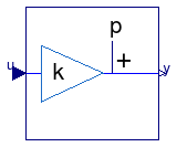
Block that outputs y = k u + p,
where k and p are
parameters and u is an input.
Parameters
| Type | Name | Default | Description |
|---|---|---|---|
| Real | p | Value to be added | |
| Real | k | Gain of input |
Connectors
| Type | Name | Description |
|---|---|---|
| input RealInput | u | Connector of Real input signal |
| output RealOutput | y | Connector of Real output signal |
Modelica definition
 Buildings.Controls.OBC.CDL.Continuous.Atan
Output the arc tangent of the input

Information
Block that outputs y = atan(u),
where
u is an input.
Connectors
| Type | Name | Description |
|---|---|---|
| input RealInput | u | Connector of Real input signal |
| output RealOutput | y | Connector of Real output signal |
Modelica definition
 Buildings.Controls.OBC.CDL.Continuous.Atan2
Output atan(u1/u2) of the inputs u1 and u2

Information
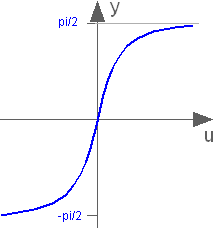
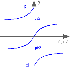
Block that outputs the tangent-inverse y = atan2(u1, u2)
of the input u1 divided by the input u2.
u1 and u2 shall not be zero at the same time instant.
Atan2 uses the sign of u1 and u2
in order to construct the solution in the range
-π ≤ y ≤ π, whereas
Buildings.Controls.OBC.CDL.Continuous.Atan
gives a solution in the range
-π/2 ≤ y ≤ π/2.
Connectors
| Type | Name | Description |
|---|---|---|
| input RealInput | u1 | Connector of Real input signal 1 |
| input RealInput | u2 | Connector of Real input signal 2 |
| output RealOutput | y | Connector of Real output signal |
Modelica definition
 Buildings.Controls.OBC.CDL.Continuous.Average
Output the average of its two inputs
Information
Block that outputs y = avg(u1,u2),
where
u1 and u2 are inputs.
Connectors
| Type | Name | Description |
|---|---|---|
| input RealInput | u1 | Connector of Real input signal 1 |
| input RealInput | u2 | Connector of Real input signal 2 |
| output RealOutput | y | Connector of Real output signal |
Modelica definition
 Buildings.Controls.OBC.CDL.Continuous.ChangeSign
Change sign of the input

Information
Block that outputs y = -u,
where u is an input.
Connectors
| Type | Name | Description |
|---|---|---|
| input RealInput | u | Connector of Real input signal |
| output RealOutput | y | Connector of Real output signal |
Modelica definition
 Buildings.Controls.OBC.CDL.Continuous.Cos
Output the cosine of the input
Information
Block that outputs y = cos(u),
where
u is an input.
Connectors
| Type | Name | Description |
|---|---|---|
| input RealInput | u | Connector of Real input signal |
| output RealOutput | y | Connector of Real output signal |
Modelica definition
 Buildings.Controls.OBC.CDL.Continuous.Derivative
Block that approximates the derivative of the input
Information
This blocks defines the transfer function between the
input u and the output y
(element-wise) as approximated derivative:
             k * s
     y = ------------ * u
            T * s + 1
If k=0, the block reduces to y=0.
Parameters
| Type | Name | Default | Description |
|---|---|---|---|
| Real | k | 1 | Gains [1] |
| Time | T | 0.01 | Time constant (T>0 required) [s] |
| Initialization | |||
| Init | initType | Buildings.Controls.OBC.CDL.T... | Type of initialization (1: no init, 2: initial state, 3: initial output) |
| Real | x_start | 0 | Initial or guess value of state |
| Real | y_start | 0 | Initial value of output (= state) |
Connectors
| Type | Name | Description |
|---|---|---|
| input RealInput | u | Connector of Real input signal |
| output RealOutput | y | Connector of Real output signal |
Modelica definition
 Buildings.Controls.OBC.CDL.Continuous.Division
Output first input divided by second input

Information
Block that outputs y = u1 / u2,
where
u1 and u2 are inputs.
Connectors
| Type | Name | Description |
|---|---|---|
| input RealInput | u1 | Connector of Real input signal 1 |
| input RealInput | u2 | Connector of Real input signal 2 |
| output RealOutput | y | Connector of Real output signal |
Modelica definition
 Buildings.Controls.OBC.CDL.Continuous.Exp
Output the exponential (base e) of the input

Information
Block that outputs y = exp(u),
where
u is an input and exp() is the
base-e exponential function.
Connectors
| Type | Name | Description |
|---|---|---|
| input RealInput | u | Connector of Real input signal |
| output RealOutput | y | Connector of Real output signal |
Modelica definition
 Buildings.Controls.OBC.CDL.Continuous.Feedback
Output difference between commanded and feedback input
Information
Block that outputs y = u1 - u2,
where
u1 and u2 are inputs.
Connectors
| Type | Name | Description |
|---|---|---|
| input RealInput | u1 | Connector of Real input signal 1 |
| input RealInput | u2 | Connector of Real input signal 2 |
| output RealOutput | y | Connector of Real output signal |
Modelica definition
 Buildings.Controls.OBC.CDL.Continuous.Gain
Output the product of a gain value with the input signal

Information
Block that outputs y = k * u,
where
k is a parameter and
u is an input.
Parameters
| Type | Name | Default | Description |
|---|---|---|---|
| Real | k | Gain value multiplied with input signal |
Connectors
| Type | Name | Description |
|---|---|---|
| input RealInput | u | Input signal connector |
| output RealOutput | y | Output signal connector |
Modelica definition
 Buildings.Controls.OBC.CDL.Continuous.Greater
Output y is true, if input u1 is greater than input u2
Information
Block that outputs true if the Real input u1
is greater than the Real input u2.
Otherwise the output is false.
Connectors
| Type | Name | Description |
|---|---|---|
| input RealInput | u1 | Connector of first Real input signal |
| input RealInput | u2 | Connector of second Real input signal |
| output BooleanOutput | y | Connector of Boolean output signal |
Modelica definition
 Buildings.Controls.OBC.CDL.Continuous.GreaterEqual
Output y is true, if input u1 is greater or equal than input u2
Information
Block that outputs true if Real the input u1
is greater than or equal to the Real input u2.
Otherwise the output is false.
Connectors
| Type | Name | Description |
|---|---|---|
| input RealInput | u1 | Connector of first Real input signal |
| input RealInput | u2 | Connector of second Real input signal |
| output BooleanOutput | y | Connector of Boolean output signal |
Modelica definition
 Buildings.Controls.OBC.CDL.Continuous.GreaterEqualThreshold
Output y is true, if input u is greater or equal than threshold

Information
Block that outputs true if the Real input is greater than or equal to
the parameter threshold.
Otherwise the output is false.
Parameters
| Type | Name | Default | Description |
|---|---|---|---|
| Real | threshold | 0 | Comparison with respect to threshold |
Connectors
| Type | Name | Description |
|---|---|---|
| input RealInput | u | Connector of Real input signal |
| output BooleanOutput | y | Connector of Boolean output signal |
Modelica definition
 Buildings.Controls.OBC.CDL.Continuous.GreaterThreshold
Output y is true, if input u is greater than threshold
Information
Block that outputs true if the Real input is greater than
the parameter threshold.
Otherwise the output is false.
Parameters
| Type | Name | Default | Description |
|---|---|---|---|
| Real | threshold | 0 | Comparison with respect to threshold |
Connectors
| Type | Name | Description |
|---|---|---|
| input RealInput | u | Connector of Real input signal |
| output BooleanOutput | y | Connector of Boolean output signal |
Modelica definition
 Buildings.Controls.OBC.CDL.Continuous.Hysteresis
Transform Real to Boolean signal with Hysteresis
Information
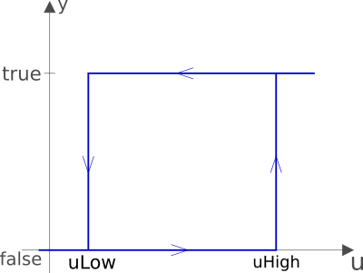
Block that transforms a Real input signal into a Boolean
output signal:
- When the output was
falseand the input becomes greater than the parameteruHigh, the output switches totrue. - When the output was
trueand the input becomes less than the parameteruLow, the output switches tofalse.
The start value of the output is defined via parameter
pre_y_start (= value of pre(y) at initial time).
The default value of this parameter is false.
Parameters
| Type | Name | Default | Description |
|---|---|---|---|
| Real | uLow | if y=true and u<=uLow, switch to y=false | |
| Real | uHigh | if y=false and u>=uHigh, switch to y=true | |
| Boolean | pre_y_start | false | Value of pre(y) at initial time |
Connectors
| Type | Name | Description |
|---|---|---|
| input RealInput | u | Real input signal |
| output BooleanOutput | y | Boolean output signal |
Modelica definition
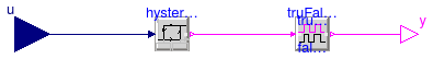
 Buildings.Controls.OBC.CDL.Continuous.HysteresisWithHold
Hysteresis block that optionally allows to specify a hold time
Information
Model for a hysteresis block that optionally allows to specify a hold time. During the hold time, the output is not allowed to switch.
When the input u becomes greater than uHigh, the
output y becomes true and remains true
for at least trueHoldDuration seconds, after which time it is allowed
to switch immediately.
When the input u becomes less than uLow, the output
y becomes false and remains false for
at least falseHoldDuration seconds, after which time it is allowed
to switch immediately.
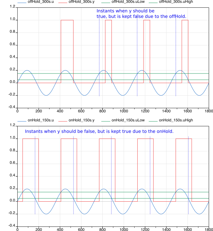
This model for example could be used to disable an economizer, and not re-enable it for 10 minutes, and vice versa. Using hysteresis can avoid the distraction from the input noise.
Parameters
| Type | Name | Default | Description |
|---|---|---|---|
| Real | uLow | if y=true and u<=uLow, switch to y=false | |
| Real | uHigh | if y=false and u>=uHigh, switch to y=true | |
| Time | trueHoldDuration | true hold duration [s] | |
| Time | falseHoldDuration | trueHoldDuration | false hold duration [s] |
Connectors
| Type | Name | Description |
|---|---|---|
| input RealInput | u | Real input signal |
| output BooleanOutput | y | Boolean output signal |
Modelica definition
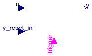
 Buildings.Controls.OBC.CDL.Continuous.IntegratorWithReset
Output the integral of the input signal
Information
This model is similar to
Modelica.Blocks.Continuous.Integrator
except that it optionally allows to reset the output y
of the integrator.
The output of the integrator can be reset as follows:
-
If
reset = Types.Reset.Disabled, which is the default, then the integrator is never reset. -
If
reset = Types.Reset.Parameter, then a boolean input signaltriggeris enabled. Whenever the value of this input changes fromfalsetotrue, the integrator is reset by settingyto the value of the parametery_reset. -
If
reset = Types.Reset.Input, then a boolean input signaltriggeris enabled. Whenever the value of this input changes fromfalsetotrue, the integrator is reset by settingyto the value of the input signaly_reset_in.
Implementation
To adjust the icon layer, the code of Modelica.Blocks.Continuous.Integrator has been copied into this model rather than extended.
Parameters
| Type | Name | Default | Description |
|---|---|---|---|
| Real | k | 1 | Integrator gain [1] |
| Reset | reset | Buildings.Controls.OBC.CDL.T... | Type of integrator reset |
| Initialization | |||
| Init | initType | Buildings.Controls.OBC.CDL.T... | Type of initialization (1: no init, 2: initial state, 3: initial output) |
| Real | y_start | 0 | Initial or guess value of output (= state) |
| Integrator reset | |||
| Real | y_reset | 0 | Value to which integrator is reset, used if reset = Types.Reset.Parameter |
Connectors
| Type | Name | Description |
|---|---|---|
| input RealInput | u | Connector of Real input signal |
| output RealOutput | y | Connector of Real output signal |
| input RealInput | y_reset_in | Input signal for state to which integrator is reset, enabled if reset = Types.Reset.Input |
| input BooleanInput | trigger | Resets the integrator output when trigger becomes true |
Modelica definition
 Buildings.Controls.OBC.CDL.Continuous.Less
Output y is true, if input u1 is less than input u2

Information
Block that outputs true if the Real input u1
is less than the Real input u2.
Otherwise the output is false.
Connectors
| Type | Name | Description |
|---|---|---|
| input RealInput | u1 | Connector of first Real input signal |
| input RealInput | u2 | Connector of second Real input signal |
| output BooleanOutput | y | Connector of Boolean output signal |
Modelica definition
 Buildings.Controls.OBC.CDL.Continuous.LessEqual
Output y is true, if input u1 is less or equal than input u2
Information
Block that outputs true if the Real input u1
is less than or equal to the Real input u2.
Otherwise the output is false.
Connectors
| Type | Name | Description |
|---|---|---|
| input RealInput | u1 | Connector of first Real input signal |
| input RealInput | u2 | Connector of second Real input signal |
| output BooleanOutput | y | Connector of Boolean output signal |
Modelica definition
 Buildings.Controls.OBC.CDL.Continuous.LessEqualThreshold
Output y is true, if input u is less or equal than threshold

Information
Block that outputs true if the Real input is less than or equal to
the parameter threshold.
Otherwise the output is false.
Parameters
| Type | Name | Default | Description |
|---|---|---|---|
| Real | threshold | 0 | Comparison with respect to threshold |
Connectors
| Type | Name | Description |
|---|---|---|
| input RealInput | u | Connector of Real input signal |
| output BooleanOutput | y | Connector of Boolean output signal |
Modelica definition
 Buildings.Controls.OBC.CDL.Continuous.LessThreshold
Output y is true, if input u is less than threshold
Information
Block that outputs true if the Real input is less than
the parameter threshold.
Otherwise the output is false.
Parameters
| Type | Name | Default | Description |
|---|---|---|---|
| Real | threshold | 0 | Comparison with respect to threshold |
Connectors
| Type | Name | Description |
|---|---|---|
| input RealInput | u | Connector of Real input signal |
| output BooleanOutput | y | Connector of Boolean output signal |
Modelica definition
 Buildings.Controls.OBC.CDL.Continuous.LimPID
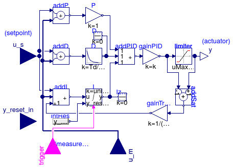
P, PI, PD, and PID controller with limited output, anti-windup compensation and setpoint weighting
Information
PID controller in the standard form
y = k ( e(t) + 1 ⁄ Ti ∫ e(s) ds + Td de(t)⁄dt ),
where y is the control signal, e(t) = us - um is the control error, with us being the set point and um being the measured quantity, k is the gain, Ti is the time constant of the integral term and Td is the time constant of the derivative term.
Note that the units of k are the inverse of the units of the control error, while the units of Ti and Td are seconds.
For detailed treatment of integrator anti-windup, set-point weights and output limitation, see Modelica.Blocks.Continuous.LimPID. The model is similar to Modelica.Blocks.Continuous.LimPID, except for the following changes:
-
It can be configured to have a reverse action.
If the parameter
reverseAction=false(the default), thenu_m < u_sincreases the controller output, otherwise the controller output is decreased. Thus,- for a heating coil with a two-way valve, set
reverseAction = false, - for a cooling coils with a two-way valve, set
reverseAction = true.
- for a heating coil with a two-way valve, set
-
It can be configured to enable an input port that allows resetting the controller output. The controller output can be reset as follows:
-
If
reset = CDL.Types.Reset.Disabled, which is the default, then the controller output is never reset. -
If
reset = CDL.Types.Reset.Parameter, then a boolean input signaltriggeris enabled. Whenever the value of this input changes fromfalsetotrue, the controller output is reset by settingyto the value of the parametery_reset. -
If
reset = CDL.Types.Reset.Input, then a boolean input signaltriggeris enabled. Whenever the value of this input changes fromfalsetotrue, the controller output is reset by settingyto the value of the input signaly_reset_in.
Note that this controller implements an integrator anti-windup. Therefore, for most applications, keeping the default setting of
reset = CDL.Types.Reset.Disabledis sufficient. Examples where it may be beneficial to reset the controller output are situations where the equipment control input should continuously increase as the equipment is switched on, such as as a light dimmer that may slowly increase the luminance, or a variable speed drive of a motor that should continuously increase the speed. -
If
-
The parameter
limitsAtInithas been removed. - Some parameters assignments in the instances have been made final.
For recommendations regarding tuning of closed loop control, see Modelica.Blocks.Continuous.LimPID or the control literature.
Parameters
| Type | Name | Default | Description |
|---|---|---|---|
| SimpleController | controllerType | Buildings.Controls.OBC.CDL.T... | Type of controller |
| Real | k | 1 | Gain of controller [1] |
| Time | Ti | 0.5 | Time constant of integrator block [s] |
| Time | Td | 0.1 | Time constant of derivative block [s] |
| Real | yMax | Upper limit of output | |
| Real | yMin | -yMax | Lower limit of output |
| Real | wp | 1 | Set-point weight for Proportional block (0..1) |
| Real | wd | 0 | Set-point weight for Derivative block (0..1) |
| Real | Ni | 0.9 | Ni*Ti is time constant of anti-windup compensation |
| Real | Nd | 10 | The higher Nd, the more ideal the derivative block |
| Boolean | reverseAction | false | Set to true for throttling the water flow rate through a cooling coil controller |
| Initialization | |||
| Init | initType | Buildings.Controls.OBC.CDL.T... | Type of initialization |
| Real | xi_start | 0 | Initial or guess value value for integrator output (= integrator state) |
| Real | xd_start | 0 | Initial or guess value for state of derivative block |
| Real | y_start | 0 | Initial value of output |
| Integrator reset | |||
| Reset | reset | Buildings.Controls.OBC.CDL.T... | Type of controller output reset |
| Real | y_reset | xi_start | Value to which the controller output is reset if the boolean trigger has a rising edge, used if reset == CDL.Types.Reset.Parameter |
| Advanced | |||
| Boolean | strict | true | = true, if strict limits with noEvent(..) |
Connectors
| Type | Name | Description |
|---|---|---|
| input BooleanInput | trigger | Resets the controller output when trigger becomes true |
| input RealInput | y_reset_in | Input signal for state to which integrator is reset, enabled if reset = CDL.Types.Reset.Input |
| input RealInput | u_s | Connector of setpoint input signal |
| input RealInput | u_m | Connector of measurement input signal |
| output RealOutput | y | Connector of actuator output signal |
Modelica definition
 Buildings.Controls.OBC.CDL.Continuous.Limiter
Limit the range of a signal

Information
Block that outputs y = min(uMax, max(uMin, u)),
where
u is an input
and
uMax and uMin are parameters.
If uMax < uMin, an error occurs and no output is produced.
Parameters
| Type | Name | Default | Description |
|---|---|---|---|
| Real | uMax | Upper limit of input signal | |
| Real | uMin | Lower limit of input signal |
Connectors
| Type | Name | Description |
|---|---|---|
| input RealInput | u | Connector of Real input signal |
| output RealOutput | y | Connector of Real output signal |
Modelica definition
 Buildings.Controls.OBC.CDL.Continuous.Line
Output the value of the input x along a line specified by two points
Information
Block that outputs y = a + b u,
where
u is an input
and the coefficients a and b
are determined so that the line intercepts the two input points
specified by the two points x1 and f1,
and x2 and f2.
The parameters limitBelow and limitAbove
determine whether x1 and x2 are also used
to limit the input u.
Parameters
| Type | Name | Default | Description |
|---|---|---|---|
| Boolean | limitBelow | true | If true, limit input u to be no smaller than x1 |
| Boolean | limitAbove | true | If true, limit input u to be no larger than x2 |
Connectors
| Type | Name | Description |
|---|---|---|
| input RealInput | x1 | Support point x1 |
| input RealInput | f1 | Support point f(x1) |
| input RealInput | x2 | Support point x2 |
| input RealInput | f2 | Support point f(x2) |
| input RealInput | u | Independent variable |
| output RealOutput | y | f(x) along the line specified by (x1, f1) and (x2, f2) |
Modelica definition
 Buildings.Controls.OBC.CDL.Continuous.Log
Output the natural (base e) logarithm of the input (input > 0 required)

Information
Block that outputs y = log(u),
where
u is an input and log() is the
natural logarithm (base-e) function.
An error occurs if the input u is
zero or negative.
Connectors
| Type | Name | Description |
|---|---|---|
| input RealInput | u | Connector of Real input signal |
| output RealOutput | y | Connector of Real output signal |
Modelica definition
Buildings.Controls.OBC.CDL.Continuous.Log10
Output the base 10 logarithm of the input (input > 0 required)
Information
Block that outputs y = log10(u),
where
u is an input and log10() is the
logarithm (base-10) function.
An error occurs if the input u is
zero or negative.
Connectors
| Type | Name | Description |
|---|---|---|
| input RealInput | u | Connector of Real input signal |
| output RealOutput | y | Connector of Real output signal |
Modelica definition
 Buildings.Controls.OBC.CDL.Continuous.Max
Pass through the largest signal

Information
Block that outputs y = max(u1, u2),
where
u1 and u2 are inputs.
Connectors
| Type | Name | Description |
|---|---|---|
| input RealInput | u1 | Connector of Real input signal 1 |
| input RealInput | u2 | Connector of Real input signal 2 |
| output RealOutput | y | Connector of Real output signal |
Modelica definition
Buildings.Controls.OBC.CDL.Continuous.Min
Pass through the smallest signal
Information
Block that outputs y = min(u1, u2),
where
u1 and u2 are inputs.
Connectors
| Type | Name | Description |
|---|---|---|
| input RealInput | u1 | Connector of Real input signal 1 |
| input RealInput | u2 | Connector of Real input signal 2 |
| output RealOutput | y | Connector of Real output signal |
Modelica definition
 Buildings.Controls.OBC.CDL.Continuous.Modulo
Output the remainder of first input divided by second input (~=0)

Information
Block that outputs y = mod(u1/u2),
where
u1 and u2 are inputs.
Connectors
| Type | Name | Description |
|---|---|---|
| input RealInput | u1 | Connector of Real input signal 1 |
| input RealInput | u2 | Connector of Real input signal 2 |
| output RealOutput | y | Connector of Real output signal |
Modelica definition
 Buildings.Controls.OBC.CDL.Continuous.MovingMean
Block to output moving average

Information
This block outputs the mean value of its input signal as
      1  t
y =   -  ∫   u(s) ds
      δ  t-δ
where δ is a parameter that determines the time window over which the input is averaged. For t < δ seconds, it outputs
           1      t
y =   --------    ∫   u(s) ds
      t-t0+10-10   t0
where t0 is the initial time.
This block can for example be used to output the moving average of a noisy measurement signal.
See Buildings.Controls.OBC.CDL.Continuous.Validation.MovingMean and Buildings.Controls.OBC.CDL.Continuous.Validation.MovingMean_nonZeroStart for example.
Parameters
| Type | Name | Default | Description |
|---|---|---|---|
| Time | delta | Time horizon over which the input is averaged [s] |
Connectors
| Type | Name | Description |
|---|---|---|
| input RealInput | u | Connector of Real input signal |
| output RealOutput | y | Connector of Real output signal |
Modelica definition
 Buildings.Controls.OBC.CDL.Continuous.MultiMax
Output the maximum element of the input vector

Information
Outputs the maximum element of the input vector.
Connectors
| Type | Name | Description |
|---|---|---|
| input RealInput | u[nin] | |
| output RealOutput | yMax |
Modelica definition
Buildings.Controls.OBC.CDL.Continuous.MultiMin
Output the minimum element of the input vector

Information
Outputs the minimum element of the input vector.
Connectors
| Type | Name | Description |
|---|---|---|
| input RealInput | u[nin] | |
| output RealOutput | yMin |
Modelica definition
 Buildings.Controls.OBC.CDL.Continuous.MultiSum
Sum of Reals, y = k[1]*u[1] + k[2]*u[2] + ... + k[n]*u[n]
Information
Block that outputs
y = ∑i=1n ki ui,
where k is a parameter with n elements and u is an input of the same length. The dimension of u can be enlarged by drawing an additional connection line. The connection is automatically connected to this new free index.
If no connection to the input connector u is present, the output is y=0.
See Buildings.Controls.OBC.CDL.Continuous.Validation.MultiSum for an example.
Parameters
| Type | Name | Default | Description |
|---|---|---|---|
| Real | k[nin] | fill(1, nin) | Input gains |
Connectors
| Type | Name | Description |
|---|---|---|
| input RealInput | u[nin] | Connector of Real input signals |
| output RealOutput | y | Connector of Real output signal |
Modelica definition
 Buildings.Controls.OBC.CDL.Continuous.NumberOfRequests
Outputs the number of signals that are above/below a certain threshold

Information
Block that outputs the number of inputs that exceed a threshold.
The parameter kind is used to determine the kind of the
inequality. The table below shows the allowed settings.
Value of parameter kind |
Output signal incremented by 1 for each i ∈ {1, ..., nin} if |
|---|---|
| 0 | u[i] > threShold |
| 1 | u[i] ≥ threShold |
| 2 | u[i] ≤ threShold |
| 3 | u[i] < threShold |
This model may be used to check how many rooms exceed a temperature threshold.
Parameters
| Type | Name | Default | Description |
|---|---|---|---|
| Integer | nin | Number of inputs | |
| Real | threShold | 0 | Threshold |
| Integer | kind | Set to 0 for u>threShold, to 1 for >=, to 2 for <= or to 3 for < |
Connectors
| Type | Name | Description |
|---|---|---|
| output IntegerOutput | y | Number of input signals that violate the threshold |
| input RealInput | u[nin] | Input signals |
Modelica definition
 Buildings.Controls.OBC.CDL.Continuous.Product
Output product of the two inputs
Information
Block that outputs y = u1 * u2,
where
u1 and u2 are inputs.
Connectors
| Type | Name | Description |
|---|---|---|
| input RealInput | u1 | Connector of Real input signal 1 |
| input RealInput | u2 | Connector of Real input signal 2 |
| output RealOutput | y | Connector of Real output signal |
Modelica definition
 Buildings.Controls.OBC.CDL.Continuous.Round
Round real number to given digits

Information
Block that outputs the input after rounding it to n digits.
For example,
-
set
n = 0to round to the nearest integer, -
set
n = 1to round to the next decimal point, and -
set
n = -1to round to the next multiple of ten.
Hence, the block outputs
    y = floor(u*(10^n) + 0.5)/(10^n)  for  u > 0,
    y = ceil(u*(10^n) - 0.5)/(10^n)   for  u < 0.
Parameters
| Type | Name | Default | Description |
|---|---|---|---|
| Integer | n | Number of digits being round to |
Connectors
| Type | Name | Description |
|---|---|---|
| input RealInput | u | Connector of Real input signal |
| output RealOutput | y | Connector of Real output signal |
Modelica definition
 Buildings.Controls.OBC.CDL.Continuous.Sin
Output the sine of the input
Information
Block that outputs y = sin(u),
where
u is an input.

Connectors
| Type | Name | Description |
|---|---|---|
| input RealInput | u | Connector of Real input signal |
| output RealOutput | y | Connector of Real output signal |
Modelica definition
 Buildings.Controls.OBC.CDL.Continuous.SlewRateLimiter
Limit the increase or decrease rate of input
Information
The block limits the rate of change of the input by a ramp.
This block computes a threshold for the rate of change between
input u and output y as
thr = (u-y)/Td, where Td > 0 is parameter.
The output y is computed as follows:
If thr < fallingSlewRate, then dy/dt = fallingSlewRate,
if thr > raisingSlewRate, then dy/dt = raisingSlewRate,
otherwise, dy/dt = thr.
Implementation
For the block to work with arbitrary inputs and in order to produce a differential output,
the input is numerically differentiated with derivative time constant Td.
Smaller time constant Td means nearer ideal derivative.
Parameters
| Type | Name | Default | Description |
|---|---|---|---|
| Real | raisingSlewRate | Speed with which to increase the output [1/s] | |
| Real | fallingSlewRate | -raisingSlewRate | Speed with which to decrease the output [1/s] |
| Time | Td | raisingSlewRate*10 | Derivative time constant [s] |
| Boolean | enable | true | Set to false to disable rate limiter |
Connectors
| Type | Name | Description |
|---|---|---|
| input RealInput | u | Connector of Real input signal |
| output RealOutput | y | Connector of Real output signal |
Modelica definition
 Buildings.Controls.OBC.CDL.Continuous.Sort
Sort elements of input vector in ascending or descending order

Information
Block that sorts the elements of the input signal u.
If the parameter ascending = true, then the output signal satisfies
yi <= yi+1 for all i ∈ {1, ..., n-1}.
Otherwise, it satisfies
yi >= yi+1 for all i ∈ {1, ..., n-1}.
This block may for example be used in a variable air volume flow controller to access the position of the dampers that are most open.
Parameters
| Type | Name | Default | Description |
|---|---|---|---|
| Boolean | ascending | true | = true if ascending order, otherwise descending order |
Connectors
| Type | Name | Description |
|---|---|---|
| input RealInput | u[nin] | Connector of Real input signals |
| output RealOutput | y[nin] | Connector of Real output signals |
Modelica definition
 Buildings.Controls.OBC.CDL.Continuous.Sqrt
Output the square root of the input (input >= 0 required)

Information
Block that outputs square root of the input y = sqrt(u),
where u is an input. All elements of the input vector shall be non-negative.
Connectors
| Type | Name | Description |
|---|---|---|
| input RealInput | u | Connector of Real input signal |
| output RealOutput | y | Connector of Real output signal |
Modelica definition
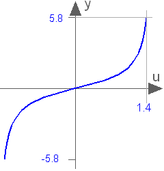
 Buildings.Controls.OBC.CDL.Continuous.Tan
Output the tangent of the input
Information
Block that outputs y = tan(u),
where
u is an input.
Connectors
| Type | Name | Description |
|---|---|---|
| input RealInput | u | Connector of Real input signal |
| output RealOutput | y | Connector of Real output signal |