Buildings.Electrical.AC.ThreePhasesBalanced.Sources.Examples

Package with example models

Information

This package contains examples for the use of models that can be found in Buildings.Electrical.AC.ThreePhasesBalanced.Sources.

Extends from Modelica.Icons.ExamplesPackage (Icon for packages containing runnable examples).

Package Content

Name Description
Buildings.Electrical.AC.ThreePhasesBalanced.Sources.Examples.FixedVoltageSource FixedVoltageSource This example illustrates how using a fixed voltage source
Buildings.Electrical.AC.ThreePhasesBalanced.Sources.Examples.PVPanels PVPanels This example illustrates how to use PV panel models
Buildings.Electrical.AC.ThreePhasesBalanced.Sources.Examples.VariablePowerSource VariablePowerSource This example illustrates how using a variable power source
Buildings.Electrical.AC.ThreePhasesBalanced.Sources.Examples.WindTurbine WindTurbine Example for the WindTurbine AC model

Buildings.Electrical.AC.ThreePhasesBalanced.Sources.Examples.FixedVoltageSource Buildings.Electrical.AC.ThreePhasesBalanced.Sources.Examples.FixedVoltageSource

This example illustrates how using a fixed voltage source

Buildings.Electrical.AC.ThreePhasesBalanced.Sources.Examples.FixedVoltageSource

Information

This example shows how to use a fixed voltage generator model.

Extends from Modelica.Icons.Example (Icon for runnable examples).

Modelica definition

model FixedVoltageSource "This example illustrates how using a fixed voltage source" extends Modelica.Icons.Example; Buildings.Electrical.AC.ThreePhasesBalanced.Loads.Inductive RL( P_nominal=-300, mode=Buildings.Electrical.Types.Load.FixedZ_steady_state, V_nominal=480) "Load model"; ThreePhasesBalanced.Sources.FixedVoltage grid( f=60, V=480, phiSou=0.34906585039887) "AC one phase electrical grid"; ThreePhasesBalanced.Sensors.Probe sen(V_nominal=480) "Probe that measures the voltage at the load"; equation connect(grid.terminal, RL.terminal); connect(grid.terminal, sen.term); end FixedVoltageSource;

Buildings.Electrical.AC.ThreePhasesBalanced.Sources.Examples.PVPanels Buildings.Electrical.AC.ThreePhasesBalanced.Sources.Examples.PVPanels

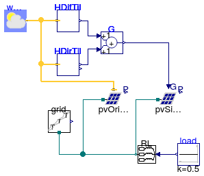
This example illustrates how to use PV panel models
Buildings.Electrical.AC.ThreePhasesBalanced.Sources.Examples.PVPanels

Information

This example shows how to use a simple PV model without orientation as well as a PV model with orientation. The power produced by the PV is partially consumed by the load, and the remaining part is fed into the grid.

Extends from Modelica.Icons.Example (Icon for runnable examples).

Modelica definition

model PVPanels "This example illustrates how to use PV panel models" extends Modelica.Icons.Example; Buildings.Electrical.AC.ThreePhasesBalanced.Loads.Inductive RL( mode=Types.Load.VariableZ_y_input, P_nominal=-2000, V_nominal=480) "Load taht consumes the power generted by the PVs"; Buildings.Electrical.AC.ThreePhasesBalanced.Sources.Grid grid(f=60, V=480) "Electrical grid model"; Modelica.Blocks.Sources.Constant load(k=0.5) "Load consumption"; BoundaryConditions.SolarIrradiation.DiffusePerez HDifTil( til=0.34906585039887, lat=0.65798912800186, azi=-0.78539816339745) "Diffuse irradiation on tilted surface"; BoundaryConditions.SolarIrradiation.DirectTiltedSurface HDirTil( til=0.34906585039887, lat=0.65798912800186, azi=-0.78539816339745) "Direct irradiation on tilted surface"; BoundaryConditions.WeatherData.ReaderTMY3 weaDat(computeWetBulbTemperature=false, filNam="modelica://Buildings/Resources/weatherdata/USA_CA_San.Francisco.Intl.AP.724940_TMY3.mos"); Modelica.Blocks.Math.Add G "Total irradiation on tilted surface"; ThreePhasesBalanced.Sources.PVSimple pvSimple(A=10, V_nominal=480) "PV array simplified"; ThreePhasesBalanced.Sources.PVSimpleOriented pvOriented( A=10, V_nominal=480, til=0.34906585039887, lat=0.65798912800186, azi=-0.78539816339745) "PV array oriented"; equation connect(grid.terminal, RL.terminal); connect(load.y, RL.y); connect(weaDat.weaBus, HDifTil.weaBus); connect(weaDat.weaBus, HDirTil.weaBus); connect(HDifTil.H, G.u1); connect(HDirTil.H, G.u2); connect(G.y, pvSimple.G); connect(pvSimple.terminal, RL.terminal); connect(weaDat.weaBus, pvOriented.weaBus); connect(pvOriented.terminal, RL.terminal); end PVPanels;

Buildings.Electrical.AC.ThreePhasesBalanced.Sources.Examples.VariablePowerSource Buildings.Electrical.AC.ThreePhasesBalanced.Sources.Examples.VariablePowerSource

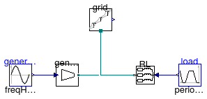
This example illustrates how using a variable power source
Buildings.Electrical.AC.ThreePhasesBalanced.Sources.Examples.VariablePowerSource

Information

This example shows how to use a variable generator model. The generator model has to be used together with a voltage source generator, which is in this example the grid model.

Extends from Modelica.Icons.Example (Icon for runnable examples).

Modelica definition

model VariablePowerSource "This example illustrates how using a variable power source" extends Modelica.Icons.Example; Buildings.Electrical.AC.ThreePhasesBalanced.Sources.Generator generator(f=60, phiGen=0.26179938779915) "AC generator model"; Modelica.Blocks.Sources.Sine generation( offset=200, startTime=1, amplitude=100, freqHz=0.05) "Generated power"; Buildings.Electrical.AC.ThreePhasesBalanced.Loads.Inductive RL( mode=Types.Load.VariableZ_y_input, P_nominal=-300, V_nominal=480) "Load model"; Buildings.Electrical.AC.ThreePhasesBalanced.Sources.Grid grid(f=60, V=480) "AC one phase electrical grid"; Modelica.Blocks.Sources.Trapezoid load( rising=2, width=3, falling=3, period=10, startTime=1, amplitude=0.8, offset=0.2) "Power consumption profile"; equation connect(generation.y, generator.P); connect(generator.terminal, RL.terminal); connect(grid.terminal, RL.terminal); connect(load.y, RL.y); end VariablePowerSource;

Buildings.Electrical.AC.ThreePhasesBalanced.Sources.Examples.WindTurbine Buildings.Electrical.AC.ThreePhasesBalanced.Sources.Examples.WindTurbine

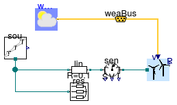
Example for the WindTurbine AC model
Buildings.Electrical.AC.ThreePhasesBalanced.Sources.Examples.WindTurbine

Information

This model illustrates the use of the wind turbine model, which is connected to a AC voltage source and a resistive load. This voltage source can represent the grid to which the circuit is connected. Wind data for San Francisco, CA, are used. The turbine cut-in wind speed is 3.5 m/s, and hence it is off in the first day when the wind speed is low.

Extends from Modelica.Icons.Example (Icon for runnable examples).

Connectors

TypeNameDescription
BusweaBusWeather bus

Modelica definition

model WindTurbine "Example for the WindTurbine AC model" extends Modelica.Icons.Example; Buildings.Electrical.AC.ThreePhasesBalanced.Sources.WindTurbine tur( table=[3.5, 0; 5.5, 100; 12, 900; 14, 1000; 25, 1000], h=10, scale=10, V_nominal=480) "Wind turbine"; Buildings.BoundaryConditions.WeatherData.ReaderTMY3 weaDat( computeWetBulbTemperature=false, filNam="modelica://Buildings/Resources/weatherdata/USA_CA_San.Francisco.Intl.AP.724940_TMY3.mos") "Weather data"; Buildings.BoundaryConditions.WeatherData.Bus weaBus "Weather bus"; Buildings.Electrical.AC.ThreePhasesBalanced.Loads.Resistive res(P_nominal=-500, V_nominal=480) "Resistive line"; Buildings.Electrical.AC.ThreePhasesBalanced.Sources.Grid sou(f=60, V=480) "Voltage source"; Buildings.Electrical.AC.ThreePhasesBalanced.Lines.TwoPortResistance lin(R=0.1) "Transmission line"; Buildings.Electrical.AC.ThreePhasesBalanced.Sensors.GeneralizedSensor sen "Generalized sensor"; equation connect(weaDat.weaBus, weaBus); connect(weaBus.winSpe, tur.vWin); connect(sou.terminal, lin.terminal_n); connect(sou.terminal, res.terminal); connect(lin.terminal_p, sen.terminal_n); connect(sen.terminal_p, tur.terminal); end WindTurbine;