Buildings.Electrical.AC.ThreePhasesBalanced.Lines.Examples

Package with example models

Information

This package contains examples for the use of models that can be found in Buildings.Electrical.AC.ThreePhasesBalanced.Lines.

Extends from Modelica.Icons.ExamplesPackage (Icon for packages containing runnable examples).

Package Content

Name Description
Buildings.Electrical.AC.ThreePhasesBalanced.Lines.Examples.ACLine ACLine Test model for single phase lines that use commercial cables
Buildings.Electrical.AC.ThreePhasesBalanced.Lines.Examples.ACLineMedium ACLineMedium Test model for a single phase line that uses medium voltage commercial cable information
Buildings.Electrical.AC.ThreePhasesBalanced.Lines.Examples.ACLine_L ACLine_L Test model for single phase inductive lines
Buildings.Electrical.AC.ThreePhasesBalanced.Lines.Examples.ACLine_R ACLine_R Test model for single phase resistive lines
Buildings.Electrical.AC.ThreePhasesBalanced.Lines.Examples.ACLine_RL ACLine_RL Test model for single phase inductive-resistive lines
Buildings.Electrical.AC.ThreePhasesBalanced.Lines.Examples.ACSimpleGrid ACSimpleGrid Test model for a network model
Buildings.Electrical.AC.ThreePhasesBalanced.Lines.Examples.ACSimpleGridMedium ACSimpleGridMedium Test model for a network model with medium voltage

Buildings.Electrical.AC.ThreePhasesBalanced.Lines.Examples.ACLine Buildings.Electrical.AC.ThreePhasesBalanced.Lines.Examples.ACLine

Test model for single phase lines that use commercial cables

Buildings.Electrical.AC.ThreePhasesBalanced.Lines.Examples.ACLine

Information

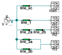
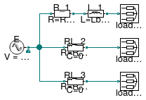
This example demonstrates how to use a line model to connect a source to a load that uses commercial cables.

The model has four different loads. The load sc_load represents a short circuit R=0. The current that flows through the load depends on the impedance of the line.

The remaining three loads R1, R2, and R3 are resistive loads. Each load is connected to the source with different configurations. However, the equivalent impedance between each load and the source is the same. Since the equivalent impedances are the same, each load draws the same current.

Extends from Modelica.Icons.Example (Icon for runnable examples).

Modelica definition

model ACLine "Test model for single phase lines that use commercial cables" extends Modelica.Icons.Example; ThreePhasesBalanced.Sources.FixedVoltage E( definiteReference=true, f=60, V=480) "Voltage source"; ThreePhasesBalanced.Loads.Impedance R1(R=10) "Resistive load 1"; ThreePhasesBalanced.Lines.Line line_1( P_nominal=5000, l=2000, mode=Types.CableMode.commercial, commercialCable=Transmission.LowVoltageCables.Cu50(), V_nominal=480) "Resistive line that connects to load 1"; ThreePhasesBalanced.Lines.Line line_2a( P_nominal=5000, mode=Types.CableMode.commercial, commercialCable=Transmission.LowVoltageCables.Cu50(), l=1000, V_nominal=480) "Resistive line that connects to load 2"; ThreePhasesBalanced.Loads.Impedance R2(R=10) "Resistive load 2"; ThreePhasesBalanced.Lines.Line line_2b( P_nominal=5000, mode=Types.CableMode.commercial, commercialCable=Transmission.LowVoltageCables.Cu50(), l=1000, V_nominal=480) "Resistive line that connects to load 2"; ThreePhasesBalanced.Lines.Line line_3a( P_nominal=5000, mode=Types.CableMode.commercial, commercialCable=Transmission.LowVoltageCables.Cu50(), l=4000, V_nominal=480) "Resistive line that connects to load 3"; ThreePhasesBalanced.Lines.Line line_3b( P_nominal=5000, mode=Types.CableMode.commercial, commercialCable=Transmission.LowVoltageCables.Cu50(), l=4000, V_nominal=480) "Resistive line that connects to load 3"; ThreePhasesBalanced.Loads.Impedance R3(R=10) "Resistive load 3"; ThreePhasesBalanced.Lines.Line line_sc( P_nominal=5000, l=2000, mode=Types.CableMode.commercial, commercialCable=Transmission.LowVoltageCables.Cu50(), V_nominal=480) "Line that connects the source and the short circuit"; ThreePhasesBalanced.Loads.Impedance load_sc(R=0) "Short circuit"; equation connect(line_1.terminal_p, R1.terminal); connect(E.terminal, line_1.terminal_n); connect(E.terminal, line_2a.terminal_n); connect(line_2a.terminal_p, line_2b.terminal_n); connect(line_2b.terminal_p, R2.terminal); connect(line_3a.terminal_p, R3.terminal); connect(line_3b.terminal_p, R3.terminal); connect(E.terminal, line_3a.terminal_n); connect(E.terminal, line_3b.terminal_n); connect(line_sc.terminal_p, load_sc.terminal); connect(E.terminal, line_sc.terminal_n); end ACLine;

Buildings.Electrical.AC.ThreePhasesBalanced.Lines.Examples.ACLineMedium Buildings.Electrical.AC.ThreePhasesBalanced.Lines.Examples.ACLineMedium

Test model for a single phase line that uses medium voltage commercial cable information

Buildings.Electrical.AC.ThreePhasesBalanced.Lines.Examples.ACLineMedium

Information

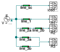
This example demonstrates how to use a line model to connect a source to a load that uses medium voltage commercial cable information.

The model has four different loads. The load sc_load represents a short circuit R=0. The current that flows through the load depends on the impedance of the line.

The remaining three loads R1, R2, and R3 are resistive loads. Each load is connected to the source with different configurations, however the equivalent impedance between each load and the source is the same. Since the equivalent impedances are the same, each load draws the same current.

Note:

ThreePhasesBalanced.Lines.Line line_1(

V_nominal=220,

P_nominal=5000,

l=2000,

redeclare Buildings.Electrical.Transmission.MediumVoltageCables.Generic

commercialCable = Buildings.Electrical.Transmission.MediumVoltageCables.Annealed_Al_10 ())

"Resistive line that connects to load 1"

The code snippet shows how a line model line_1 redeclared its record type in order to be Buildings.Electrical.Transmission.MediumVoltageCables.Generic.

Extends from Modelica.Icons.Example (Icon for runnable examples).

Modelica definition

model ACLineMedium "Test model for a single phase line that uses medium voltage commercial cable information " extends Modelica.Icons.Example; ThreePhasesBalanced.Sources.FixedVoltage E( definiteReference=true, V=15000, f=60) "Voltage source"; ThreePhasesBalanced.Loads.Impedance R1(R=10) "Resistive load 1"; ThreePhasesBalanced.Lines.Line line_1( P_nominal=5000, l=2000, redeclare Buildings.Electrical.Transmission.MediumVoltageCables.Generic commercialCable= Buildings.Electrical.Transmission.MediumVoltageCables.Annealed_Al_10(), V_nominal=15000) "Resistive line that connects to load 1"; ThreePhasesBalanced.Lines.Line line_2a( P_nominal=5000, l=1000, redeclare Buildings.Electrical.Transmission.MediumVoltageCables.Generic commercialCable= Buildings.Electrical.Transmission.MediumVoltageCables.Annealed_Al_10(), V_nominal=15000) "Resistive line that connects to load 2"; ThreePhasesBalanced.Loads.Impedance R2(R=10) "Resistive load 2"; ThreePhasesBalanced.Lines.Line line_2b( P_nominal=5000, l=1000, redeclare Buildings.Electrical.Transmission.MediumVoltageCables.Generic commercialCable= Buildings.Electrical.Transmission.MediumVoltageCables.Annealed_Al_10(), V_nominal=15000) "Resistive line that connects to load 2"; ThreePhasesBalanced.Lines.Line line_3a( P_nominal=5000, l=4000, redeclare Buildings.Electrical.Transmission.MediumVoltageCables.Generic commercialCable= Buildings.Electrical.Transmission.MediumVoltageCables.Annealed_Al_10(), V_nominal=15000) "Resistive line that connects to load 3"; ThreePhasesBalanced.Lines.Line line_3b( P_nominal=5000, l=4000, redeclare Buildings.Electrical.Transmission.MediumVoltageCables.Generic commercialCable= Buildings.Electrical.Transmission.MediumVoltageCables.Annealed_Al_10(), V_nominal=15000) "Resistive line that connects to load 3"; ThreePhasesBalanced.Loads.Impedance R3(R=10) "Resistive load 3"; ThreePhasesBalanced.Lines.Line line_sc( P_nominal=5000, l=2000, redeclare Buildings.Electrical.Transmission.MediumVoltageCables.Generic commercialCable= Buildings.Electrical.Transmission.MediumVoltageCables.Annealed_Al_10(), V_nominal=15000) "Line that connects the source and the short circuit"; ThreePhasesBalanced.Loads.Impedance load_sc(R=0) "Short circuit"; equation connect(line_1.terminal_p, R1.terminal); connect(E.terminal, line_1.terminal_n); connect(E.terminal, line_2a.terminal_n); connect(line_2a.terminal_p, line_2b.terminal_n); connect(line_2b.terminal_p, R2.terminal); connect(line_3a.terminal_p, R3.terminal); connect(line_3b.terminal_p, R3.terminal); connect(E.terminal, line_3a.terminal_n); connect(E.terminal, line_3b.terminal_n); connect(line_sc.terminal_p, load_sc.terminal); connect(E.terminal, line_sc.terminal_n); end ACLineMedium;

Buildings.Electrical.AC.ThreePhasesBalanced.Lines.Examples.ACLine_L Buildings.Electrical.AC.ThreePhasesBalanced.Lines.Examples.ACLine_L

Test model for single phase inductive lines

Buildings.Electrical.AC.ThreePhasesBalanced.Lines.Examples.ACLine_L

Information

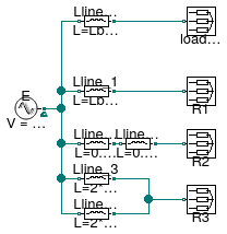
This example demonstrates how to use a purely inductive line model to connect a source to a load.

The model has four different loads. The load sc_load represents a short circuit R=0. The current that flows through the load depends on the inductance of the line.

The remaining three loads R1, R2, and R3 are resistive loads. Each load is connected to the source with different configurations. However, the equivalent impedance between each load and the source is the same. Since the equivalent impedances are the same, each load draws the same current.

Extends from Modelica.Icons.Example (Icon for runnable examples).

Parameters

TypeNameDefaultDescription
InductanceLbase10/2/Modelica.Constants.pi/60Base value for the line inductances [H]

Modelica definition

model ACLine_L "Test model for single phase inductive lines" extends Modelica.Icons.Example; parameter Modelica.SIunits.Inductance Lbase=10/2/Modelica.Constants.pi/60 "Base value for the line inductances"; ThreePhasesBalanced.Sources.FixedVoltage E( definiteReference=true, f=60, V=480) "Voltage source"; ThreePhasesBalanced.Loads.Impedance R1(R=10) "Resistive load 1"; ThreePhasesBalanced.Loads.Impedance R2(R=10) "Resistive load 2"; ThreePhasesBalanced.Loads.Impedance R3(R=10) "Resistive load 3"; ThreePhasesBalanced.Loads.Impedance load_sc(R=0) "Short circuit"; ThreePhasesBalanced.Lines.TwoPortInductance Lline_sc(L=Lbase) "Inductive line connected to the short circuit"; ThreePhasesBalanced.Lines.TwoPortInductance Lline_1(L=Lbase) "Inductive line connected to load 1"; ThreePhasesBalanced.Lines.TwoPortInductance Lline_2a(L=0.5*Lbase) "Inductive line connected to load 2"; ThreePhasesBalanced.Lines.TwoPortInductance Lline_2b(L=0.5*Lbase) "Inductive line connected to load 2"; ThreePhasesBalanced.Lines.TwoPortInductance Lline_3(L=2*Lbase) "Inductive line connected to load 3"; ThreePhasesBalanced.Lines.TwoPortInductance Lline_3b(L=2*Lbase) "Inductive line connected to load 3"; equation connect(E.terminal, Lline_sc.terminal_n); connect(Lline_sc.terminal_p, load_sc.terminal); connect(E.terminal, Lline_1.terminal_n); connect(Lline_1.terminal_p, R1.terminal); connect(E.terminal, Lline_2a.terminal_n); connect(Lline_2a.terminal_p, Lline_2b.terminal_n); connect(Lline_2b.terminal_p, R2.terminal); connect(E.terminal, Lline_3.terminal_n); connect(E.terminal, Lline_3b.terminal_n); connect(Lline_3.terminal_p, R3.terminal); connect(Lline_3b.terminal_p, R3.terminal); end ACLine_L;

Buildings.Electrical.AC.ThreePhasesBalanced.Lines.Examples.ACLine_R Buildings.Electrical.AC.ThreePhasesBalanced.Lines.Examples.ACLine_R

Test model for single phase resistive lines

Buildings.Electrical.AC.ThreePhasesBalanced.Lines.Examples.ACLine_R

Information

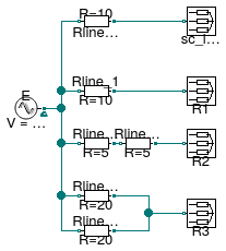
This example demonstrates how to use a resistive line model to connect a source to a load.

The model has four different loads. The load sc_load represents a short circuit R=0. The current that flows through the load depends on the resistance of the line.

The remaining three loads R1, R2, and R3 are resistive loads. Each load is connected to the source with different configurations. However, the equivalent resistance between each load and the source is the same. Since the equivalent resistances are the same, each load draws the same current.

Extends from Modelica.Icons.Example (Icon for runnable examples).

Modelica definition

model ACLine_R "Test model for single phase resistive lines" extends Modelica.Icons.Example; ThreePhasesBalanced.Sources.FixedVoltage E( definiteReference=true, f=60, V=480) "Voltage source"; ThreePhasesBalanced.Loads.Impedance R1(R=10) "Resistive load 1"; ThreePhasesBalanced.Loads.Impedance R2(R=10) "Resistive load 2"; ThreePhasesBalanced.Loads.Impedance R3(R=10) "Resistive load 3"; ThreePhasesBalanced.Loads.Impedance sc_load(R=0) "Short circuit load"; ThreePhasesBalanced.Lines.TwoPortResistance Rline_sc(R=10, useHeatPort=false) "Resistive line that connects to the short circuit"; ThreePhasesBalanced.Lines.TwoPortResistance Rline_1(R=10) "Resistive line that connects to load 1"; ThreePhasesBalanced.Lines.TwoPortResistance Rline_2a(R=5) "Resistive line that connects to load 2"; ThreePhasesBalanced.Lines.TwoPortResistance Rline_2b(R=5) "Resistive line that connects to load 2"; ThreePhasesBalanced.Lines.TwoPortResistance Rline_3a(R=20) "Resistive line that connects to load 3"; ThreePhasesBalanced.Lines.TwoPortResistance Rline_3b(R=20) "Resistive line that connects to load 3"; equation connect(E.terminal, Rline_sc.terminal_n); connect(Rline_sc.terminal_p, sc_load.terminal); connect(E.terminal, Rline_1.terminal_n); connect(Rline_1.terminal_p, R1.terminal); connect(E.terminal, Rline_2a.terminal_n); connect(Rline_2a.terminal_p, Rline_2b.terminal_n); connect(Rline_2b.terminal_p, R2.terminal); connect(E.terminal, Rline_3a.terminal_n); connect(E.terminal, Rline_3b.terminal_n); connect(Rline_3a.terminal_p, R3.terminal); connect(Rline_3b.terminal_p, R3.terminal); end ACLine_R;

Buildings.Electrical.AC.ThreePhasesBalanced.Lines.Examples.ACLine_RL Buildings.Electrical.AC.ThreePhasesBalanced.Lines.Examples.ACLine_RL

Test model for single phase inductive-resistive lines

Buildings.Electrical.AC.ThreePhasesBalanced.Lines.Examples.ACLine_RL

Information

This example demonstrates how to use a resistive-inductive line model to connect a source to a load.

The model has three loads load_sc_1, load_sc_2, and load_sc_3 representing short circuits R=0. The current that flows through the load depends on the impedance of the line.

Each load is connected to the source with different configurations. However, the equivalent impedance between each load and the source is the same. Since the equivalent impedances are the same, each load draws the same current.

Note: The line model RL_3 is the same as RL_2 but it uses dynamic phasors.

Extends from Modelica.Icons.Example (Icon for runnable examples).

Parameters

TypeNameDefaultDescription
ResistanceRbase10Base value for the line resistance [Ohm]
InductanceLbaseRbase/2/Modelica.Constants.p...Base value for the line inductance [H]

Modelica definition

model ACLine_RL "Test model for single phase inductive-resistive lines" extends Modelica.Icons.Example; parameter Modelica.SIunits.Resistance Rbase=10 "Base value for the line resistance"; parameter Modelica.SIunits.Inductance Lbase=Rbase/2/Modelica.Constants.pi/60 "Base value for the line inductance"; ThreePhasesBalanced.Sources.FixedVoltage E( definiteReference=true, f=60, V=480) "Voltage source"; ThreePhasesBalanced.Loads.Impedance load_sc_1(R=0) "Short circuit 1"; ThreePhasesBalanced.Loads.Impedance load_sc_2(R=0) "Short circuit 2"; ThreePhasesBalanced.Lines.TwoPortRL RL_2(R=Rbase, L=Lbase) "Resistive-Inductive line connected to short circuit 2"; ThreePhasesBalanced.Lines.TwoPortResistance R_1(R=Rbase) "Resistance line connected to short circuit 1"; ThreePhasesBalanced.Lines.TwoPortInductance L_1(L=Lbase) "Inductance line connected to short circuit 1"; ThreePhasesBalanced.Lines.TwoPortRL RL_3( R=Rbase, L=Lbase, mode=Buildings.Electrical.Types.Load.FixedZ_dynamic) "Dynamic resistive-inductive line connected to short circuit 3"; ThreePhasesBalanced.Loads.Impedance load_sc_3(R=0) "Short circuit 3"; equation connect(E.terminal, R_1.terminal_n); connect(R_1.terminal_p, L_1.terminal_n); connect(L_1.terminal_p, load_sc_1.terminal); connect(E.terminal, RL_2.terminal_n); connect(RL_2.terminal_p, load_sc_2.terminal); connect(E.terminal, RL_3.terminal_n); connect(RL_3.terminal_p, load_sc_3.terminal); end ACLine_RL;

Buildings.Electrical.AC.ThreePhasesBalanced.Lines.Examples.ACSimpleGrid Buildings.Electrical.AC.ThreePhasesBalanced.Lines.Examples.ACSimpleGrid

Test model for a network model

Buildings.Electrical.AC.ThreePhasesBalanced.Lines.Examples.ACSimpleGrid

Information

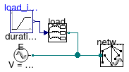
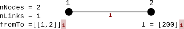
This example demonstrates how to use a network model to connect a source to a load. In this simple case the network has two nodes that are connected by a commercial line cable.

At the beginning of the simulation the load consumes power while at the and it produces power. The voltage at the load at the beginning is lower than the nominal RMS voltage (480 V) while at the end of the simulation it is higher. The voltage drop and increase are due to the presence of the cable between the source and the load.

The network uses cables of the type LowVoltageCable.Cu35 with a length of 200 m.

The picture below describes the grid topology.

image

Extends from Modelica.Icons.Example (Icon for runnable examples).

Modelica definition

model ACSimpleGrid "Test model for a network model" extends Modelica.Icons.Example; ThreePhasesBalanced.Lines.Network network(redeclare Buildings.Electrical.Transmission.Grids.TestGrid2Nodes grid, V_nominal=480) "Network model that represents the connection between the source and the load"; ThreePhasesBalanced.Loads.Inductive load( P_nominal=2500, mode=Types.Load.VariableZ_P_input, V_nominal=480) "Load connected to the network"; ThreePhasesBalanced.Sources.FixedVoltage E(f=60, V=480) "Voltage source"; Modelica.Blocks.Sources.Ramp load_inputs( height=5000, duration=2, offset=-2000, startTime=0.5) "Input signal for the power consumption of the loads"; equation connect(load.terminal, network.terminal[2]); connect(E.terminal, network.terminal[1]); connect(load_inputs.y, load.Pow); end ACSimpleGrid;

Buildings.Electrical.AC.ThreePhasesBalanced.Lines.Examples.ACSimpleGridMedium Buildings.Electrical.AC.ThreePhasesBalanced.Lines.Examples.ACSimpleGridMedium

Test model for a network model with medium voltage

Buildings.Electrical.AC.ThreePhasesBalanced.Lines.Examples.ACSimpleGridMedium

Information

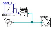
This example demonstrates how to use a network model to connect a source to a load (using a medium voltage cable). In this simple case the network has two nodes that are connected by a commercial line cable.

At the beginning of the simulation the load consumes power while at the end it produces power. The voltage at the load at the beginning is lower than the nominal RMS voltage (15 kV) while at the end of the simulation it is higher. The voltage drop and increase are due to the presence of the cable between the source and the load.

The network uses cables of the type MediumVoltageCables.Annealed_Al_30 with a length of 200 m.

The picture below describes the grid topology.

image

Note:

The cables are usually defined using the LowVoltageCable.Generic type. In order to use a medium voltage cable it is necessary to redeclare the type of the record commercialCable.

ThreePhasesBalanced.Lines.Network network(

redeclare Buildings.Electrical.Transmission.Grids.TestGrid2NodesMedium grid,

lines( redeclare Buildings.Electrical.Transmission.MediumVoltageCables.Generic

commercialCable = network.grid.cables,

each V_nominal = network.V_nominal),

V_nominal=15000)

The code snippet shows how each line that is part of the vector lines is redeclared in order to have as type the record Buildings.Electrical.Transmission.MediumVoltageCables.Generic. The lines are initialized using the cables of the grid network.grid.cables. All the lines have the same nominal voltage each V_nominal = network.V_nominal.

Extends from Modelica.Icons.Example (Icon for runnable examples).

Modelica definition

model ACSimpleGridMedium "Test model for a network model with medium voltage" extends Modelica.Icons.Example; ThreePhasesBalanced.Lines.Network network( redeclare Buildings.Electrical.Transmission.Grids.TestGrid2NodesMedium grid, lines(redeclare Buildings.Electrical.Transmission.MediumVoltageCables.Generic commercialCable=network.grid.cables, each V_nominal=network.V_nominal), V_nominal=15000) "Network model that represents the connection between the source and the load"; ThreePhasesBalanced.Loads.Inductive load( mode=Types.Load.VariableZ_P_input, P_nominal=250000, V_nominal=15000) "Load connected to the network"; ThreePhasesBalanced.Sources.FixedVoltage E(V=15000, f=60) "Voltage source"; Modelica.Blocks.Sources.Ramp load_inputs( height=5000, duration=2, offset=-2000, startTime=0.5) "Input signal for the power consumption of the loads"; equation connect(load.terminal, network.terminal[2]); connect(E.terminal, network.terminal[1]); connect(load_inputs.y, load.Pow); end ACSimpleGridMedium;