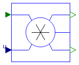
Buildings.HeatTransfer.Radiosity
Package with models for radiosity transfer
Information
This package provides component models for the infrared radiative heat exchange of window assemblies. The models are according to TARCOG 2006, except for the outdoor radiosity, which is computed by Buildings.HeatTransfer.Radiosity.OutdoorRadiosity. The outdoor radiosity is different from the TARCOG implementation so that the same equations are used for windows as are used for opaque walls in the room heat transfer model of the package Buildings.ThermalZones.Detailed.
By definition, incoming and outcoming radiosity are both positive. This is required to connect incoming and outcoming radiosity connectors.
References
TARCOG 2006: Carli, Inc., TARCOG: Mathematical models for calculation of thermal performance of glazing systems with our without shading devices, Technical Report, Oct. 17, 2006.
Extends from Modelica.Icons.VariantsPackage (Icon for package containing variants).
Package Content
| Name | Description |
|---|---|
| Generate constant radiosity signal | |
| Model for indoor radiosity | |
| Model for an opaque surface | |
| Model for the outdoor radiosity that strikes the window | |
| Splits the incoming radiosity into two flows based on an input signal | |
| Collection of models that illustrate model use and test models | |
| Package with base classes for Buildings.HeatTransfer.Radiosity |
 Buildings.HeatTransfer.Radiosity.Constant
Generate constant radiosity signal

Information
Constant radiosity source. This model requires k ≥ 0.
This model is used in Buildings.HeatTransfer.BaseClasses.DummyConstructionExterior.
Extends from Modelica.Blocks.Icons.Block (Basic graphical layout of input/output block).
Parameters
| Type | Name | Default | Description |
|---|---|---|---|
| Real | k | Radiosity that leaves this component (k ≥ 0) |
Connectors
| Type | Name | Description |
|---|---|---|
| output RadiosityOutflow | JOut | [W] |
Modelica definition
 Buildings.HeatTransfer.Radiosity.IndoorRadiosity
Model for indoor radiosity

Information
Model for the indoor emissive power that hits a window. The computation is according to TARCOG 2006.
References
TARCOG 2006: Carli, Inc., TARCOG: Mathematical models for calculation of thermal performance of glazing systems with our without shading devices, Technical Report, Oct. 17, 2006.
Extends from Buildings.HeatTransfer.Radiosity.BaseClasses.RadiosityOneSurface (Model for the radiosity balance of a device with one surface), Buildings.HeatTransfer.Radiosity.BaseClasses.ParametersOneSurface (Parameters that are used to model one surface).
Parameters
| Type | Name | Default | Description |
|---|---|---|---|
| Area | A | Surface area [m2] | |
| Emissivity | absIR | 1 | Infrared absorptivity [1] |
| ReflectionCoefficient | rhoIR | 0 | Infrared reflectivity [1] |
| TransmissionCoefficient | tauIR | 0 | Infrared transmissivity [1] |
| Boolean | linearize | false | Set to true to linearize emissive power |
| Temperature | T0 | 293.15 | Temperature used to linearize radiative heat transfer [K] |
Connectors
| Type | Name | Description |
|---|---|---|
| input RadiosityInflow | JIn | Incoming radiosity [W] |
| output RadiosityOutflow | JOut | Outgoing radiosity [W] |
| HeatPort_a | heatPort | Heat port of the surface |
Modelica definition
 Buildings.HeatTransfer.Radiosity.OpaqueSurface
Model for an opaque surface

Information
Model for the emissive power of an opaque surface.Extends from Buildings.HeatTransfer.Radiosity.BaseClasses.RadiosityOneSurface (Model for the radiosity balance of a device with one surface), Buildings.HeatTransfer.Radiosity.BaseClasses.ParametersOneSurface (Parameters that are used to model one surface).
Parameters
| Type | Name | Default | Description |
|---|---|---|---|
| Area | A | Surface area [m2] | |
| Emissivity | absIR | Infrared absorptivity [1] | |
| ReflectionCoefficient | rhoIR | 1 - absIR | Infrared reflectivity [1] |
| TransmissionCoefficient | tauIR | 1 - rhoIR - absIR | Infrared transmissivity [1] |
| Boolean | linearize | false | Set to true to linearize emissive power |
| Temperature | T0 | 293.15 | Temperature used to linearize radiative heat transfer [K] |
Connectors
| Type | Name | Description |
|---|---|---|
| input RadiosityInflow | JIn | Incoming radiosity [W] |
| output RadiosityOutflow | JOut | Outgoing radiosity [W] |
| HeatPort_a | heatPort | Heat port of this surface |
Modelica definition
 Buildings.HeatTransfer.Radiosity.OutdoorRadiosity
Model for the outdoor radiosity that strikes the window

Information
Model for the infrared radiosity balance of the outdoor environment.
Parameters
| Type | Name | Default | Description |
|---|---|---|---|
| Area | A | Area of receiving surface [m2] | |
| Real | vieFacSky | View factor from receiving surface to sky (=1 for roofs) | |
| Boolean | linearize | false | Set to true to linearize emissive power |
| Temperature | T0 | 293.15 | Temperature used to linearize radiative heat transfer [K] |
Connectors
| Type | Name | Description |
|---|---|---|
| input RealInput | TOut | Outside temperature [K] |
| input RealInput | TBlaSky | Black body sky temperature [K] |
| output RadiosityOutflow | JOut | Radiosity that flows out of component [W] |
Modelica definition
 Buildings.HeatTransfer.Radiosity.RadiositySplitter
Splits the incoming radiosity into two flows based on an input signal

Information
This blocks splits the incoming radiosity into two fluxes according to
JOut,1 = u JIn,
JOut,2 = (1-u) JIn.
This block may be used to split the radiosity flux into a fraction that strikes the shaded part of a window, and a fraction that strikes the non-shaded part.
Extends from Modelica.Blocks.Icons.Block (Basic graphical layout of input/output block).
Connectors
| Type | Name | Description |
|---|---|---|
| input RadiosityInflow | JIn | Inflowing radiosity [W] |
| input RealInput | u | u times incoming radiosity |
| output RadiosityOutflow | JOut_1 | u times incoming radiosity [W] |
| output RadiosityOutflow | JOut_2 | (1-u) times incoming radiosity [W] |
