Collection of models that illustrate model use and test models
Information
This package contains examples for the use of models that can be found in
Buildings.HeatTransfer.
Extends from Modelica.Icons.ExamplesPackage (Icon for packages containing runnable examples).
Package Content
| Name |
Description |
 ConductorInitialization ConductorInitialization
|
Test model for heat conductor initialization |
 ConductorMultiLayer ConductorMultiLayer
|
Test model for heat conductor |
 ConductorMultiLayer2 ConductorMultiLayer2
|
Test model for multi layer heat conductor with one
state added at the surface a of the construction |
 ConductorMultiLayer3 ConductorMultiLayer3
|
Test model for multi layer heat conductor with one
state added at the surfaces a and b of the construction |
 ConductorSingleLayer ConductorSingleLayer
|
Test model for heat conductor |
 ConductorSingleLayer2 ConductorSingleLayer2
|
Test model for single layer heat conductor without
states added at the surfaces of the construction |
 ConductorSingleLayerCylinder ConductorSingleLayerCylinder
|
Test model for heat conduction in a cylinder |
 ConductorSingleLayerPCM ConductorSingleLayerPCM
|
Test model for heat conductor |
 ConductorSteadyStateTransient ConductorSteadyStateTransient
|
Test model for heat conductor |
 ConductorStepResponse ConductorStepResponse
|
Test model for heat conductor |
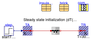
Test model for heat conductor initialization
Information
This example illustrates how to initialize heat conductors in steady state and with
predefined temperatures.
Extends from Modelica.Icons.Example (Icon for runnable examples).
Parameters
| Type | Name | Default | Description |
|---|
| Brick | brick | | |
| InsulationBoard | insulation | | |
| Generic | compositeWall | | Composite wall consisting of insulation and material |
Modelica definition
model ConductorInitialization
extends Modelica.Icons.Example;
Buildings.HeatTransfer.Sources.FixedTemperature TB(T=303.15);
Buildings.HeatTransfer.Sources.PrescribedTemperature TA;
parameter Buildings.HeatTransfer.Data.Solids.Brick brick(x=0.18, nStaRef=3,
nSta=5);
parameter Buildings.HeatTransfer.Data.Solids.InsulationBoard insulation(x=0.05, nStaRef=2,
nSta=5);
parameter Buildings.HeatTransfer.Data.OpaqueConstructions.Generic compositeWall(
material={insulation,brick}, nLay=2)
;
Buildings.HeatTransfer.Conduction.MultiLayer conS1(
A=2,
steadyStateInitial=true,
layers=compositeWall,
stateAtSurface_a=false,
stateAtSurface_b=false);
Modelica.Blocks.Sources.Step step(
height=10,
offset=283.15,
startTime=43200);
equation
connect(step.y, TA.T);
connect(conS1.port_b, TB.port);
connect(TA.port, conS1.port_a);
end ConductorInitialization;
Test model for heat conductor

Information
This example illustrates how to use a solid material, set its heat capacity to zero,
and then use this material in a multi-layer construction.
The plot window shows that the insulation is computed in steady state, where
as the brick is computed using transient heat conduction.
Extends from Modelica.Icons.Example (Icon for runnable examples).
Modelica definition
model ConductorMultiLayer
extends Modelica.Icons.Example;
Buildings.HeatTransfer.Sources.FixedTemperature TB(T=293.15);
Buildings.HeatTransfer.Sources.PrescribedTemperature TA;
Modelica.Blocks.Sources.Step step(
height=10,
offset=293.15,
startTime=43200);
Buildings.HeatTransfer.Conduction.MultiLayer con(
steadyStateInitial=false,
redeclare Buildings.HeatTransfer.Data.OpaqueConstructions.Insulation100Concrete200
layers,
A=0.1,
stateAtSurface_b=false);
Buildings.HeatTransfer.Convection.Interior conv(
A=0.1,
til=Buildings.Types.Tilt.Wall)
;
equation
connect(step.y, TA.T);
connect(con.port_b, TB.port);
connect(conv.fluid, TA.port);
connect(conv.solid, con.port_a);
end ConductorMultiLayer;
Test model for multi layer heat conductor with one
state added at the surface a of the construction

Information
This example is similar to
Buildings.HeatTransfer.Examples.ConductorMultiLayer. The main difference
is that a state is added at the surface a of the construction.
Extends from ConductorMultiLayer (Test model for heat conductor).
Modelica definition
Test model for multi layer heat conductor with one
state added at the surfaces a and b of the construction

Information
This example is similar to
Buildings.HeatTransfer.Examples.ConductorMultiLayer. The main difference
is that a state is added at the surfaces a and b of the construction.
Extends from ConductorMultiLayer (Test model for heat conductor).
Modelica definition
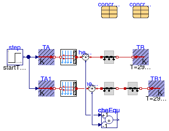
Test model for heat conductor
Information
This example tests if two conductors in series computes the same heat transfer
as one conductor with twice the thickness.
Extends from Modelica.Icons.Example (Icon for runnable examples).
Parameters
Modelica definition
model ConductorSingleLayer
extends Modelica.Icons.Example;
Buildings.HeatTransfer.Conduction.SingleLayer con(A=1, material=concrete200,
stateAtSurface_b=true);
Buildings.HeatTransfer.Sources.FixedTemperature TB(T=293.15);
Buildings.HeatTransfer.Sources.PrescribedTemperature TA;
Modelica.Blocks.Sources.Step step(
height=10,
offset=293.15,
startTime=3600);
Buildings.HeatTransfer.Conduction.SingleLayer con1(
A=1, material=concrete100,
stateAtSurface_b=false);
Buildings.HeatTransfer.Sources.FixedTemperature TB1( T=293.15);
Buildings.HeatTransfer.Sources.PrescribedTemperature TA1;
Buildings.HeatTransfer.Conduction.SingleLayer con2(
A=1, material=concrete100,
stateAtSurface_a=false,
stateAtSurface_b=true);
Modelica.Thermal.HeatTransfer.Sensors.HeatFlowSensor heaFlo2;
Modelica.Thermal.HeatTransfer.Sensors.HeatFlowSensor heaFlo1;
parameter Buildings.HeatTransfer.Data.Solids.Concrete concrete200(x=0.2, nSta=4);
parameter Buildings.HeatTransfer.Data.Solids.Concrete concrete100(x=0.1, nSta=2);
Buildings.HeatTransfer.Convection.Interior conv1( A=1, til=Buildings.Types.Tilt.Wall)
;
Buildings.HeatTransfer.Convection.Interior conv2( A=1, til=Buildings.Types.Tilt.Wall)
;
Modelica.Blocks.Math.Add cheEqu(k2=-1) ;
equation
connect(con.port_b, TB.port);
connect(step.y, TA.T);
connect(step.y, TA1.T);
connect(con1.port_b, con2.port_a);
connect(con2.port_b, TB1.port);
connect(heaFlo2.port_b, con1.port_a);
connect(heaFlo1.port_b, con.port_a);
connect(TA.port, conv1.fluid);
connect(TA1.port, conv2.fluid);
connect(conv2.solid, heaFlo2.port_a);
connect(conv1.solid, heaFlo1.port_a);
connect(heaFlo1.Q_flow, cheEqu.u1);
connect(heaFlo2.Q_flow, cheEqu.u2);
end ConductorSingleLayer;
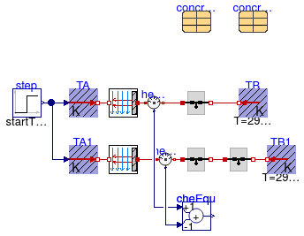
Test model for single layer heat conductor without
states added at the surfaces of the construction
Information
This example is similar to
Buildings.HeatTransfer.Examples.ConductorSingleLayer. The main difference
is that there are no states at the surfaces of the construction.
Extends from ConductorSingleLayer (Test model for heat conductor).
Parameters
Modelica definition
model ConductorSingleLayer2
extends ConductorSingleLayer(
con(stateAtSurface_a=false, stateAtSurface_b=false),
con1(stateAtSurface_a=false, stateAtSurface_b=false),
con2(stateAtSurface_a=false, stateAtSurface_b=false));
end ConductorSingleLayer2;
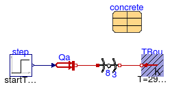
Test model for heat conduction in a cylinder
Information
This example tests a circular conductor with a constant temperature at his boundary.
Extends from Modelica.Icons.Example (Icon for runnable examples).
Parameters
Modelica definition
model ConductorSingleLayerCylinder
extends Modelica.Icons.Example;
parameter Modelica.SIunits.HeatFlowRate Q_flow=50;
Buildings.HeatTransfer.Conduction.SingleLayerCylinder
con( material=concrete,
steadyStateInitial=false,
final nSta=8,
r_a=0.1,
r_b=3,
h=10,
TInt_start=293.15,
TExt_start=293.15);
Buildings.HeatTransfer.Sources.PrescribedHeatFlow Qa;
parameter Buildings.HeatTransfer.Data.Soil.Concrete concrete;
Modelica.Blocks.Sources.Step step(
offset=0,
height=Q_flow,
startTime=3600);
Buildings.HeatTransfer.Sources.FixedTemperature TBou(T=293.15)
;
equation
connect(Qa.port, con.port_a);
connect(step.y, Qa.Q_flow);
connect(TBou.port, con.port_b);
end ConductorSingleLayerCylinder;
Test model for heat conductor
Information
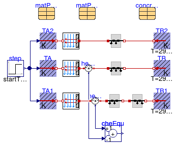
This example tests the implementation of the phase-change material (PCM) model.
The phase-change material matPCM is exposed to the same boundary
conditions as the non phase-change material.
In the construction conPCM2, the phase change is around 20.5 °C.
In the construction conPCM, the phase change is around 40.5 °C, which
is above the temperature range simulated in this model.
Therefore, the same result is expected for the PCM material conPCM
as is for two conductors in series.
Note that in case of using matPCM, the internal energy is
the dependent variable, whereas in case of two conductors in series, the temperature
is the dependent variable. However, both models will
produce the same results.
The cheEqu block computes the difference between the heat fluxes,
which should be equal except for the numerical approximation error of the solver.
Extends from Modelica.Icons.Example (Icon for runnable examples).
Parameters
| Type | Name | Default | Description |
|---|
| Concrete | concrete100 | | Non-PCM material |
| Generic | matPCM | | PCM material with phase change near 40 degC |
| Generic | matPCM2 | | PCM material with phase change near room temperature |
Modelica definition
model ConductorSingleLayerPCM
extends Modelica.Icons.Example;
Buildings.HeatTransfer.Sources.FixedTemperature TB(T=293.15)
;
Buildings.HeatTransfer.Sources.PrescribedTemperature TA
;
Modelica.Blocks.Sources.Step step(
height=10,
offset=293.15,
startTime=360);
Buildings.HeatTransfer.Sources.FixedTemperature TB1(T=293.15)
;
Buildings.HeatTransfer.Sources.PrescribedTemperature TA1
;
Modelica.Thermal.HeatTransfer.Sensors.HeatFlowSensor heaFlo2
;
Modelica.Thermal.HeatTransfer.Sensors.HeatFlowSensor heaFlo1
;
Modelica.Blocks.Math.Add cheEqu(k2=-1) ;
parameter Buildings.HeatTransfer.Data.Solids.Concrete concrete100(x=0.1, nStaRef=4)
;
Buildings.HeatTransfer.Convection.Interior conv1( A=1, til=Buildings.Types.Tilt.Wall)
;
Buildings.HeatTransfer.Convection.Interior conv2( A=1, til=Buildings.Types.Tilt.Wall)
;
Buildings.HeatTransfer.Conduction.SingleLayer conPCM(
A=1,
material=matPCM,
stateAtSurface_b=true)
;
Buildings.HeatTransfer.Conduction.SingleLayer con1(
A=1, material=concrete100,
stateAtSurface_b=false) ;
Buildings.HeatTransfer.Conduction.SingleLayer con2(
A=1, material=concrete100,
stateAtSurface_a=false,
stateAtSurface_b=true) ;
parameter Buildings.HeatTransfer.Data.SolidsPCM.Generic matPCM(
x=0.2,
k=1.4,
c=840,
d=2240,
nSta=4,
TSol=273.15 + 40.49,
TLiq=273.15 + 40.51,
LHea=100000) ;
Buildings.HeatTransfer.Sources.PrescribedTemperature TA2
;
Buildings.HeatTransfer.Convection.Interior conv3( A=1, til=Buildings.Types.Tilt.Wall)
;
Buildings.HeatTransfer.Conduction.SingleLayer conPCM2(
A=1,
material=matPCM2,
stateAtSurface_b=false)
;
Buildings.HeatTransfer.Sources.FixedTemperature TB2(T=293.15)
;
parameter Buildings.HeatTransfer.Data.SolidsPCM.Generic matPCM2(
x=0.2,
k=1.4,
c=840,
d=2240,
nSta=4,
TSol=273.15 + 20.49,
TLiq=273.15 + 20.51,
LHea=100000) ;
equation
connect(step.y, TA.T);
connect(step.y, TA1.T);
connect(cheEqu.u1, heaFlo2.Q_flow);
connect(cheEqu.u2, heaFlo1.Q_flow);
connect(TA.port, conv1.fluid);
connect(TA1.port, conv2.fluid);
connect(conv2.solid, heaFlo2.port_a);
connect(conv1.solid, heaFlo1.port_a);
connect(heaFlo1.port_b, conPCM.port_a);
connect(conPCM.port_b, TB.port);
connect(heaFlo2.port_b, con1.port_a);
connect(con1.port_b, con2.port_a);
connect(con2.port_b, TB1.port);
connect(step.y, TA2.T);
connect(TA2.port, conv3.fluid);
connect(conv3.solid, conPCM2.port_a);
connect(conPCM2.port_b, TB2.port);
end ConductorSingleLayerPCM;
Test model for heat conductor
Information
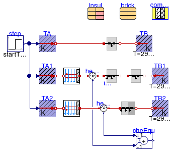
This example illustrates modeling of multi-layer materials. It also tests if the
multi-layer material computes the same heat transfer with its boundary condition
as two instances of a single layer material.
The insulation is computed in steady-state, whereas the brick is computed using transient
heat conduction.
The cheEqu block computes the difference between the heat fluxes,
which should be equal except for the numerical approximation error of the solver.
Extends from Modelica.Icons.Example (Icon for runnable examples).
Parameters
Modelica definition
model ConductorSteadyStateTransient
extends Modelica.Icons.Example;
parameter Buildings.HeatTransfer.Data.Solids.Brick brick(x=0.12, nStaRef=4);
parameter Buildings.HeatTransfer.Data.Solids.InsulationBoard insul(
x=0.05,
c=0,
nStaRef=3) ;
parameter Buildings.HeatTransfer.Data.OpaqueConstructions.Generic composite(nLay=2, material=
{insul,brick});
Buildings.HeatTransfer.Conduction.MultiLayer conMul(
A=2, layers=composite,
stateAtSurface_b=false);
Buildings.HeatTransfer.Conduction.SingleLayer con(
A=2, material=brick,
stateAtSurface_a=false,
stateAtSurface_b=false);
Buildings.HeatTransfer.Sources.FixedTemperature TB(T=293.15);
Buildings.HeatTransfer.Sources.PrescribedTemperature TA;
Modelica.Blocks.Sources.Step step(
height=10,
offset=293.15,
startTime=3600);
Buildings.HeatTransfer.Conduction.SingleLayer con1(
A=2, material=insul,
stateAtSurface_b=false);
Buildings.HeatTransfer.Sources.FixedTemperature TB1(T=293.15);
Buildings.HeatTransfer.Sources.PrescribedTemperature TA1;
Buildings.HeatTransfer.Conduction.SingleLayer con2(
A=2, material=brick,
stateAtSurface_b=false,
stateAtSurface_a=false);
Buildings.HeatTransfer.Sources.PrescribedTemperature TA2;
Buildings.HeatTransfer.Sources.FixedTemperature TB2(T=293.15);
Modelica.Thermal.HeatTransfer.Sensors.HeatFlowSensor heaFlo1;
Modelica.Thermal.HeatTransfer.Sensors.HeatFlowSensor heaFlo2;
Modelica.Blocks.Math.Add cheEqu(k2=-1) ;
Buildings.HeatTransfer.Convection.Interior conv1(A=2, til=Buildings.Types.Tilt.Wall)
;
Buildings.HeatTransfer.Convection.Interior conv2(A=2, til=Buildings.Types.Tilt.Wall)
;
equation
connect(con.port_b, TB.port);
connect(step.y, TA.T);
connect(step.y, TA1.T);
connect(con1.port_b, con2.port_a);
connect(con2.port_b, TB1.port);
connect(TA2.T, step.y);
connect(heaFlo1.port_b, con1.port_a);
connect(cheEqu.u1, heaFlo2.Q_flow);
connect(cheEqu.u2, heaFlo1.Q_flow);
connect(TA.port, con.port_a);
connect(conMul.port_b, TB2.port);
connect(conMul.port_a, heaFlo2.port_b);
connect(TA1.port, conv1.fluid);
connect(conv1.solid, heaFlo1.port_a);
connect(TA2.port, conv2.fluid);
connect(conv2.solid, heaFlo2.port_a);
end ConductorSteadyStateTransient;
Test model for heat conductor
Information
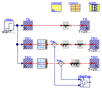
This example illustrates modeling of multi-layer materials. It also tests if the
multi-layer material computes the same heat transfer with its boundary condition
as two instances of a single layer material.
The insulation and the brick are computed using transient heat conduction.
The cheEqu block computes the difference between the heat fluxes,
which should be equal except for the numerical approximation error of the solver.
Extends from Modelica.Icons.Example (Icon for runnable examples).
Parameters
Modelica definition
model ConductorStepResponse
extends Modelica.Icons.Example;
parameter Buildings.HeatTransfer.Data.Solids.Concrete concrete(x=0.12, nStaRef=4);
parameter Buildings.HeatTransfer.Data.Resistances.Carpet carpet ;
parameter Buildings.HeatTransfer.Data.OpaqueConstructions.Generic composite(
nLay=2,
material={carpet,concrete});
Buildings.HeatTransfer.Conduction.MultiLayer conMul(
A=2, layers=composite,
stateAtSurface_b=false);
Buildings.HeatTransfer.Conduction.SingleLayer con(
A=2, material=carpet,
stateAtSurface_a=false,
stateAtSurface_b=false);
Buildings.HeatTransfer.Sources.FixedTemperature TB(T=293.15);
Buildings.HeatTransfer.Sources.PrescribedTemperature TA;
Modelica.Blocks.Sources.Step step(
height=10,
offset=293.15,
startTime=3600);
Buildings.HeatTransfer.Conduction.SingleLayer con1(
A=2, material=carpet,
stateAtSurface_b=false);
Buildings.HeatTransfer.Sources.FixedTemperature TB1( T=293.15);
Buildings.HeatTransfer.Sources.PrescribedTemperature TA1;
Buildings.HeatTransfer.Conduction.SingleLayer con2(
A=2, material=concrete,
stateAtSurface_b=false,
stateAtSurface_a=false);
Buildings.HeatTransfer.Sources.PrescribedTemperature TA2;
Buildings.HeatTransfer.Sources.FixedTemperature TB2( T=293.15);
Modelica.Thermal.HeatTransfer.Sensors.HeatFlowSensor heaFlo1;
Modelica.Thermal.HeatTransfer.Sensors.HeatFlowSensor heaFlo2;
Modelica.Blocks.Math.Add cheEqu(k2=-1) ;
Buildings.HeatTransfer.Convection.Interior conv1(
A=2, til=Buildings.Types.Tilt.Wall)
;
Buildings.HeatTransfer.Convection.Interior conv2(
A=2, til=Buildings.Types.Tilt.Wall)
;
equation
connect(con.port_b,TB. port);
connect(step.y,TA. T);
connect(step.y,TA1. T);
connect(con1.port_b,con2. port_a);
connect(con2.port_b,TB1. port);
connect(TA2.T,step. y);
connect(heaFlo1.port_b,con1. port_a);
connect(cheEqu.u1, heaFlo2.Q_flow);
connect(cheEqu.u2, heaFlo1.Q_flow);
connect(TA.port,con. port_a);
connect(conMul.port_b,TB2. port);
connect(conMul.port_a,heaFlo2. port_b);
connect(TA1.port, conv1.fluid);
connect(conv1.solid, heaFlo1.port_a);
connect(TA2.port, conv2.fluid);
connect(conv2.solid, heaFlo2.port_a);
end ConductorStepResponse;
 Buildings.HeatTransfer.Examples.ConductorInitialization
 Buildings.HeatTransfer.Examples.ConductorMultiLayer
 Buildings.HeatTransfer.Examples.ConductorMultiLayer2
 Buildings.HeatTransfer.Examples.ConductorMultiLayer3
 Buildings.HeatTransfer.Examples.ConductorSingleLayer
 Buildings.HeatTransfer.Examples.ConductorSingleLayer2
 Buildings.HeatTransfer.Examples.ConductorSingleLayerCylinder
 Buildings.HeatTransfer.Examples.ConductorSingleLayerPCM
 Buildings.HeatTransfer.Examples.ConductorSteadyStateTransient
 Buildings.HeatTransfer.Examples.ConductorStepResponse
