Package that contains the examples for balanced loads and step up transformer
Information
This package contains examples for the IEEE 4 nodes test validation
whith balanced load and step up in the voltage of the transformers.
Extends from Modelica.Icons.ExamplesPackage (Icon for packages containing runnable examples).
Package Content
| Name |
Description |
 DD DD
|
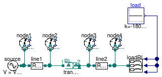
IEEE 4 node test feeder model with balanced load and D - D connection (step up) |
 DY DY
|
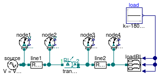
IEEE 4 node test feeder model with balanced load and D - Y connection (step up) |
 YD YD
|
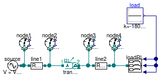
IEEE 4 node test feeder model with balanced load and Y - D connection (step up) |
 YY YY
|
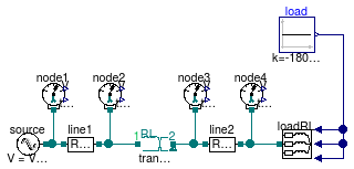
IEEE 4 node test feeder model with balanced load and Y - Y connection (step up) |
IEEE 4 node test feeder model with balanced load and D - D connection (step up)

Information
IEEE 4 nodes validation test case with the following characteristics
- balanced load,
- power consumption on each phase P1,2,3 = 1800 kW
- power factor on each phase cosφ1,2,3 = 0.9
- voltage step-up transformer (VPri=12.47 kV,
VSec = 24.9kV),
- D-D transformer
Extends from Buildings.Electrical.AC.ThreePhasesUnbalanced.Validation.IEEETests.Test4NodesFeeder.BaseClasses.IEEE4 (Base model of the IEEE 4 nodes test feeder).
Parameters
| Type | Name | Default | Description |
|---|
| Voltage | VLL_side1 | 12.47e3 | Voltage line to line side 1 [V] |
| Voltage | VLL_side2 | 24.9e3 | Voltage line to line side 2 [V] |
| ApparentPower | VARbase | 6000e3 | Base VA power of the transformer [VA] |
| Boolean | line1_use_Z_y | false | Choose between Zy or Zd impedance matrix for line 1 |
| Boolean | line2_use_Z_y | false | Choose between Zy or Zd impedance matrix for line 2 |
| Voltage | V2_ref[3] | {12361,12372,12348} | Reference RMS voltage node 2 - IEEE results [V] |
| Voltage | V3_ref[3] | {23723,23746,23698} | Reference RMS voltage node 3 - IEEE results [V] |
| Voltage | V4_ref[3] | {23657,23688,23625} | Reference RMS voltage node 4 - IEEE results [V] |
| Angle | Theta2_ref[3] | Modelica.Constants.pi/180.0*... | Reference voltage phase angle node 2 - IEEE results [rad] |
| Angle | Theta3_ref[3] | Modelica.Constants.pi/180.0*... | Reference voltage phase angle node 3 - IEEE results [rad] |
| Angle | Theta4_ref[3] | Modelica.Constants.pi/180.0*... | Reference voltage phase angle node 4 - IEEE results [rad] |
Modelica definition
model DD
"IEEE 4 node test feeder model with balanced load and D - D connection (step up)"
extends Buildings.Electrical.AC.ThreePhasesUnbalanced.Validation.IEEETests.Test4NodesFeeder.BaseClasses.IEEE4
(
final line1_use_Z_y=false,
final line2_use_Z_y=false,
redeclare Buildings.Electrical.AC.ThreePhasesUnbalanced.Sensors.ProbeDelta
node1,
redeclare Buildings.Electrical.AC.ThreePhasesUnbalanced.Sensors.ProbeDelta
node2,
redeclare Buildings.Electrical.AC.ThreePhasesUnbalanced.Sensors.ProbeDelta
node3,
redeclare Buildings.Electrical.AC.ThreePhasesUnbalanced.Sensors.ProbeDelta
node4,
final VLL_side1=12.47e3,
final VLL_side2=24.9e3,
final VARbase=6000e3,
final V2_ref={12361,12372,12348},
final V3_ref={23723,23746,23698},
final V4_ref={23657,23688,23625},
final Theta2_ref=Modelica.Constants.pi/180.0*{29.7,-90.4,149.6},
final Theta3_ref=Modelica.Constants.pi/180.0*{26.7,-93.4,146.6},
final Theta4_ref=Modelica.Constants.pi/180.0*{26.6,-93.6,146.5},
loadRL(use_pf_in=false, loadConn=Buildings.Electrical.Types.LoadConnection.wye_to_delta));
Modelica.Blocks.Sources.Constant load(k=-1800e3);
Buildings.Electrical.AC.ThreePhasesUnbalanced.Conversion.ACACTransformerDD
transformer(
VHigh=VLL_side1,
VLow=VLL_side2,
XoverR=6,
Zperc=
sqrt(0.01^2 + 0.06^2),
VABase=VARbase);
equation
connect(load.y, loadRL.Pow1);
connect(load.y, loadRL.Pow2);
connect(load.y, loadRL.Pow3);
connect(line1.terminal_p, transformer.terminal_n);
connect(transformer.terminal_p, line2.terminal_n);
connect(node1.term, line1.terminal_n);
connect(node2.term, transformer.terminal_n);
connect(node3.term, line2.terminal_n);
connect(node4.term, loadRL.terminal);
end DD;
IEEE 4 node test feeder model with balanced load and D - Y connection (step up)

Information
IEEE 4 nodes validation test case with the following characteristics
- balanced load,
- power consumption on each phase P1,2,3 = 1800 kW
- power factor on each phase cosφ1,2,3 = 0.9
- voltage step-up transformer (VPri=12.47 kV,
VSec = 24.9kV),
- D-Y transformer
Extends from Buildings.Electrical.AC.ThreePhasesUnbalanced.Validation.IEEETests.Test4NodesFeeder.BaseClasses.IEEE4 (Base model of the IEEE 4 nodes test feeder).
Parameters
| Type | Name | Default | Description |
|---|
| Voltage | VLL_side1 | 12.47e3 | Voltage line to line side 1 [V] |
| Voltage | VLL_side2 | 24.9e3 | Voltage line to line side 2 [V] |
| ApparentPower | VARbase | 6000e3 | Base VA power of the transformer [VA] |
| Boolean | line1_use_Z_y | false | Choose between Zy or Zd impedance matrix for line 1 |
| Boolean | line2_use_Z_y | true | Choose between Zy or Zd impedance matrix for line 2 |
| Voltage | V2_ref[3] | {12361,12372,12348} | Reference RMS voltage node 2 - IEEE results [V] |
| Voltage | V3_ref[3] | {13697,13710,13681} | Reference RMS voltage node 3 - IEEE results [V] |
| Voltage | V4_ref[3] | {13653,13678,13644} | Reference RMS voltage node 4 - IEEE results [V] |
| Angle | Theta2_ref[3] | Modelica.Constants.pi/180.0*... | Reference voltage phase angle node 2 - IEEE results [rad] |
| Angle | Theta3_ref[3] | Modelica.Constants.pi/180.0*... | Reference voltage phase angle node 3 - IEEE results [rad] |
| Angle | Theta4_ref[3] | Modelica.Constants.pi/180.0*... | Reference voltage phase angle node 4 - IEEE results [rad] |
Modelica definition
model DY
"IEEE 4 node test feeder model with balanced load and D - Y connection (step up)"
extends Buildings.Electrical.AC.ThreePhasesUnbalanced.Validation.IEEETests.Test4NodesFeeder.BaseClasses.IEEE4
(
final line1_use_Z_y=false,
final line2_use_Z_y=true,
redeclare Buildings.Electrical.AC.ThreePhasesUnbalanced.Sensors.ProbeDelta
node1,
redeclare Buildings.Electrical.AC.ThreePhasesUnbalanced.Sensors.ProbeDelta
node2,
redeclare Buildings.Electrical.AC.ThreePhasesUnbalanced.Sensors.ProbeWye
node3,
redeclare Buildings.Electrical.AC.ThreePhasesUnbalanced.Sensors.ProbeWye
node4,
final VLL_side1=12.47e3,
final VLL_side2=24.9e3,
final VARbase=6000e3,
final V2_ref={12361,12372,12348},
final V3_ref={13697,13710,13681},
final V4_ref={13653,13678,13644},
final Theta2_ref=Modelica.Constants.pi/180.0*{29.7,-90.4,149.6},
final Theta3_ref=Modelica.Constants.pi/180.0*{26.7,-93.4,146.6},
final Theta4_ref=Modelica.Constants.pi/180.0*{26.6,-93.5,146.5},
loadRL(use_pf_in=false));
Modelica.Blocks.Sources.Constant load(k=-1800e3);
Buildings.Electrical.AC.ThreePhasesUnbalanced.Conversion.ACACTransformerStepUpDY
transformer(
VHigh=VLL_side1,
VLow=VLL_side2,
XoverR=6,
Zperc=
sqrt(0.01^2 + 0.06^2),
VABase=VARbase);
equation
connect(load.y, loadRL.Pow1);
connect(load.y, loadRL.Pow2);
connect(load.y, loadRL.Pow3);
connect(line1.terminal_p, transformer.terminal_n);
connect(transformer.terminal_p, line2.terminal_n);
connect(node1.term, line1.terminal_n);
connect(node2.term, transformer.terminal_n);
connect(node3.term, line2.terminal_n);
connect(node4.term, loadRL.terminal);
end DY;
IEEE 4 node test feeder model with balanced load and Y - D connection (step up)

Information
IEEE 4 nodes validation test case with the following characteristics
- balanced load,
- power consumption on each phase P1,2,3 = 1800 kW
- power factor on each phase cosφ1,2,3 = 0.9
- voltage step-up transformer (VPri=12.47 kV,
VSec = 24.9kV),
- Y-D transformer
Extends from Buildings.Electrical.AC.ThreePhasesUnbalanced.Validation.IEEETests.Test4NodesFeeder.BaseClasses.IEEE4 (Base model of the IEEE 4 nodes test feeder).
Parameters
| Type | Name | Default | Description |
|---|
| Voltage | VLL_side1 | 12.47e3 | Voltage line to line side 1 [V] |
| Voltage | VLL_side2 | 24.9e3 | Voltage line to line side 2 [V] |
| ApparentPower | VARbase | 6000e3 | Base VA power of the transformer [VA] |
| Boolean | line1_use_Z_y | true | Choose between Zy or Zd impedance matrix for line 1 |
| Boolean | line2_use_Z_y | false | Choose between Zy or Zd impedance matrix for line 2 |
| Voltage | V2_ref[3] | {7128,7145,7137} | Reference RMS voltage node 2 - IEEE results [V] |
| Voltage | V3_ref[3] | {23746,23722,23698} | Reference RMS voltage node 3 - IEEE results [V] |
| Voltage | V4_ref[3] | {23680,23663,23625} | Reference RMS voltage node 4 - IEEE results [V] |
| Angle | Theta2_ref[3] | Modelica.Constants.pi/180.0*... | Reference voltage phase angle node 2 - IEEE results [rad] |
| Angle | Theta3_ref[3] | Modelica.Constants.pi/180.0*... | Reference voltage phase angle node 3 - IEEE results [rad] |
| Angle | Theta4_ref[3] | Modelica.Constants.pi/180.0*... | Reference voltage phase angle node 4 - IEEE results [rad] |
Modelica definition
model YD
"IEEE 4 node test feeder model with balanced load and Y - D connection (step up)"
extends Buildings.Electrical.AC.ThreePhasesUnbalanced.Validation.IEEETests.Test4NodesFeeder.BaseClasses.IEEE4
(
final line1_use_Z_y=true,
final line2_use_Z_y=false,
redeclare Buildings.Electrical.AC.ThreePhasesUnbalanced.Sensors.ProbeWye
node1,
redeclare Buildings.Electrical.AC.ThreePhasesUnbalanced.Sensors.ProbeWye
node2,
redeclare Buildings.Electrical.AC.ThreePhasesUnbalanced.Sensors.ProbeDelta
node3,
redeclare Buildings.Electrical.AC.ThreePhasesUnbalanced.Sensors.ProbeDelta
node4,
final VLL_side1=12.47e3,
final VLL_side2=24.9e3,
final VARbase=6000e3,
final V2_ref={7128,7145,7137},
final V3_ref={23746,23722,23698},
final V4_ref={23680,23663,23625},
final Theta2_ref=Modelica.Constants.pi/180.0*{-0.3,-120.3,119.6},
final Theta3_ref=Modelica.Constants.pi/180.0*{56.7,-63.4,176.7},
final Theta4_ref=Modelica.Constants.pi/180.0*{56.6,-63.6,176.5},
loadRL(use_pf_in=false, loadConn=Buildings.Electrical.Types.LoadConnection.wye_to_delta));
Modelica.Blocks.Sources.Constant load(k=-1800e3);
Buildings.Electrical.AC.ThreePhasesUnbalanced.Conversion.ACACTransformerStepUpYD
transformer(
VHigh=VLL_side1,
VLow=VLL_side2,
XoverR=6,
Zperc=
sqrt(0.01^2 + 0.06^2),
VABase=VARbase);
equation
connect(load.y, loadRL.Pow1);
connect(load.y, loadRL.Pow2);
connect(load.y, loadRL.Pow3);
connect(line1.terminal_p, transformer.terminal_n);
connect(transformer.terminal_p, line2.terminal_n);
connect(node1.term, line1.terminal_n);
connect(node2.term, transformer.terminal_n);
connect(node3.term, line2.terminal_n);
connect(node4.term, loadRL.terminal);
end YD;
IEEE 4 node test feeder model with balanced load and Y - Y connection (step up)

Information
IEEE 4 nodes validation test case with the following characteristics
- balanced load,
- power consumption on each phase P1,2,3 = 1800 kW
- power factor on each phase cosφ1,2,3 = 0.9
- voltage step-up transformer (VPri=12.47 kV,
VSec = 24.9kV),
- Y-Y transformer
Extends from Buildings.Electrical.AC.ThreePhasesUnbalanced.Validation.IEEETests.Test4NodesFeeder.BaseClasses.IEEE4 (Base model of the IEEE 4 nodes test feeder).
Parameters
| Type | Name | Default | Description |
|---|
| Voltage | VLL_side1 | 12.47e3 | Voltage line to line side 1 [V] |
| Voltage | VLL_side2 | 24.9e3 | Voltage line to line side 2 [V] |
| ApparentPower | VARbase | 6000e3 | Base VA power of the transformer [VA] |
| Boolean | line1_use_Z_y | true | Choose between Zy or Zd impedance matrix for line 1 |
| Boolean | line2_use_Z_y | true | Choose between Zy or Zd impedance matrix for line 2 |
| Voltage | V2_ref[3] | {7126,7145,7137} | Reference RMS voltage node 2 - IEEE results [V] |
| Voltage | V3_ref[3] | {13675,13715,13698} | Reference RMS voltage node 3 - IEEE results [V] |
| Voltage | V4_ref[3] | {13631,13682,13661} | Reference RMS voltage node 4 - IEEE results [V] |
| Angle | Theta2_ref[3] | Modelica.Constants.pi/180.0*... | Reference voltage phase angle node 2 - IEEE results [rad] |
| Angle | Theta3_ref[3] | Modelica.Constants.pi/180.0*... | Reference voltage phase angle node 3 - IEEE results [rad] |
| Angle | Theta4_ref[3] | Modelica.Constants.pi/180.0*... | Reference voltage phase angle node 4 - IEEE results [rad] |
Modelica definition
model YY
"IEEE 4 node test feeder model with balanced load and Y - Y connection (step up)"
extends Buildings.Electrical.AC.ThreePhasesUnbalanced.Validation.IEEETests.Test4NodesFeeder.BaseClasses.IEEE4
(
final line1_use_Z_y=true,
final line2_use_Z_y=true,
redeclare Buildings.Electrical.AC.ThreePhasesUnbalanced.Sensors.ProbeWye
node1,
redeclare Buildings.Electrical.AC.ThreePhasesUnbalanced.Sensors.ProbeWye
node2,
redeclare Buildings.Electrical.AC.ThreePhasesUnbalanced.Sensors.ProbeWye
node3,
redeclare Buildings.Electrical.AC.ThreePhasesUnbalanced.Sensors.ProbeWye
node4,
final VLL_side1=12.47e3,
final VLL_side2=24.9e3,
final VARbase=6000e3,
final V2_ref={7126,7145,7137},
final V3_ref={13675,13715,13698},
final V4_ref={13631,13682,13661},
final Theta2_ref=Modelica.Constants.pi/180.0*{-0.3,-120.4,119.6},
final Theta3_ref=Modelica.Constants.pi/180.0*{-3.3,-123.4,116.6},
final Theta4_ref=Modelica.Constants.pi/180.0*{-3.5,-123.5,116.5},
loadRL(use_pf_in=false));
Modelica.Blocks.Sources.Constant load(k=-1800e3);
Buildings.Electrical.AC.ThreePhasesUnbalanced.Conversion.ACACTransformer
transformer(
VHigh=VLL_side1,
VLow=VLL_side2,
XoverR=6,
Zperc=
sqrt(0.01^2 + 0.06^2),
VABase=VARbase);
equation
connect(load.y, loadRL.Pow1);
connect(load.y, loadRL.Pow2);
connect(load.y, loadRL.Pow3);
connect(line1.terminal_p, transformer.terminal_n);
connect(transformer.terminal_p, line2.terminal_n);
connect(node1.term, source.terminal);
connect(node2.term, transformer.terminal_n);
connect(node3.term, line2.terminal_n);
connect(node4.term, loadRL.terminal);
end YY;
Automatically generated Mon Jul 13 14:23:28 2015.


 Buildings.Electrical.AC.ThreePhasesUnbalanced.Validation.IEEETests.Test4NodesFeeder.BalancedStepUp.DD
 Buildings.Electrical.AC.ThreePhasesUnbalanced.Validation.IEEETests.Test4NodesFeeder.BalancedStepUp.DY
 Buildings.Electrical.AC.ThreePhasesUnbalanced.Validation.IEEETests.Test4NodesFeeder.BalancedStepUp.YD
 Buildings.Electrical.AC.ThreePhasesUnbalanced.Validation.IEEETests.Test4NodesFeeder.BalancedStepUp.YY