Buildings.Fluid.Geothermal.ZonedBorefields.UsersGuide
User's Guide
Information
This package contains borefield models for the simulation of zoned borehole thermal energy storage systems. These models can simulate any arbitrary configuration of vertical boreholes with equal lengths with both short and long-term accuracy with an aggregation method to speed up the calculations of the ground heat transfer. Examples of how to use the borefield models and validation cases can be found in Buildings.Fluid.Geothermal.ZonedBorefields.Examples and Buildings.Fluid.Geothermal.ZonedBorefields.Validation, respectively.
The major features and configurations are as follows:
- User-defined borefield characteristics and geometry (borehole radius, pipe radius, shank spacing, etc.), including single U-tube, double U-tube in parallel and double U-tube in series configurations.
- The resistances Rb and Ra are either automatically calculated using the multipole method, or the resistance Rb can be directly provided by the user. In this case, the resistances Rb and Ra are still evaluated internally, but their values are weighted so that the borehole resistance matches the specified value.
- User-defined vertical discretization of boreholes are supported.
- Borefields can consist of one or many boreholes. Each borehole can be positioned at an arbitrary position in the field using cartesian coordinates.
- The resolution and precision of the load aggregation method for the ground heat transfer can be adapted.
- The thermal response of the ground heat transfer is stored locally to avoid having to recalculate it for future simulations with the same borefield configuration.
-
Pressure losses are calculated if the
dp_nominalparameter is set to a non-zero value.
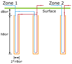
The model allows the simulation of multiple zones of boreholes within the same
borefield. All boreholes in a zone have the same length
hBor, the same radius rBor, and are buried at the
same depth dBor below the ground surface (also known as the
inactive borehole length).
How to use the borefield models
Borefield data record
Most of the parameter values of the model are contained in the record called borFieDat.
This record is composed of three subrecords:
filDat contains the thermal characteristics of the borehole filling material,
soiDat contains the thermal characteristics of the surrounding soil,
and conDat contains all others parameters, namely parameters
defining the configuration of the borefield.
The structure and default values of the record are in the package:
Buildings.Fluid.Geothermal.ZonedBorefields.Data.
The borFieDat record
can be found in the
Buildings.Fluid.Geothermal.ZonedBorefields.Data.Borefield subpackage therein.
Examples of the subrecords conDat, filDat and soiDat
can be found in
Buildings.Fluid.Geothermal.ZonedBorefields.Data.Configuration,
Buildings.Fluid.Geothermal.ZonedBorefields.Data.Filling and
Buildings.Fluid.Geothermal.ZonedBorefields.Data.Soil, respectively.
It is important to make sure that the borCon parameter within
the conDat subrecord is compatible with the chosen borefield model.
For example, if a double U-tube
borefield model is chosen, the borCon parameter could be set
to both a parallel double U-tube configuration and a double U-tube configuration in series,
but could not be set to a single U-tube configuration. An incompatible borehole
configuration will stop the simulation.
Ground heat transfer parameters
Other than the parameters contained in the borFieDat record,
the borefield models have other parameters which can be modified by the user.
The tLoaAgg parameter is the time resolution of the load aggregation
for the calculation of the ground heat transfer. It represents the
frequency at which the load aggregation procedure is performed in the simulation.
Therefore, smaller values of tLoaAgg will improve
the accuracy of the model, at the cost of increased simulation times
due to a higher number of events occuring in the simulation. While a default value
is provided for this parameter, it is advisable to ensure that it is lower
than a fraction (e.g. half) of the time required for the fluid to completely circulate
through the borefield,
as increasing the value of tLoaAgg beyond this
will result in non-physical borehole wall temperatures.
The nCel parameter also affects the accuracy and simulation time
of the ground heat transfer calculations. As this parameter sets the number
of consecutive equal-size aggregation cells before increasing the size of cells,
increasing its value will result in less load aggregation, which will increase
accuracy at the cost of computation time. On the other hand,
decreasing the value of nCel (down to a minimum of 1)
will decrease accuracy but improve
computation time. The default value is chosen as a compromise between the two.
Further information on the tLoaAgg and nCel parameters can
be found in the documentation of
Buildings.Fluid.Geothermal.ZonedBorefields.BaseClasses.HeatTransfer.GroundTemperatureResponse.
Other parameters
Other parameters which can be modified include the dynamics, initial conditions,
and further information regarding the fluid flow, for example whether the flow is reversible.
It is worth noting that regardless of the energyDynamics chosen,
the steadyState parameter of the borehole filling material can be set to true
to remove the effect of the thermal capacitance
of the filling material in the borehole(s).
The nSeg parameter specifies the number of segments for the vertical discretization
of the borehole(s).
Further information on this discretization can be found in the "Model description" section below.
Fluid flow
In every zone, all boreholes are connected in parallel. Models that instantiate this borefield model need to provide the
pressure drop or mass flow rate that is needed to distribute the flow to the different zones. Each zone of a borefield is connected
between its port_a and port_b, e.g., flow that enters port_a[1] leaves at port_b[1].
Zones that operate in series can be configured by connecting the fluid
ports of the respective zones. For example, suppose the borefield has the instance name borFie. Then,
the connect statement
connect(borFie.port_b[1], borFie.port_a[2]);
connects the outlet of the first zone to the inlet of the second zone.
Model description
The borefield models rely on the following key assumptions:
- The thermal properties of the soil (conductivity and diffusivity) are constant, homogenous and isotropic.
- The conductivity, capacitance and density of the grout and pipe material are constant, homogenous and isotropic.
- There is no heat extraction or injection prior to the simulation start.
- All of the boreholes in the borefield have uniform dimensions (including the pipe dimensions).
- Inside the boreholes, the non-advective heat transfer is only in the radial direction.
The borefield models are constructed in two main parts: the borehole(s) and the ground heat transfer.
The former is modeled as a vertical discretization of borehole segments, where a uniform temperature increase or decrease
(due to heat injection or extraction) is superimposed to the far-field ground temperature to obtain the borehole wall
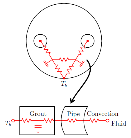
temperature. The thermal effects of the circulating fluid (including the convection resistance),
of the pipes and of the filling material are all taken into consideration, which allows modeling
short-term thermal effects in the borehole. The borehole segments do not take into account axial effects,
thus only radial (horizontal) effects are considered within the borehole(s). The thermal
behavior between the pipes and borehole wall are modeled as a resistance-capacitance network, with
the grout capacitance being split in the number of pipes present in a borehole section.
The capacitance is only present if the steadyState parameter of the borehole filling material
is set to false.
The figure below shows an example for a borehole section within a single U-tube configuration.
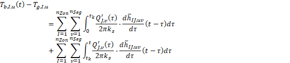
The second main part of the borefield models is the ground heat transfer. The heat transfer in the ground is modeled analytically as a superposition of convolution integrals between the heat flux at each of the borehole segments and the borefield's thermal response factor.
The model uses a load aggregation technique to reduce the time required to calculate the borehole wall temperature changes resulting from heat injection or extraction.
The ground heat transfer takes into account both the borehole axial effects and the borehole radial effects which are a result of its cylindrical geometry. Further information on the ground heat transfer model and the thermal temperature response calculations can be found in Buildings.Fluid.Geothermal.ZonedBorefields.BaseClasses.HeatTransfer.GroundTemperatureResponse.
Calculation times
The calculation times for both the initialization and the time integration depends on the square of the number of zones and the number of segments. The number of boreholes should only weakly impact on the initialization time.
Extends from Modelica.Icons.Information (Icon for general information packages).