Collection of models that illustrate model use and test models
Information
This packages contains examples for Reduced Order Model applications.
Extends from Modelica.Icons.ExamplesPackage (Icon for packages containing runnable examples).
Package Content
| Name |
Description |
 SimpleRoomFourElements SimpleRoomFourElements
|
Illustrates the use of a thermal zone with four heat conduction elements |
 SimpleRoomFourElementsTraceSubstance SimpleRoomFourElementsTraceSubstance
|
Illustrates the use of a thermal zone considering a trace substance |
 SimpleRoomOneElement SimpleRoomOneElement
|
Illustrates the use of a thermal zone with one heat conduction element |
 SimpleRoomThreeElements SimpleRoomThreeElements
|
Illustrates the use of a thermal zone with three heat conduction elements |
 SimpleRoomTwoElements SimpleRoomTwoElements
|
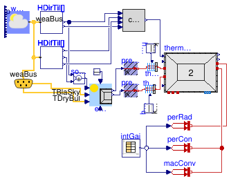
Illustrates the use of a thermal zone with two heat conduction elements |
 SimpleRoomTwoElementsNonConstantTGround SimpleRoomTwoElementsNonConstantTGround
|
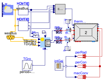
Illustrates the use of non-constant ground temperature for equivalent air temperature calculation |
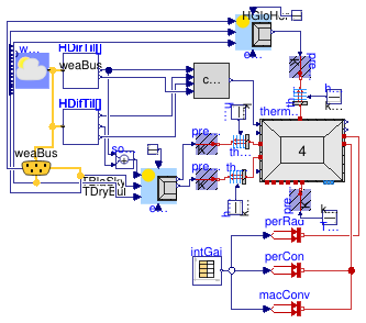
Illustrates the use of a thermal zone with four heat conduction elements
Information
This example shows the application of
Buildings.ThermalZones.ReducedOrder.RC.FourElements
in combination with
Buildings.ThermalZones.ReducedOrder.EquivalentAirTemperature.VDI6007WithWindow
and
Buildings.ThermalZones.ReducedOrder.SolarGain.CorrectionGDoublePane.
Solar radiation on tilted surface is calculated using models of
Buildings. The thermal zone is a simple room defined in Guideline
VDI 6007 Part 1 (VDI, 2012). All models, parameters and inputs
except sunblinds, separate handling of heat transfer through
windows, an extra wall element for ground floor (with additional
area), an extra wall element for roof (with additional area) and
solar radiation are similar to the ones defined for the
guideline's test room. For solar radiation, the example
relies on the standard weather file in Buildings.
The idea of the example is to show a typical application of
all sub-models and to use the example in unit tests. The results
are reasonable, but not related to any real use case or measurement
data.
References
VDI. German Association of Engineers Guideline VDI
6007-1 March 2012. Calculation of transient thermal response of
rooms and buildings - modelling of rooms.
Extends from Modelica.Icons.Example (Icon for runnable examples).
Connectors
| Type | Name | Description |
|---|
| Bus | weaBus | Weather data bus |
Modelica definition
model SimpleRoomFourElements
extends Modelica.Icons.Example;
BoundaryConditions.WeatherData.ReaderTMY3 weaDat(
calTSky=Buildings.BoundaryConditions.Types.SkyTemperatureCalculation.HorizontalRadiation,
computeWetBulbTemperature=false,
filNam=
Modelica.Utilities.Files.loadResource("modelica://Buildings/Resources/weatherdata/USA_CA_San.Francisco.Intl.AP.724940_TMY3.mos"))
;
BoundaryConditions.SolarIrradiation.DiffusePerez HDifTil[2](
each outSkyCon=true,
each outGroCon=true,
each til=1.5707963267949,
azi={3.1415926535898,4.7123889803847})
;
BoundaryConditions.SolarIrradiation.DirectTiltedSurface HDirTil[2](
each til=1.5707963267949,
azi={3.1415926535898,4.7123889803847})
;
SolarGain.CorrectionGDoublePane corGDouPan(UWin=2.1, n=2)
;
RC.FourElements thermalZoneFourElements(
VAir=52.5,
hConExt=2.7,
hConWin=2.7,
gWin=1,
ratioWinConRad=0.09,
nExt=1,
RExt={0.00331421908725},
CExt={5259932.23},
hRad=5,
AInt=60.5,
hConInt=2.12,
nInt=1,
RInt={0.000668895639141},
CInt={12391363.86},
RWin=0.01642857143,
RExtRem=0.1265217391,
AFloor=11.5,
hConFloor=2.7,
nFloor=1,
RFloor={0.00331421908725},
RFloorRem=0.1265217391,
CFloor={5259932.23},
ARoof=11.5,
hConRoof=2.7,
nRoof=1,
RRoof={0.00331421908725},
RRoofRem=0.1265217391,
CRoof={5259932.23},
nOrientations=2,
AWin={7,7},
ATransparent={7,7},
AExt={3.5,8},
redeclare replaceable package Medium =
Modelica.Media.Air.SimpleAir,
energyDynamics=Modelica.Fluid.Types.Dynamics.FixedInitial,
extWallRC(thermCapExt(
each der_T(fixed=true))),
intWallRC(thermCapInt(
each der_T(fixed=true))),
floorRC(thermCapExt(
each der_T(fixed=true))),
T_start=295.15,
roofRC(thermCapExt(
each der_T(fixed=true)))) ;
EquivalentAirTemperature.VDI6007WithWindow eqAirTemp(
wfGro=0,
withLongwave=true,
aExt=0.7,
hConWallOut=20,
hRad=5,
hConWinOut=20,
n=2,
wfWall={0.3043478260869566,0.6956521739130435},
wfWin={0.5,0.5},
TGro=285.15) ;
Modelica.Blocks.Math.Add solRad[2]
;
Buildings.HeatTransfer.Sources.PrescribedTemperature preTem
;
Buildings.HeatTransfer.Sources.PrescribedTemperature preTem1
;
Modelica.Thermal.HeatTransfer.Components.Convection theConWin
;
Modelica.Thermal.HeatTransfer.Components.Convection theConWall
;
Modelica.Thermal.HeatTransfer.Sources.PrescribedHeatFlow perRad
;
Modelica.Thermal.HeatTransfer.Sources.PrescribedHeatFlow perCon
;
Modelica.Blocks.Sources.CombiTimeTable intGai(
table=[0,0,0,0; 3600,0,0,0; 7200,0,0,0; 10800,0,0,0; 14400,0,0,0; 18000,0,0,
0; 21600,0,0,0; 25200,0,0,0; 25200,80,80,200; 28800,80,80,200; 32400,80,
80,200; 36000,80,80,200; 39600,80,80,200; 43200,80,80,200; 46800,80,80,200;
50400,80,80,200; 54000,80,80,200; 57600,80,80,200; 61200,80,80,200; 61200,
0,0,0; 64800,0,0,0; 72000,0,0,0; 75600,0,0,0; 79200,0,0,0; 82800,0,0,0;
86400,0,0,0],
columns={2,3,4},
extrapolation=Modelica.Blocks.Types.Extrapolation.Periodic) ;
Modelica.Blocks.Sources.Constant const[2](
each k=0)
;
BoundaryConditions.WeatherData.Bus weaBus ;
Modelica.Thermal.HeatTransfer.Sources.PrescribedHeatFlow macConv
;
Modelica.Blocks.Sources.Constant hConWall(k=25*11.5)
;
Modelica.Blocks.Sources.Constant hConWin(k=20*14)
;
Buildings.HeatTransfer.Sources.PrescribedTemperature preTemFloor
;
Modelica.Blocks.Sources.Constant TSoil(k=283.15)
;
EquivalentAirTemperature.VDI6007 eqAirTempVDI(
aExt=0.7,
n=1,
wfWall={1},
wfWin={0},
wfGro=0,
hConWallOut=20,
hRad=5,
TGro=285.15) ;
Buildings.HeatTransfer.Sources.PrescribedTemperature preTemRoof
;
Modelica.Thermal.HeatTransfer.Components.Convection theConRoof
;
Modelica.Blocks.Sources.Constant hConRoof(k=25*11.5)
;
Modelica.Blocks.Sources.Constant const1(k=0)
;
equation
connect(eqAirTemp.TEqAirWin, preTem1.T);
connect(eqAirTemp.TEqAir, preTem.T);
connect(weaDat.weaBus, weaBus);
connect(weaBus.TDryBul, eqAirTemp.TDryBul);
connect(intGai.y[1], perRad.Q_flow);
connect(intGai.y[2], perCon.Q_flow);
connect(intGai.y[3], macConv.Q_flow);
connect(const.y, eqAirTemp.sunblind);
connect(HDifTil.HSkyDifTil, corGDouPan.HSkyDifTil);
connect(HDirTil.H, corGDouPan.HDirTil);
connect(HDirTil.H,solRad. u1);
connect(HDifTil.H,solRad. u2);
connect(HDifTil.HGroDifTil, corGDouPan.HGroDifTil);
connect(solRad.y, eqAirTemp.HSol);
connect(weaDat.weaBus, HDifTil[1].weaBus);
connect(weaDat.weaBus, HDifTil[2].weaBus);
connect(weaDat.weaBus, HDirTil[1].weaBus);
connect(weaDat.weaBus, HDirTil[2].weaBus);
connect(perRad.port, thermalZoneFourElements.intGainsRad);
connect(theConWin.solid, thermalZoneFourElements.window);
connect(preTem1.port, theConWin.fluid);
connect(thermalZoneFourElements.extWall, theConWall.solid);
connect(theConWall.fluid, preTem.port);
connect(hConWall.y, theConWall.Gc);
connect(hConWin.y, theConWin.Gc);
connect(weaBus.TBlaSky, eqAirTemp.TBlaSky);
connect(macConv.port, thermalZoneFourElements.intGainsConv);
connect(perCon.port, thermalZoneFourElements.intGainsConv);
connect(preTemFloor.port, thermalZoneFourElements.floor);
connect(TSoil.y, preTemFloor.T);
connect(preTemRoof.port, theConRoof.fluid);
connect(theConRoof.solid, thermalZoneFourElements.roof);
connect(eqAirTempVDI.TEqAir, preTemRoof.T);
connect(theConRoof.Gc, hConRoof.y);
connect(eqAirTempVDI.TDryBul, eqAirTemp.TDryBul);
connect(eqAirTempVDI.TBlaSky, eqAirTemp.TBlaSky);
connect(eqAirTempVDI.HSol[1], weaBus.HGloHor);
connect(HDirTil.inc, corGDouPan.inc);
connect(const1.y, eqAirTempVDI.sunblind[1]);
connect(corGDouPan.solarRadWinTrans, thermalZoneFourElements.solRad);
end SimpleRoomFourElements;
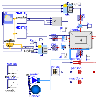
Illustrates the use of a thermal zone considering a trace substance
Information
This example shows the application of
Buildings.ThermalZones.ReducedOrder.RC.FourElements
considering a trace substance such as CO2
in combination with
Buildings.ThermalZones.ReducedOrder.EquivalentAirTemperature.VDI6007WithWindow
and
Buildings.ThermalZones.ReducedOrder.SolarGain.CorrectionGDoublePane.
Solar radiation on tilted surface is calculated using models of
Buildings. The thermal zone is a simple room defined in Guideline
VDI 6007 Part 1 (VDI, 2012).
The trace substance calculation is based on the CO2 emissions of 2 persons.
They stay in the thermal zone for 12 hours every 24 hours. The air exchange rate is 2 air changes per hour.
All further models, parameters and inputs
except sunblinds, separate handling of heat transfer through
windows, no wall element for internal walls and solar radiation
are similar to the ones defined for the guideline's test
room. For solar radiation, the example relies on the standard
weather file in Buildings.
The idea of the example is to show a typical application of all
sub-models and to use the example in unit tests. The results are
reasonable, but not related to any real use case or measurement
data.
References
VDI. German Association of Engineers Guideline VDI 6007-1
March 2012. Calculation of transient thermal response of rooms
and buildings - modelling of rooms.
Extends from Modelica.Icons.Example (Icon for runnable examples), Buildings.ThermalZones.ReducedOrder.Examples.SimpleRoomFourElements (Illustrates the use of a thermal zone with four heat conduction elements).
Parameters
| Type | Name | Default | Description |
|---|
| replaceable package Medium | Buildings.Media.Air (extraPr... | Medium model |
| Real | airChaRat | 2/3600 | Air change rate [1/s] |
Connectors
| Type | Name | Description |
|---|
| Bus | weaBus | Weather data bus |
| replaceable package Medium | Medium model |
Modelica definition
model SimpleRoomFourElementsTraceSubstance
extends Modelica.Icons.Example;
extends Buildings.ThermalZones.ReducedOrder.Examples.SimpleRoomFourElements(thermalZoneFourElements(
redeclare package Medium =
Medium,
use_C_flow=true,
nPorts=2));
replaceable package Medium =
Buildings.Media.Air (
extraPropertiesNames={"C_flow"}) ;
parameter Real airChaRat(
final unit="1/s") = 2/3600 ;
Modelica.Blocks.Sources.Pulse traSub(
amplitude=10.4*2*(28.949/44.01),
width=50,
period=86400,
offset=0) ;
Buildings.Fluid.Sources.MassFlowSource_T souAir(
redeclare package Medium =
Medium,
use_C_in=true,
m_flow=airChaRat*rho_default*thermalZoneFourElements.VAir,
nPorts=1) ;
Buildings.Fluid.Sources.Boundary_pT sinAir(
redeclare package Medium =
Medium,
C={400},
nPorts=1) ;
Modelica.Blocks.Sources.Ramp traSubAmb(
height=200,
duration(displayUnit="d") = 259200,
offset=200) ;
protected
final parameter Medium.ThermodynamicState state_default =
Medium.setState_pTX(
T=Medium.T_default,
p=Medium.p_default,
X=Medium.X_default[1:Medium.nXi]) ;
final parameter Modelica.Units.SI.Density rho_default=
Medium.density(state=
state_default) ;
equation
connect(traSub.y, thermalZoneFourElements.C_flow[1]);
connect(souAir.ports[1], thermalZoneFourElements.ports[1]);
connect(sinAir.ports[1], thermalZoneFourElements.ports[2]);
connect(traSubAmb.y, souAir.C_in[1]);
end SimpleRoomFourElementsTraceSubstance;
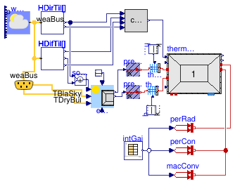
Illustrates the use of a thermal zone with one heat conduction element
Information
This example shows the application of
Buildings.ThermalZones.ReducedOrder.RC.OneElement
in combination with
Buildings.ThermalZones.ReducedOrder.EquivalentAirTemperature.VDI6007WithWindow
and
Buildings.ThermalZones.ReducedOrder.SolarGain.CorrectionGDoublePane.
Solar radiation on tilted surface is calculated using models of
Buildings. The thermal zone is a simple room defined in Guideline
VDI 6007 Part 1 (VDI, 2012). All models, parameters and inputs
except sunblinds, separate handling of heat transfer through
windows, no wall element for internal walls and solar radiation
are similar to the ones defined for the guideline's test
room. For solar radiation, the example relies on the standard
weather file in Buildings.
The idea of the example is to show a typical application of all
sub-models and to use the example in unit tests. The results are
reasonable, but not related to any real use case or measurement
data.
References
VDI. German Association of Engineers Guideline VDI 6007-1
March 2012. Calculation of transient thermal response of rooms
and buildings - modelling of rooms.
Extends from Modelica.Icons.Example (Icon for runnable examples).
Connectors
| Type | Name | Description |
|---|
| Bus | weaBus | Weather data bus |
Modelica definition
model SimpleRoomOneElement
extends Modelica.Icons.Example;
BoundaryConditions.WeatherData.ReaderTMY3 weaDat(
calTSky=Buildings.BoundaryConditions.Types.SkyTemperatureCalculation.HorizontalRadiation,
computeWetBulbTemperature=false,
filNam=
Modelica.Utilities.Files.loadResource("modelica://Buildings/Resources/weatherdata/USA_CA_San.Francisco.Intl.AP.724940_TMY3.mos"))
;
BoundaryConditions.SolarIrradiation.DiffusePerez HDifTil[2](
each outSkyCon=true,
each outGroCon=true,
each til=1.5707963267949,
azi={3.1415926535898,4.7123889803847})
;
BoundaryConditions.SolarIrradiation.DirectTiltedSurface HDirTil[2](
each til=1.5707963267949,
azi={3.1415926535898,4.7123889803847})
;
SolarGain.CorrectionGDoublePane corGDouPan(n=2, UWin=2.1)
;
RC.OneElement thermalZoneOneElement(
VAir=52.5,
hConExt=2.7,
hConWin=2.7,
gWin=1,
ratioWinConRad=0.09,
nExt=1,
RExt={0.00331421908725},
CExt={5259932.23},
hRad=5,
RWin=0.01642857143,
RExtRem=0.1265217391,
nOrientations=2,
AWin={7,7},
ATransparent={7,7},
AExt={3.5,8},
redeclare package Medium =
Modelica.Media.Air.SimpleAir,
extWallRC(thermCapExt(
each der_T(fixed=true))),
energyDynamics=Modelica.Fluid.Types.Dynamics.FixedInitial,
T_start=295.15) ;
EquivalentAirTemperature.VDI6007WithWindow eqAirTemp(
n=2,
wfGro=0,
wfWall={0.3043478260869566,0.6956521739130435},
wfWin={0.5,0.5},
withLongwave=true,
aExt=0.7,
hConWallOut=20,
hRad=5,
hConWinOut=20,
TGro=285.15) ;
Modelica.Blocks.Math.Add solRad[2]
;
Buildings.HeatTransfer.Sources.PrescribedTemperature preTem
;
Buildings.HeatTransfer.Sources.PrescribedTemperature preTem1
;
Modelica.Thermal.HeatTransfer.Components.Convection theConWin
;
Modelica.Thermal.HeatTransfer.Components.Convection theConWall
;
Modelica.Thermal.HeatTransfer.Sources.PrescribedHeatFlow perRad
;
Modelica.Thermal.HeatTransfer.Sources.PrescribedHeatFlow perCon
;
Modelica.Blocks.Sources.CombiTimeTable intGai(
table=[0,0,0,0; 3600,0,0,0; 7200,0,0,0; 10800,0,0,0; 14400,0,0,0; 18000,0,0,
0; 21600,0,0,0; 25200,0,0,0; 25200,80,80,200; 28800,80,80,200; 32400,80,
80,200; 36000,80,80,200; 39600,80,80,200; 43200,80,80,200; 46800,80,80,200;
50400,80,80,200; 54000,80,80,200; 57600,80,80,200; 61200,80,80,200; 61200,
0,0,0; 64800,0,0,0; 72000,0,0,0; 75600,0,0,0; 79200,0,0,0; 82800,0,0,0;
86400,0,0,0],
columns={2,3,4},
extrapolation=Modelica.Blocks.Types.Extrapolation.Periodic) ;
Modelica.Blocks.Sources.Constant const[2](
each k=0)
;
BoundaryConditions.WeatherData.Bus weaBus ;
Modelica.Thermal.HeatTransfer.Sources.PrescribedHeatFlow macConv
;
Modelica.Blocks.Sources.Constant hConWall(k=25*11.5)
;
Modelica.Blocks.Sources.Constant hConWin(k=20*14)
;
equation
connect(eqAirTemp.TEqAirWin, preTem1.T);
connect(eqAirTemp.TEqAir, preTem.T);
connect(weaDat.weaBus, weaBus);
connect(weaBus.TDryBul, eqAirTemp.TDryBul);
connect(intGai.y[1], perRad.Q_flow);
connect(intGai.y[2], perCon.Q_flow);
connect(intGai.y[3], macConv.Q_flow);
connect(const.y, eqAirTemp.sunblind);
connect(HDifTil.HSkyDifTil, corGDouPan.HSkyDifTil);
connect(HDirTil.H, corGDouPan.HDirTil);
connect(HDirTil.H,solRad. u1);
connect(HDirTil.inc, corGDouPan.inc);
connect(HDifTil.H,solRad. u2);
connect(HDifTil.HGroDifTil, corGDouPan.HGroDifTil);
connect(solRad.y, eqAirTemp.HSol);
connect(weaDat.weaBus, HDifTil[1].weaBus);
connect(weaDat.weaBus, HDifTil[2].weaBus);
connect(weaDat.weaBus, HDirTil[1].weaBus);
connect(weaDat.weaBus, HDirTil[2].weaBus);
connect(perRad.port, thermalZoneOneElement.intGainsRad);
connect(theConWin.solid, thermalZoneOneElement.window);
connect(preTem1.port, theConWin.fluid);
connect(thermalZoneOneElement.extWall, theConWall.solid);
connect(theConWall.fluid, preTem.port);
connect(hConWall.y, theConWall.Gc);
connect(hConWin.y, theConWin.Gc);
connect(weaBus.TBlaSky, eqAirTemp.TBlaSky);
connect(macConv.port, thermalZoneOneElement.intGainsConv);
connect(perCon.port, thermalZoneOneElement.intGainsConv);
connect(corGDouPan.solarRadWinTrans, thermalZoneOneElement.solRad);
end SimpleRoomOneElement;
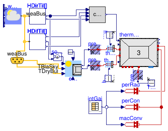
Illustrates the use of a thermal zone with three heat conduction elements
Information
This example shows the application of
Buildings.ThermalZones.ReducedOrder.RC.ThreeElements
in combination with
Buildings.ThermalZones.ReducedOrder.EquivalentAirTemperature.VDI6007WithWindow
and
Buildings.ThermalZones.ReducedOrder.SolarGain.CorrectionGDoublePane.
Solar radiation on tilted surface is calculated using models of
Buildings. The thermal zone is a simple room defined in Guideline
VDI 6007 Part 1 (VDI, 2012). All models, parameters and inputs
except sunblinds, separate handling of heat transfer through
windows, an extra wall element for ground floor (with additional
area) and solar radiation are similar to the ones defined for the
guideline's test room. For solar radiation, the example
relies on the standard weather file in Buildings.
The idea of the example is to show a typical application of
all sub-models and to use the example in unit tests. The results
are reasonable, but not related to any real use case or
measurement data.
References
VDI. German Association of Engineers Guideline VDI 6007-1 March
2012. Calculation of transient thermal response of rooms and
buildings - modelling of rooms.
Extends from Modelica.Icons.Example (Icon for runnable examples).
Connectors
| Type | Name | Description |
|---|
| Bus | weaBus | Weather data bus |
Modelica definition
model SimpleRoomThreeElements
extends Modelica.Icons.Example;
BoundaryConditions.WeatherData.ReaderTMY3 weaDat(
calTSky=Buildings.BoundaryConditions.Types.SkyTemperatureCalculation.HorizontalRadiation,
computeWetBulbTemperature=false,
filNam=
Modelica.Utilities.Files.loadResource("modelica://Buildings/Resources/weatherdata/USA_CA_San.Francisco.Intl.AP.724940_TMY3.mos"))
;
BoundaryConditions.SolarIrradiation.DiffusePerez HDifTil[2](
each outSkyCon=true,
each outGroCon=true,
each til=1.5707963267949,
azi={3.1415926535898,4.7123889803847})
;
BoundaryConditions.SolarIrradiation.DirectTiltedSurface HDirTil[2](
each til=1.5707963267949,
azi={3.1415926535898,4.7123889803847})
;
SolarGain.CorrectionGDoublePane corGDouPan(n=2, UWin=2.1)
;
RC.ThreeElements thermalZoneThreeElements(
VAir=52.5,
hConExt=2.7,
hConWin=2.7,
gWin=1,
ratioWinConRad=0.09,
nExt=1,
RExt={0.00331421908725},
CExt={5259932.23},
hRad=5,
AInt=60.5,
hConInt=2.12,
nInt=1,
RInt={0.000668895639141},
CInt={12391363.86},
RWin=0.01642857143,
RExtRem=0.1265217391,
AFloor=11.5,
hConFloor=2.7,
nFloor=1,
RFloor={0.00331421908725},
RFloorRem=0.1265217391,
CFloor={5259932.23},
AWin={7,7},
ATransparent={7,7},
AExt={3.5,8},
nOrientations=2,
redeclare package Medium =
Modelica.Media.Air.SimpleAir,
extWallRC(thermCapExt(
each der_T(fixed=true))),
energyDynamics=Modelica.Fluid.Types.Dynamics.FixedInitial,
intWallRC(thermCapInt(
each der_T(fixed=true))),
floorRC(thermCapExt(
each der_T(fixed=true))),
T_start=295.15) ;
EquivalentAirTemperature.VDI6007WithWindow eqAirTemp(
n=2,
wfGro=0,
wfWall={0.3043478260869566,0.6956521739130435},
wfWin={0.5,0.5},
withLongwave=true,
aExt=0.7,
hConWallOut=20,
hRad=5,
hConWinOut=20,
TGro=285.15) ;
Modelica.Blocks.Math.Add solRad[2]
;
Buildings.HeatTransfer.Sources.PrescribedTemperature preTem
;
Buildings.HeatTransfer.Sources.PrescribedTemperature preTem1
;
Modelica.Thermal.HeatTransfer.Components.Convection theConWin
;
Modelica.Thermal.HeatTransfer.Components.Convection theConWall
;
Modelica.Thermal.HeatTransfer.Sources.PrescribedHeatFlow perRad
;
Modelica.Thermal.HeatTransfer.Sources.PrescribedHeatFlow perCon
;
Modelica.Blocks.Sources.CombiTimeTable intGai(
table=[0,0,0,0; 3600,0,0,0; 7200,0,0,0; 10800,0,0,0; 14400,0,0,0; 18000,0,0,
0; 21600,0,0,0; 25200,0,0,0; 25200,80,80,200; 28800,80,80,200; 32400,80,
80,200; 36000,80,80,200; 39600,80,80,200; 43200,80,80,200; 46800,80,80,200;
50400,80,80,200; 54000,80,80,200; 57600,80,80,200; 61200,80,80,200; 61200,
0,0,0; 64800,0,0,0; 72000,0,0,0; 75600,0,0,0; 79200,0,0,0; 82800,0,0,0;
86400,0,0,0],
columns={2,3,4},
extrapolation=Modelica.Blocks.Types.Extrapolation.Periodic) ;
Modelica.Blocks.Sources.Constant const[2](
each k=0)
;
BoundaryConditions.WeatherData.Bus weaBus ;
Modelica.Thermal.HeatTransfer.Sources.PrescribedHeatFlow macConv
;
Modelica.Blocks.Sources.Constant hConWall(k=25*11.5)
;
Modelica.Blocks.Sources.Constant hConWin(k=20*14)
;
Buildings.HeatTransfer.Sources.PrescribedTemperature preTemFloor
;
Modelica.Blocks.Sources.Constant TSoil(k=283.15)
;
equation
connect(eqAirTemp.TEqAirWin, preTem1.T);
connect(eqAirTemp.TEqAir, preTem.T);
connect(weaDat.weaBus, weaBus);
connect(weaBus.TDryBul, eqAirTemp.TDryBul);
connect(intGai.y[1], perRad.Q_flow);
connect(intGai.y[2], perCon.Q_flow);
connect(intGai.y[3], macConv.Q_flow);
connect(const.y, eqAirTemp.sunblind);
connect(HDifTil.HSkyDifTil, corGDouPan.HSkyDifTil);
connect(HDirTil.H, corGDouPan.HDirTil);
connect(HDirTil.H,solRad. u1);
connect(HDirTil.inc, corGDouPan.inc);
connect(HDifTil.H,solRad. u2);
connect(HDifTil.HGroDifTil, corGDouPan.HGroDifTil);
connect(solRad.y, eqAirTemp.HSol);
connect(weaDat.weaBus, HDifTil[1].weaBus);
connect(weaDat.weaBus, HDifTil[2].weaBus);
connect(weaDat.weaBus, HDirTil[1].weaBus);
connect(weaDat.weaBus, HDirTil[2].weaBus);
connect(perRad.port, thermalZoneThreeElements.intGainsRad);
connect(theConWin.solid, thermalZoneThreeElements.window);
connect(preTem1.port, theConWin.fluid);
connect(thermalZoneThreeElements.extWall, theConWall.solid);
connect(theConWall.fluid, preTem.port);
connect(hConWall.y, theConWall.Gc);
connect(hConWin.y, theConWin.Gc);
connect(weaBus.TBlaSky, eqAirTemp.TBlaSky);
connect(macConv.port, thermalZoneThreeElements.intGainsConv);
connect(perCon.port, thermalZoneThreeElements.intGainsConv);
connect(preTemFloor.port, thermalZoneThreeElements.floor);
connect(TSoil.y, preTemFloor.T);
connect(corGDouPan.solarRadWinTrans, thermalZoneThreeElements.solRad);
end SimpleRoomThreeElements;
Illustrates the use of a thermal zone with two heat conduction elements
Information
This example shows the application of
Buildings.ThermalZones.ReducedOrder.RC.TwoElements
in combination with
Buildings.ThermalZones.ReducedOrder.EquivalentAirTemperature.VDI6007WithWindow
and
Buildings.ThermalZones.ReducedOrder.SolarGain.CorrectionGDoublePane.
Solar radiation on tilted surface is calculated using models of
Buildings. The thermal zone is a simple room defined in Guideline
VDI 6007 Part 1 (VDI, 2012). All models, parameters and inputs
except sunblinds, separate handling of heat transfer through
windows and solar radiation are similar to the ones defined for
the guideline's test room. For solar radiation, the example
relies on the standard weather file in Buildings.
The idea of the example is to show a typical application of
all sub-models and to use the example in unit tests. The results
are reasonable, but not related to any real use case or
measurement data.
References
VDI. German Association of Engineers Guideline VDI
6007-1 March 2012. Calculation of transient thermal response of
rooms and buildings - modelling of rooms.
Extends from Modelica.Icons.Example (Icon for runnable examples).
Connectors
| Type | Name | Description |
|---|
| Bus | weaBus | Weather data bus |
Modelica definition
model SimpleRoomTwoElements
extends Modelica.Icons.Example;
BoundaryConditions.WeatherData.ReaderTMY3 weaDat(
calTSky=Buildings.BoundaryConditions.Types.SkyTemperatureCalculation.HorizontalRadiation,
computeWetBulbTemperature=false,
filNam=
Modelica.Utilities.Files.loadResource("modelica://Buildings/Resources/weatherdata/USA_CA_San.Francisco.Intl.AP.724940_TMY3.mos"))
;
BoundaryConditions.SolarIrradiation.DiffusePerez HDifTil[2](
each outSkyCon=true,
each outGroCon=true,
each til=1.5707963267949,
azi={3.1415926535898,4.7123889803847})
;
BoundaryConditions.SolarIrradiation.DirectTiltedSurface HDirTil[2](
each til(displayUnit="deg") = 1.5707963267949,
azi={3.1415926535898, 4.7123889803847})
;
SolarGain.CorrectionGDoublePane corGDouPan(n=2, UWin=2.1)
;
RC.TwoElements thermalZoneTwoElements(
VAir=52.5,
hConExt=2.7,
hConWin=2.7,
gWin=1,
ratioWinConRad=0.09,
nExt=1,
RExt={0.00331421908725},
CExt={5259932.23},
hRad=5,
AInt=60.5,
hConInt=2.12,
nInt=1,
RInt={0.000668895639141},
CInt={12391363.86},
RWin=0.01642857143,
RExtRem=0.1265217391,
nOrientations=2,
AWin={7,7},
ATransparent={7,7},
AExt={3.5,8},
redeclare package Medium =
Modelica.Media.Air.SimpleAir,
extWallRC(thermCapExt(
each der_T(fixed=true))),
energyDynamics=Modelica.Fluid.Types.Dynamics.FixedInitial,
T_start=295.15,
intWallRC(thermCapInt(
each der_T(fixed=true)))) ;
EquivalentAirTemperature.VDI6007WithWindow eqAirTemp(
n=2,
wfGro=0,
wfWall={0.3043478260869566,0.6956521739130435},
wfWin={0.5,0.5},
withLongwave=true,
aExt=0.7,
hConWallOut=20,
hRad=5,
hConWinOut=20,
TGro=285.15) ;
Modelica.Blocks.Math.Add solRad[2]
;
Buildings.HeatTransfer.Sources.PrescribedTemperature preTem
;
Buildings.HeatTransfer.Sources.PrescribedTemperature preTem1
;
Modelica.Thermal.HeatTransfer.Components.Convection theConWin
;
Modelica.Thermal.HeatTransfer.Components.Convection theConWall
;
Modelica.Thermal.HeatTransfer.Sources.PrescribedHeatFlow perRad
;
Modelica.Thermal.HeatTransfer.Sources.PrescribedHeatFlow perCon
;
Modelica.Blocks.Sources.CombiTimeTable intGai(
table=[0,0,0,0; 3600,0,0,0; 7200,0,0,0; 10800,0,0,0; 14400,0,0,0; 18000,0,0,
0; 21600,0,0,0; 25200,0,0,0; 25200,80,80,200; 28800,80,80,200; 32400,80,
80,200; 36000,80,80,200; 39600,80,80,200; 43200,80,80,200; 46800,80,80,200;
50400,80,80,200; 54000,80,80,200; 57600,80,80,200; 61200,80,80,200; 61200,
0,0,0; 64800,0,0,0; 72000,0,0,0; 75600,0,0,0; 79200,0,0,0; 82800,0,0,0;
86400,0,0,0],
columns={2,3,4},
extrapolation=Modelica.Blocks.Types.Extrapolation.Periodic) ;
Modelica.Blocks.Sources.Constant const[2](
each k=0)
;
BoundaryConditions.WeatherData.Bus weaBus ;
Modelica.Thermal.HeatTransfer.Sources.PrescribedHeatFlow macConv
;
Modelica.Blocks.Sources.Constant hConWall(k=25*11.5)
;
Modelica.Blocks.Sources.Constant hConWin(k=20*14)
;
equation
connect(eqAirTemp.TEqAirWin, preTem1.T);
connect(eqAirTemp.TEqAir, preTem.T);
connect(weaDat.weaBus, weaBus);
connect(weaBus.TDryBul, eqAirTemp.TDryBul);
connect(intGai.y[1], perRad.Q_flow);
connect(intGai.y[2], perCon.Q_flow);
connect(intGai.y[3], macConv.Q_flow);
connect(const.y, eqAirTemp.sunblind);
connect(HDifTil.HSkyDifTil, corGDouPan.HSkyDifTil);
connect(HDirTil.H, corGDouPan.HDirTil);
connect(HDirTil.H,solRad. u1);
connect(HDirTil.inc, corGDouPan.inc);
connect(HDifTil.H,solRad. u2);
connect(HDifTil.HGroDifTil, corGDouPan.HGroDifTil);
connect(solRad.y, eqAirTemp.HSol);
connect(weaDat.weaBus, HDifTil[1].weaBus);
connect(weaDat.weaBus, HDifTil[2].weaBus);
connect(weaDat.weaBus, HDirTil[1].weaBus);
connect(weaDat.weaBus, HDirTil[2].weaBus);
connect(perRad.port, thermalZoneTwoElements.intGainsRad);
connect(theConWin.solid, thermalZoneTwoElements.window);
connect(preTem1.port, theConWin.fluid);
connect(thermalZoneTwoElements.extWall, theConWall.solid);
connect(theConWall.fluid, preTem.port);
connect(hConWall.y, theConWall.Gc);
connect(hConWin.y, theConWin.Gc);
connect(weaBus.TBlaSky, eqAirTemp.TBlaSky);
connect(macConv.port, thermalZoneTwoElements.intGainsConv);
connect(perCon.port, thermalZoneTwoElements.intGainsConv);
connect(corGDouPan.solarRadWinTrans, thermalZoneTwoElements.solRad);
end SimpleRoomTwoElements;
Illustrates the use of non-constant ground temperature for equivalent air temperature calculation
Information
This example shows the application of
Buildings.ThermalZones.ReducedOrder.RC.TwoElements
in connection with equivalent air temperature calculation in
Buildings.ThermalZones.ReducedOrder.EquivalentAirTemperature.VDI6007WithWindow,
where the ground temperature is not a constant, but has a trapezoid source.
Apart from that, it is identical to
Buildings.ThermalZones.ReducedOrder.Examples.SimpleRoomTwoElements.
References
VDI. German Association of Engineers Guideline VDI 6007-1
March 2012. Calculation of transient thermal response of rooms
and buildings - modelling of rooms.
Extends from Modelica.Icons.Example (Icon for runnable examples), Buildings.ThermalZones.ReducedOrder.Examples.SimpleRoomTwoElements (Illustrates the use of a thermal zone with two heat conduction elements).
Connectors
| Type | Name | Description |
|---|
| Bus | weaBus | Weather data bus |
Modelica definition
model SimpleRoomTwoElementsNonConstantTGround
extends Modelica.Icons.Example;
extends Buildings.ThermalZones.ReducedOrder.Examples.SimpleRoomTwoElements(
eqAirTemp(
wfWall={0.15,0.35},
wfGro=0.5,
TGroundFromInput=true));
Modelica.Blocks.Sources.Trapezoid TGro(
amplitude(unit="K") = 10,
rising(displayUnit="d") = 7884000,
width(displayUnit="d") = 7884000,
falling(displayUnit="d") = 7884000,
period(displayUnit="d") = 31536000,
offset(
unit="K",
displayUnit="degC") = 280.15,
startTime(displayUnit="d") = 5184000)
;
equation
connect(TGro.y, eqAirTemp.TGro_in);
end SimpleRoomTwoElementsNonConstantTGround;
 Buildings.ThermalZones.ReducedOrder.Examples.SimpleRoomFourElements
 Buildings.ThermalZones.ReducedOrder.Examples.SimpleRoomFourElementsTraceSubstance
 Buildings.ThermalZones.ReducedOrder.Examples.SimpleRoomOneElement
 Buildings.ThermalZones.ReducedOrder.Examples.SimpleRoomThreeElements
 Buildings.ThermalZones.ReducedOrder.Examples.SimpleRoomTwoElements
 Buildings.ThermalZones.ReducedOrder.Examples.SimpleRoomTwoElementsNonConstantTGround
