Buildings.Fluid.FixedResistances.BuriedPipes
Package with models for buried pipes
Information
This package contains models for buried pipes, such as those found in district heating and cooling distribution networks.
Extends from Modelica.Icons.VariantsPackage (Icon for package containing variants).
Package Content
| Name | Description |
|---|---|
| Thermal coupling between buried pipes and ground | |
| Collection of models that illustrate model use and test models | |
| Collection of validation models | |
| Package with base classes for Buildings.Fluid.Geothermal.BuriedPipes |
 Buildings.Fluid.FixedResistances.BuriedPipes.GroundCoupling
Thermal coupling between buried pipes and ground

Information
This model simulates the heat transfer between multiple buried pipes and the ground, using climate and soil information and the geometry of the pipes network.
The model can take any number of pipes, and can be discretized axially in any number of segments. Currently, the model only allows for pipes that run co-axially and parallel to the ground, and the axial segmentation must be the same for each pipe.
The heat transfer solution is based upon the potential flow theory and obtained by the use of "mirror-image" technique suggested by Eckert (1959). This technique is extended to a network with multiple pipes by Kusuda (1981) in the equation:

where:
L = pipe length [m]
ks = soil thermal conductivity [W/(m.K)]
Pij = geometric factor (see
Buildings.Fluid.FixedResistances.BuriedPipes.BaseClasses.groundCouplingFactors
for more information)
Qi = net heat transfer from pipe i [W]
Ti = temperature at the exterior surface of pipe i [degC]
Tg = undisturbed ground temperature at the depth of the
network. [degC]
This model relies on the following assumptions.
- Heat transfer is in steady state.
- The heat transfer is radial (no axial diffusion).
- The exterior surfaces for each pipe segment are isothermic planes.
- The ground surface is an isothermic plane.
- The soil conductivity is homogeneous and isotropic.
References
Eckert, E. R. G. (1959). Heat and Mass Transfer. McGraw-Hill Book Company.
Kusuda, T. (1981). Heat transfer analysis of underground heat
and chilled-water distribution systems. National Bureau of Standards.
Parameters
| Type | Name | Default | Description |
|---|---|---|---|
| Integer | nPip | Number of buried pipes | |
| Integer | nSeg | 1 | Number of axial segments |
| Generic | soiDat | redeclare parameter Building... | Soil thermal properties |
| Generic | cliCon | redeclare parameter Building... | Surface temperature climatic conditions |
| Length | len[nSeg] | Pipes length [m] | |
| Length | dep[nPip] | Pipes buried depth [m] | |
| Length | pos[nPip] | Pipes horizontal coordinate (to an arbitrary reference point) [m] | |
| Length | rad[nPip] | Pipes external radius [m] |
Connectors
| Type | Name | Description |
|---|---|---|
| HeatPort_a | ports[nPip, nSeg] | Buried pipes heatports |
Modelica definition
 Buildings.Fluid.FixedResistances.BuriedPipes.PipeGroundCoupling

Information
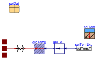
This model considers the conduction heat transfer between the buried pipe wall and the undisturbed ground temperature by adding a dynamic ground layer. The dynamic ground layer is modeled using the radial heat conduction model through a hollow cylinder Buildings.HeatTransfer.Conduction.SingleLayerCylinder. The undisturbed ground temperature is calculated by the model Buildings.BoundaryConditions.GroundTemperature.UndisturbedSoilTemperature. This model can consider an axial discretization of the pipe. A figure highlighting the main variables and parameters is shown below:

References
Ettore Zanetti, David Blum, Michael Wetter (2023) Control development and sizing analysis for a 5th generation district heating and cooling network using Modelica, In Proceedings of the 15th International Modelica Conference. Aachen, Germany, Oct 9-11, 2023.
Parameters
| Type | Name | Default | Description |
|---|---|---|---|
| Height | lPip | 100 | Pipe length [m] |
| Radius | rPip | 0.5 | Pipe external radius [m] |
| Radius | thiGroLay | 1.0 | Dynamic ground layer thickness [m] |
| Integer | nSeg | 10 | Number of pipe discretization segments axial direction |
| Integer | nSta | 1 | Number of state variables for dynamic ground layer |
| Length | dep | 10 | Depth of buried pipe to calculate ground temperature [m] |
| Zurich | cliCon | redeclare parameter Building... | Surface temperature climatic conditions |
| Generic | soiDat | soiDat(k=1.58, c=1150, d=1600) | Soil thermal properties |
| Initialization | |||
| Temperature | TpipSta | 280.15 | Initial temperature for the pipe, used if steadyStateInitial = false [K] |
| Temperature | TGrouBouSta | 283.15 | Initial temperature at ground final layer, used if steadyStateInitial = false [K] |
| Boolean | steadyStateInitial | false | true initializes dT(0)/dt=0, false initializes T(0) at fixed temperature using TpipSta and TGrouBouSta |
Connectors
| Type | Name | Description |
|---|---|---|
| HeatPorts_a | heatPorts[nSeg] | Multiple heat ports that connect to outside of pipe wall |
