Buildings.Examples.Tutorial.SimpleHouse
Package with example for how to build a simple building envelope with a radiator heating system and ventilation system
Information
This package contains examples with step-by-step instructions for how to build a system model
for a simple house with a heating system, ventilation, and weather boundary conditions.
It serves as a demonstration case of how the Buildings library can be used.
The goal of this exercise is to become familiar with Modelica and the Buildings library. Since the Buildings library components are typically used by combining several components graphically, the use of equations falls outside of the scope of this exercise.
For this exercise you will create a model of a simple house, consisting of a heating system, one building zone, and a ventilation model. The exercise starts from a template file that should not produce any errors. This file will be extended in several steps, adding complexity. In between each step the user should be able to simulate the model, i.e., no errors should be produced and simulation results may be compared.
The model has been created in the following stages:
-
Buildings.Examples.Tutorial.SimpleHouse.SimpleHouse0
contains a weather data reader which connects the data of the dry bulb temperature
to a
PrescribedTemperaturecomponent and serves as a starting model to implement the entireSimpleHousemodel. - Buildings.Examples.Tutorial.SimpleHouse.SimpleHouse1 implements the building wall by adding a thermal capacity.
- Buildings.Examples.Tutorial.SimpleHouse.SimpleHouse2 adds a window to the building wall. It is assumed that the total injected heat through the window equals the window surface area multiplied by the direct horizontal solar irradiance.
- Buildings.Examples.Tutorial.SimpleHouse.SimpleHouse3 adds an air model which represents the room in the building.
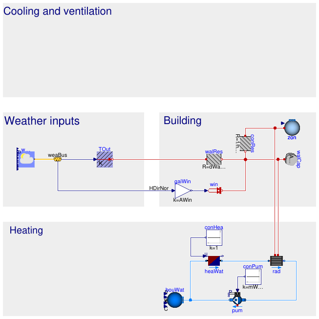
- Buildings.Examples.Tutorial.SimpleHouse.SimpleHouse4 adds heating circuit consisting of a boiler, a radiator, and an on/off circulation pump with a constant mass flow rate. No controller is implemented yet, i.e. the pump and heater are always on.
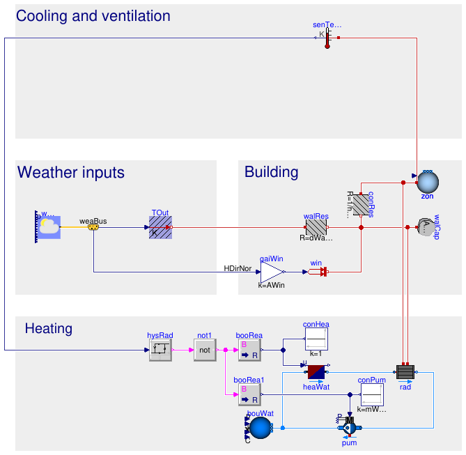
- Buildings.Examples.Tutorial.SimpleHouse.SimpleHouse5 adds a hysteresis controller for the heating circuit that uses the room temperature as an input.
- Buildings.Examples.Tutorial.SimpleHouse.SimpleHouse6 adds a ventilation system consisting of a fan, a damper, a heat recovery unit, and a hysteresis controller, that allows to perform free cooling using outside air.
For each stage, firstly the model part is qualitatively explained. Next, the names of the required Modelica models (from the Modelica Standard Library and/or Buildings library) are listed. Finally, we provide high-level instructions of how to set up the model. If these instructions are not clear immediately, have a look at the model documentation and at the type of connectors the model has, try out some things, make an educated guess, etc. Finally, we provide reference results that allow you to check if your implementation is correct. Depending on the parameter values that you choose, results may differ.
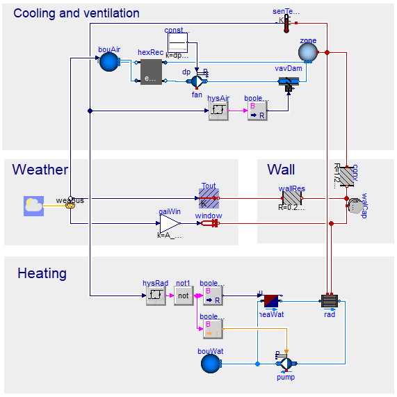
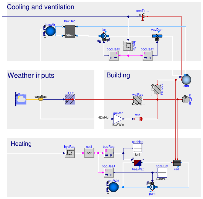
The graphical representation of the final model is given below.
Extends from Modelica.Icons.ExamplesPackage (Icon for packages containing runnable examples).
Package Content
| Name | Description |
|---|---|
| Start file for simple house example | |
| Building wall model | |
| Building window model | |
| Air model | |
| Heating model | |
| Heating controller model | |
| Free cooling model |
 Buildings.Examples.Tutorial.SimpleHouse.SimpleHouse0
Start file for simple house example
Information
This model is used as the starting point for the
Buildings.Examples.Tutorial.SimpleHouse
tutorial.
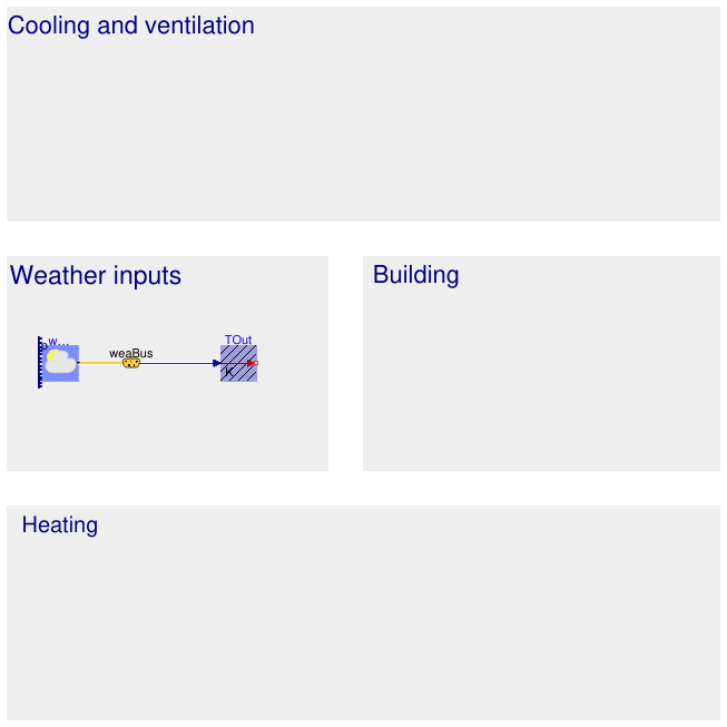
It contains a weather data reader and a PrescribedTemperature component
that allows the user to connect thermal components to the dry bulb temperature.
It was based on from the Modelica crash course organised by KU Leuven
(https://github.com/open-ideas/__CrashCourse__).
Extends from Modelica.Icons.Example (Icon for runnable examples).
Parameters
| Type | Name | Default | Description |
|---|---|---|---|
| Area | AWall | 100 | Wall area [m2] |
| Length | dWall | 0.25 | Wall thickness [m] |
| ThermalConductivity | kWall | 0.04 | Wall thermal conductivity [W/(m.K)] |
| Density | rhoWall | 2000 | Wall density [kg/m3] |
| SpecificHeatCapacity | cpWall | 1000 | Wall specific heat capacity [J/(kg.K)] |
Connectors
| Type | Name | Description |
|---|---|---|
| Bus | weaBus | Weather data bus |
Modelica definition
Buildings.Examples.Tutorial.SimpleHouse.SimpleHouse1
Building wall model
Information
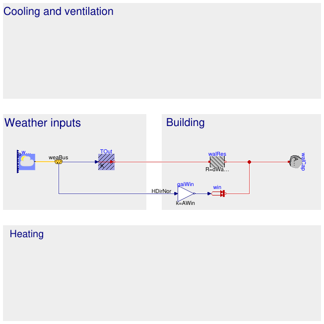
A very simple building envelope model will be constructed manually using thermal resistors and heat capacitors. The house consists of a wall represented by a single heat capacitor and a thermal resistor. The boundary temperature are already included in Buildings.Examples.Tutorial.SimpleHouse.SimpleHouse0. The wall has a surface area of Awall=100 m2, a thickness of dwall=25 cm, a thermal conductivity of kwall=0.04 W/(m K), a density of ρwall=2000 kg/m3, and a specific heat capacity of cp,wall= 1000 J/(kg K)
These parameters are already declared in the equation section of Buildings.Examples.Tutorial.SimpleHouse.SimpleHouse0. You can use this way of declaring parameters in the remainder of this exercise, but this is not required.
The conductive thermal resistance value of a wall may be computed as R=d/(A*k). The heat capacity value of a wall may be computed as C=A*d*cp*ρ
Required models
- Modelica.Thermal.HeatTransfer.Components.HeatCapacitor
- Modelica.Thermal.HeatTransfer.Components.ThermalResistor
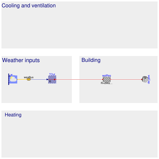
Connection instructions
Connect one side of the thermal resistor to the output of PrescribedTemperature
and the other side of the thermal resistor to the heat capacitor.
Reference result
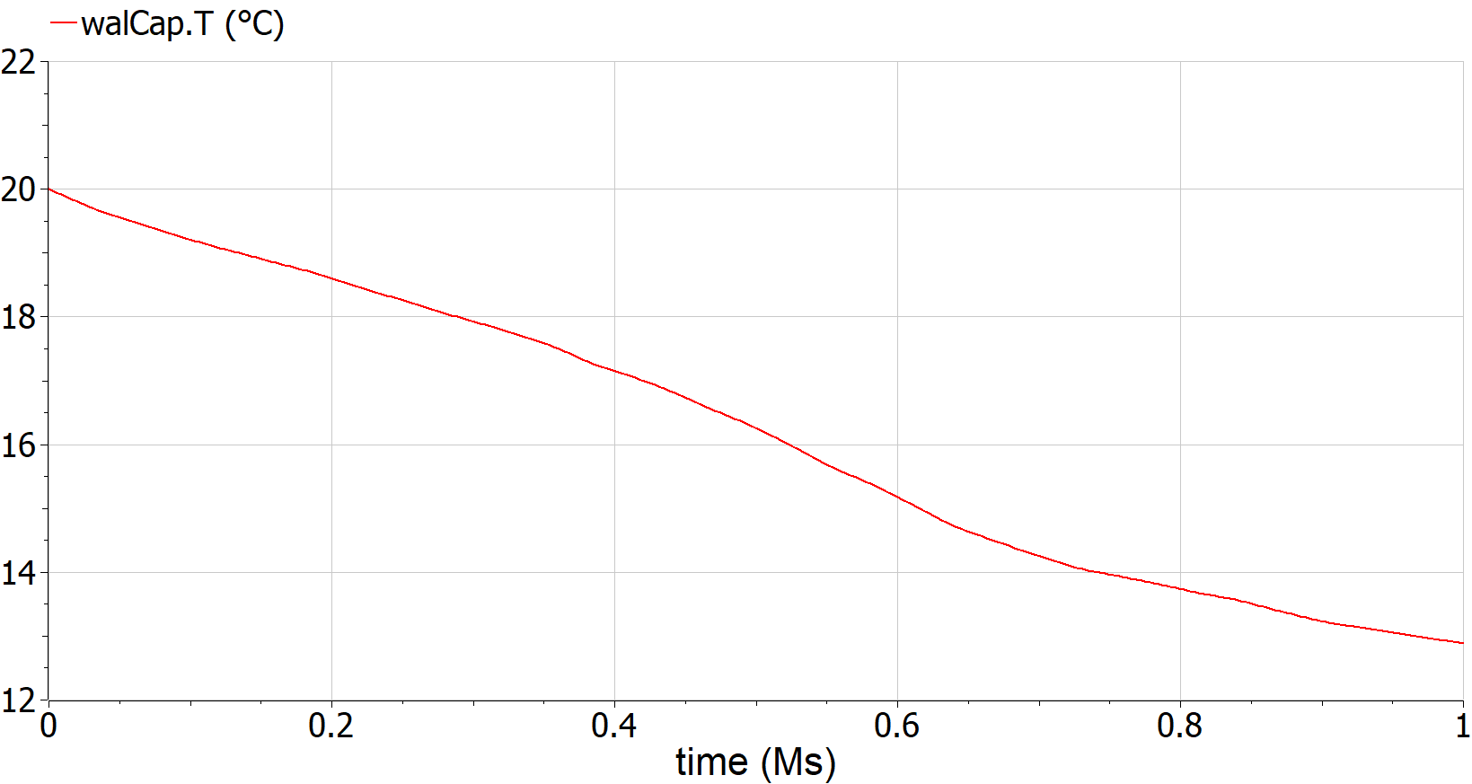
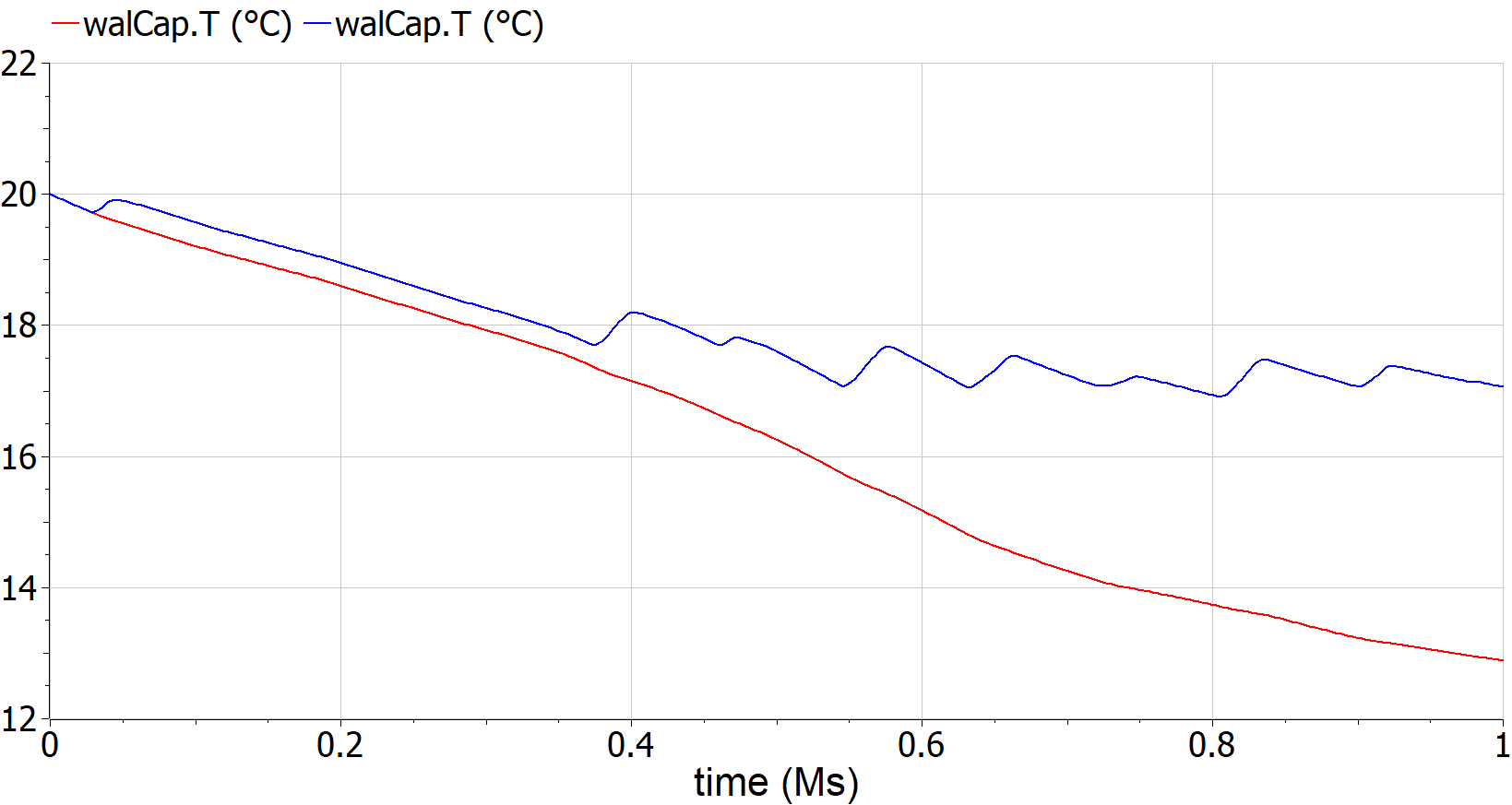
If you correctly added the model of the heat capacitor, connected it to the resistor and added the parameter values for C, then you should be able to simulate the model. To do this, press the Simulation Setup and set the model Stop time to 1e6 seconds. You can now simulate the model by pressing the Simulate button.
You can plot individual variables values by clicking on their name in the variable browser on the left. Now plot the wall capacitor temperature value T. It should look like the figure below (1 Ms is around 12 days).
Extends from SimpleHouse0 (Start file for simple house example).
Parameters
| Type | Name | Default | Description |
|---|---|---|---|
| Area | AWall | 100 | Wall area [m2] |
| Length | dWall | 0.25 | Wall thickness [m] |
| ThermalConductivity | kWall | 0.04 | Wall thermal conductivity [W/(m.K)] |
| Density | rhoWall | 2000 | Wall density [kg/m3] |
| SpecificHeatCapacity | cpWall | 1000 | Wall specific heat capacity [J/(kg.K)] |
Connectors
| Type | Name | Description |
|---|---|---|
| Bus | weaBus | Weather data bus |
Modelica definition
Buildings.Examples.Tutorial.SimpleHouse.SimpleHouse2
Building window model
Information
The window has a surface area of 2 m2. In this simple model we will therefore assume that two times the outdoor solar irradiance is injected as heat onto the inside of the wall.
Required models
Connection instructions
To be able to use the value of the outdoor solar irradiance
you will need to access the weather data reader.
To do this, make a connection to the weaBus.
In the dialog box, select HDirNor,
which is the direct solar irradiance on a surface of 1 m2,
perpendicular to the sun rays.
Set the gain factor k to 2,
in order to get the solar irradiance through the window of 2 m2.
Make a connection with the PrescribedHeatFlow as well.
This block makes the connection between the heat flow from the gain, represented as a real value,
and a heat port that is compatible with the connectors of the thermal capacitance and resistance.
Reference result
The result with and without the window model is plotted in the figure below.
Extends from SimpleHouse1 (Building wall model).
Parameters
| Type | Name | Default | Description |
|---|---|---|---|
| Area | AWall | 100 | Wall area [m2] |
| Length | dWall | 0.25 | Wall thickness [m] |
| ThermalConductivity | kWall | 0.04 | Wall thermal conductivity [W/(m.K)] |
| Density | rhoWall | 2000 | Wall density [kg/m3] |
| SpecificHeatCapacity | cpWall | 1000 | Wall specific heat capacity [J/(kg.K)] |
| Area | AWin | 2 | Window area [m2] |
Connectors
| Type | Name | Description |
|---|---|---|
| Bus | weaBus | Weather data bus |
Modelica definition
Buildings.Examples.Tutorial.SimpleHouse.SimpleHouse3
Air model
Information
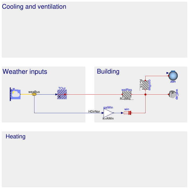
To increase the model detail we now add an air model assuming the zone is 8m x 8m x 3m in size. The air will exchange heat with the wall. This may be modelled using a thermal resistance representing the convective heat resistance which is equal to Rconv=1/(h*A), where A is the heat exchange surface area and h=2 W/(m2*K) is the convective heat transfer coefficient.
Required models
Connection instructions
The MixingVolume Medium parameter contains information about
the type of fluid and its properties that should be modelled by the MixingVolume.
Set its value to MediumAir, which is declared in the template,
by typing redeclare package Medium = MediumAir.
For the nominal mass flow rate you may assume a value of 1 kg/m3 for now.
You will have to change this value once you add a ventilation system to the model (see
Buildings.Examples.Tutorial.SimpleHouse.SimpleHouse6).
Finally, set the energyDynamics of the MixingVolume,
which can be found in the Dynamics tab of the model parameter window, to FixedInitial.
Make a connection with the PrescribedHeatFlow as well.
This block makes the connection between the heat flow from the gain, represented as a real value,
and a heat port that is compatible with the connectors of the thermal capacitance and resistance.
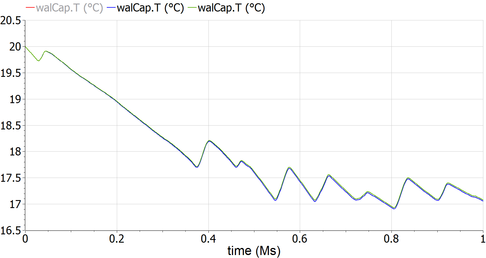
Reference result
The result with and without the air model is plotted in the figure below.
Extends from SimpleHouse2 (Building window model).
Parameters
| Type | Name | Default | Description |
|---|---|---|---|
| Area | AWall | 100 | Wall area [m2] |
| Length | dWall | 0.25 | Wall thickness [m] |
| ThermalConductivity | kWall | 0.04 | Wall thermal conductivity [W/(m.K)] |
| Density | rhoWall | 2000 | Wall density [kg/m3] |
| SpecificHeatCapacity | cpWall | 1000 | Wall specific heat capacity [J/(kg.K)] |
| Area | AWin | 2 | Window area [m2] |
| Volume | VZone | 8*8*3 | Zone volume [m3] |
| MassFlowRate | mAir_flow_nominal | 1 | Nominal mass flow rate for air loop [kg/s] |
| CoefficientOfHeatTransfer | hWall | 2 | Convective heat transfer coefficient at the wall [W/(m2.K)] |
Connectors
| Type | Name | Description |
|---|---|---|
| Bus | weaBus | Weather data bus |
Modelica definition
Buildings.Examples.Tutorial.SimpleHouse.SimpleHouse4
Heating model
Information
The wall temperature (and therefore the room temperature) is quite low. In this step a heating system is added to resolve this. It consists of a radiator, a pump and a heater. The radiator has a nominal power of 3 kW for an inlet and outlet temperature of the radiator of 60°C and 40°C, and a room air and radiative temperature of 20°C. The pump has a (nominal) mass flow rate of 0.1 kg/s. Since the heating system uses water as a heat carrier fluid, the media for the models in the heating circuit should be set to MediumWater.
Required models
- Buildings.Fluid.HeatExchangers.HeaterCooler_u
- Buildings.Fluid.HeatExchangers.Radiators.RadiatorEN442_2
- Buildings.Fluid.Movers.Preconfigured.FlowControlled_m_flow
- Buildings.Fluid.Sources.Boundary_pT
- Modelica.Blocks.Sources.Constant
Connection instructions
The radiator contains one port for convective heat transfer and one for radiative heat transfer.
Connect both in a reasonable way. Since the heating system uses water as a heat carrier fluid,
the media for the models should be set to MediumWater.
The Boundary_pT model needs to be used to set an absolute pressure somewhere in the system.
Otherwise the absolute pressure in the system is undefined.
Pressure difference modelling may be disregarded in the heating circuit
since the chosen pump sets a fixed mass flow rate regardless of the pressure drop.
Set the heater input to 1, meaning that it will produce 1 times its nominal power.
Implementation
The pump and the heater need a control input, which we set here to a constant
of 1.
However, in the next version of this model, we want to connect an actual controller to these models.
We can therefore introduce a Boolean constant (or a Boolean parameter
would also work), and use this to conditionally remove the Modelica block
that outputs the control signal. When Modelica removes such a block, then all
connections to it will also be removed.
Reference result
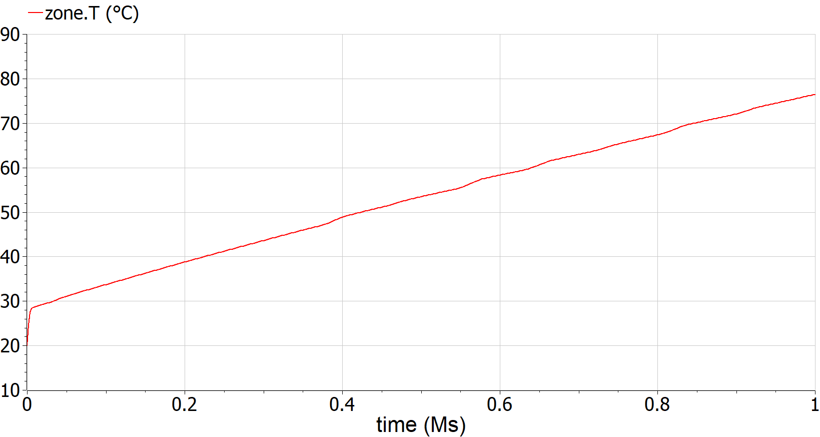
The result of the air temperature is plotted in the figure below. The temperature rises very steeply since the wall is relatively well insulated (k=0.04 W/(m*K)) and the heater is not disabled when it becomes too warm.
Extends from SimpleHouse3 (Air model).
Parameters
| Type | Name | Default | Description |
|---|---|---|---|
| Area | AWall | 100 | Wall area [m2] |
| Length | dWall | 0.25 | Wall thickness [m] |
| ThermalConductivity | kWall | 0.04 | Wall thermal conductivity [W/(m.K)] |
| Density | rhoWall | 2000 | Wall density [kg/m3] |
| SpecificHeatCapacity | cpWall | 1000 | Wall specific heat capacity [J/(kg.K)] |
| Area | AWin | 2 | Window area [m2] |
| Volume | VZone | 8*8*3 | Zone volume [m3] |
| MassFlowRate | mAir_flow_nominal | 1 | Nominal mass flow rate for air loop [kg/s] |
| CoefficientOfHeatTransfer | hWall | 2 | Convective heat transfer coefficient at the wall [W/(m2.K)] |
| HeatFlowRate | QHea_flow_nominal | 3000 | Nominal capacity of heating system [W] |
| MassFlowRate | mWat_flow_nominal | 0.1 | Nominal mass flow rate for water loop [kg/s] |
Connectors
| Type | Name | Description |
|---|---|---|
| Bus | weaBus | Weather data bus |
Modelica definition
Buildings.Examples.Tutorial.SimpleHouse.SimpleHouse5
Heating controller model
Information
Since the zone becomes too warm, a controller is required that disables the heater when a setpoint is reached. We will implement a hysteresis controller with a setpoint of 295.15 +/- 1K (21-23°C). A temperature sensor will measure the zone air temperature.
Required models
- Modelica.Blocks.Logical.Hysteresis
- Modelica.Blocks.Logical.Not
- Modelica.Blocks.Math.BooleanToReal
- Modelica.Thermal.HeatTransfer.Sensors.TemperatureSensor
Connection instructions
The heater modulation level should be set to 1 when the heater is on and to 0 otherwise. Furthermore, the pump should only circulate water when the heater is on.
Reference result
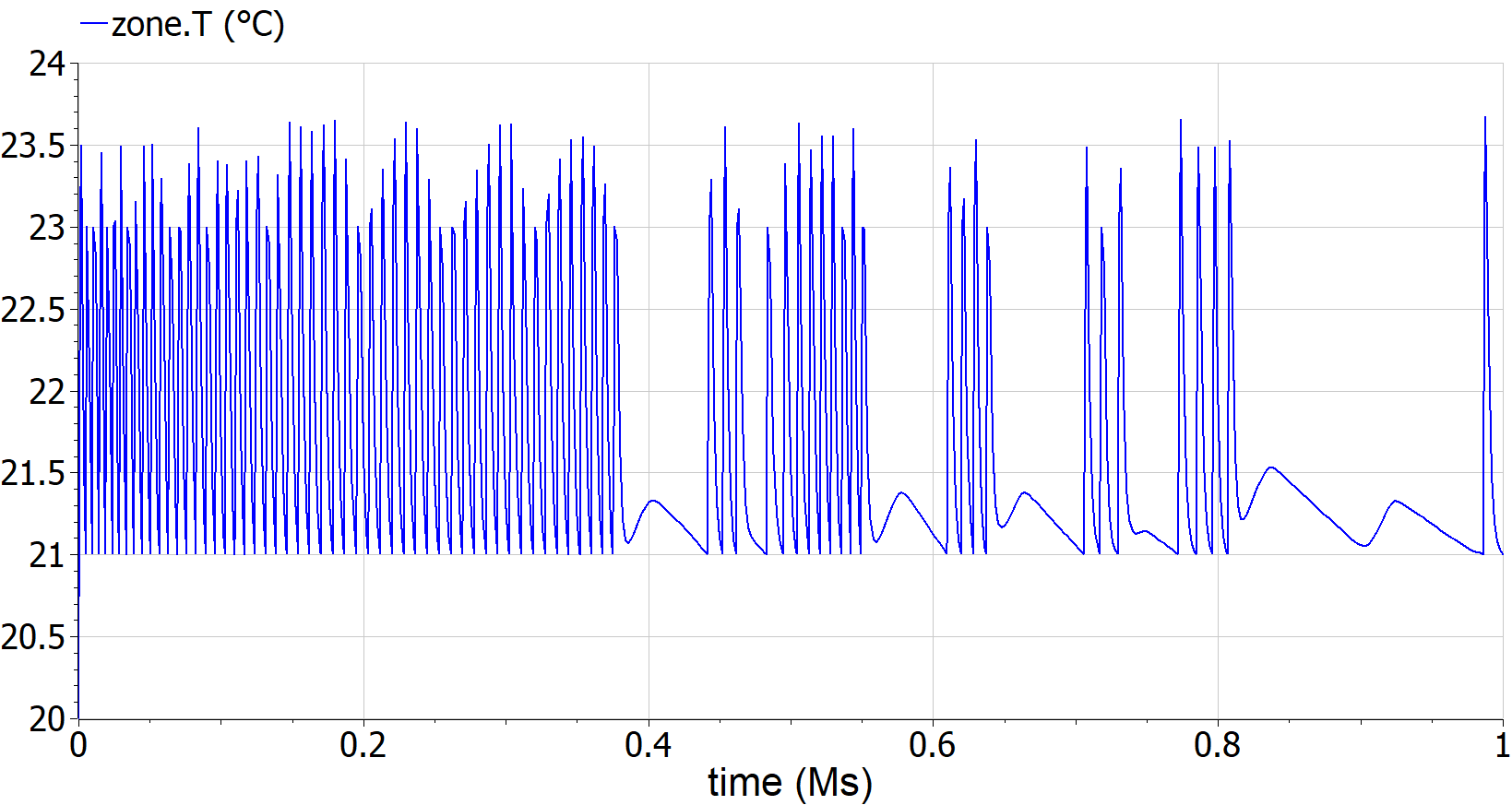
The figure below shows the air temperature after the controller is added.
Extends from SimpleHouse4 (Heating model).
Parameters
| Type | Name | Default | Description |
|---|---|---|---|
| Area | AWall | 100 | Wall area [m2] |
| Length | dWall | 0.25 | Wall thickness [m] |
| ThermalConductivity | kWall | 0.04 | Wall thermal conductivity [W/(m.K)] |
| Density | rhoWall | 2000 | Wall density [kg/m3] |
| SpecificHeatCapacity | cpWall | 1000 | Wall specific heat capacity [J/(kg.K)] |
| Area | AWin | 2 | Window area [m2] |
| Volume | VZone | 8*8*3 | Zone volume [m3] |
| MassFlowRate | mAir_flow_nominal | 1 | Nominal mass flow rate for air loop [kg/s] |
| CoefficientOfHeatTransfer | hWall | 2 | Convective heat transfer coefficient at the wall [W/(m2.K)] |
| HeatFlowRate | QHea_flow_nominal | 3000 | Nominal capacity of heating system [W] |
| MassFlowRate | mWat_flow_nominal | 0.1 | Nominal mass flow rate for water loop [kg/s] |
Connectors
| Type | Name | Description |
|---|---|---|
| Bus | weaBus | Weather data bus |
Modelica definition
Buildings.Examples.Tutorial.SimpleHouse.SimpleHouse6
Free cooling model
Information
For this last exercise, we first increase the window size from 2 m2 to 6 m2.
We will add a ventilation model that allows to perform free cooling using outside air when solar irradiation heats up the room too much. The system consists of a fan, a damper, a controller with an air temperature setpoint between 23°C and 25°C, and a heat recovery unit with a constant effectiveness of 85%. The damper and fan have a nominal pressure drop/raise of 200 Pa. The heat recovery unit has a nominal pressure drop of 10 Pa at both sides. The nominal mass flow rate of the ventilation system is 0.1 kg/s.
Required models
- Buildings.Fluid.Actuators.Dampers.Exponential
- Buildings.Fluid.HeatExchangers.ConstantEffectiveness
- Buildings.Fluid.Movers.Preconfigured.FlowControlled_dp
- Buildings.Fluid.Sources.Boundary_pT
- Modelica.Blocks.Logical.Hysteresis
- Modelica.Blocks.Math.BooleanToReal
Connection instructions
Connect the components such that they exchange mass (and therefore also energy)
with the MixingVolume representing the zone air.
Add a boundary_pT to draw air from the environment.
Enable its temperature input and connect it to the TDryBul variable in the weather data reader.
Also reconsider the nominal mass flow rate parameter value in the MixingVolume
given the flow rate information of the ventilation system.
Finally, make sure that the fan is only active when the damper is open.
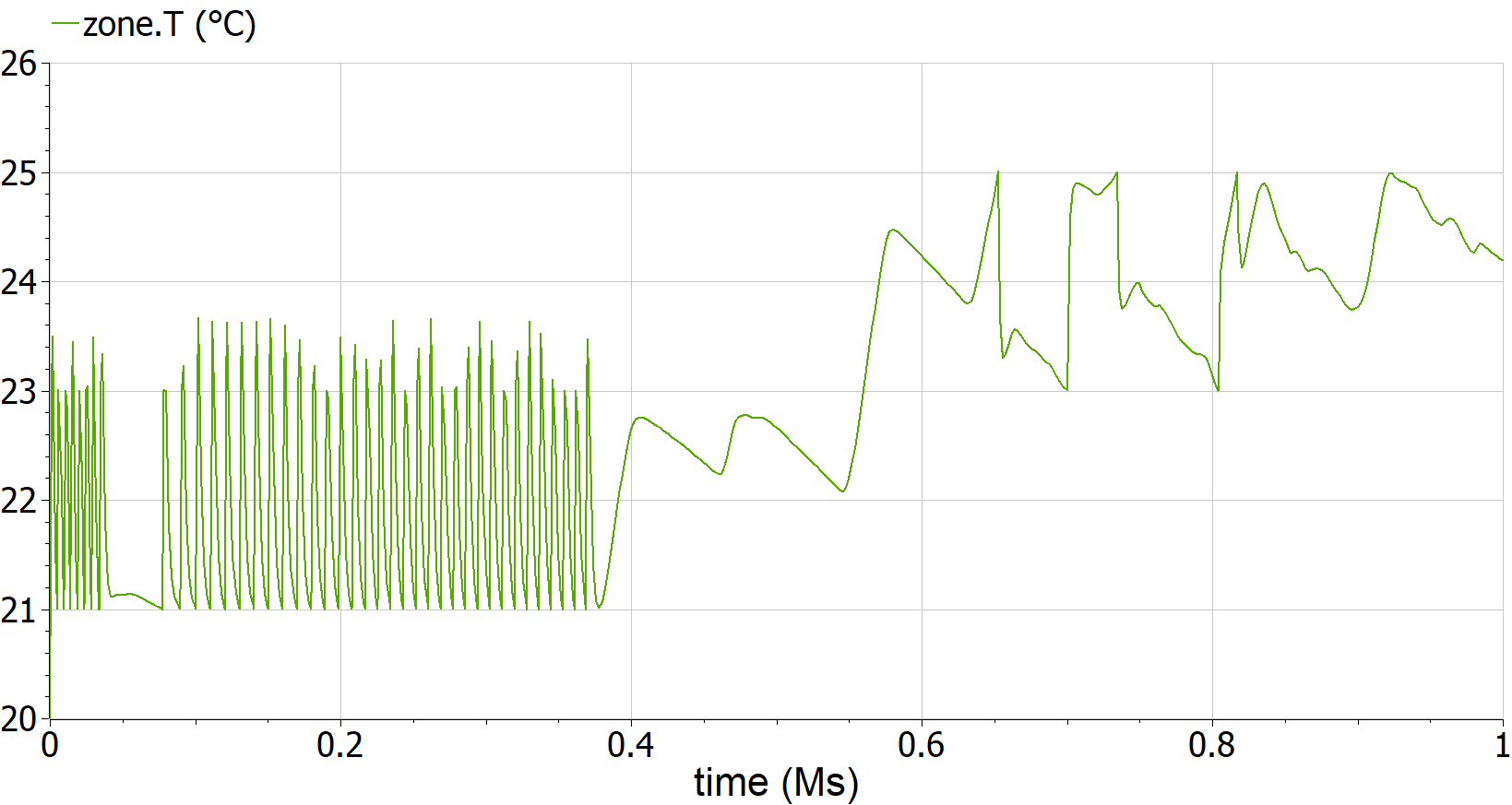
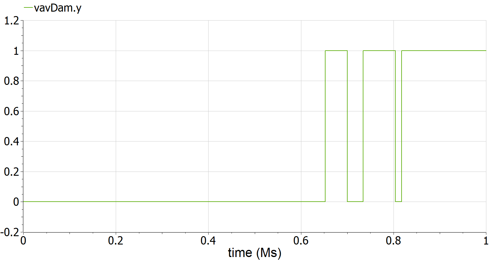
Reference result
The figures below show the results.
Extends from SimpleHouse5 (Heating controller model).
Parameters
| Type | Name | Default | Description |
|---|---|---|---|
| Area | AWall | 100 | Wall area [m2] |
| Length | dWall | 0.25 | Wall thickness [m] |
| ThermalConductivity | kWall | 0.04 | Wall thermal conductivity [W/(m.K)] |
| Density | rhoWall | 2000 | Wall density [kg/m3] |
| SpecificHeatCapacity | cpWall | 1000 | Wall specific heat capacity [J/(kg.K)] |
| Area | AWin | 6 | Window area [m2] |
| Volume | VZone | 8*8*3 | Zone volume [m3] |
| MassFlowRate | mAir_flow_nominal | 0.1 | Nominal mass flow rate for air loop [kg/s] |
| CoefficientOfHeatTransfer | hWall | 2 | Convective heat transfer coefficient at the wall [W/(m2.K)] |
| HeatFlowRate | QHea_flow_nominal | 3000 | Nominal capacity of heating system [W] |
| MassFlowRate | mWat_flow_nominal | 0.1 | Nominal mass flow rate for water loop [kg/s] |
| PressureDifference | dpAir_nominal | 200 | Pressure drop at nominal mass flow rate for air loop [Pa] |
Connectors
| Type | Name | Description |
|---|---|---|
| Bus | weaBus | Weather data bus |