Buildings.Controls.OBC.CDL.Logical
Package with logical blocks
Information
Package with blocks for elementary mathematical functions for boolean variables.
Package Content
| Name | Description |
|---|---|
| Logical 'and': y = u1 and u2 | |
| Output y is true, if the input u has a rising or falling edge (y = change(u)) | |
| Output y is true, if the input u has a rising edge (y = edge(u)) | |
| Output y is true, if the input u has a falling edge (y = edge(not u)) | |
| Maintains a true signal until change condition | |
| Logical MultiAnd, y = u[1] and u[2] and u[3] and ... | |
| Logical MultiOr, y = u[1] or u[2] or u[3] or ... | |
| Logical 'nand': y = not (u1 and u2) | |
| Logical 'nor': y = not (u1 or u2) | |
| Logical not | |
| On-off controller | |
| Logical 'or': y = u1 or u2 | |
| Logical 'or': y = u1 or u2 or u3 | |
| Breaks algebraic loops by an infinitesimal small time delay (y = pre(u): event iteration continues until u = pre(u)) | |
| Verify two boolean inputs | |
| Switch between two boolean signals | |
| Timer measuring the time from the time instant where the Boolean input became true | |
| Accumulating timer that can be reset | |
| Toggles output value whenever its input turns true | |
| Triggered trapezoid generator | |
| Delay a rising edge of the input, but do not delay a falling edge. | |
| Block that holds an output signal for at least a specified duration | |
| Block that holds a true signal for at least a requested duration | |
| Generate boolean pulse with the width specified by input | |
| Logical 'xor': y = u1 xor u2 | |
| Trigger zero crossing of input u | |
| Package with blocks that generate source signals | |
| Collection of models that validate the logical blocks of the CDL |
 Buildings.Controls.OBC.CDL.Logical.And
Logical 'and': y = u1 and u2
Information
Block that outputs true if all inputs are true.
Otherwise the output is false.
Connectors
| Type | Name | Description |
|---|---|---|
| input BooleanInput | u1 | Connector of first Boolean input signal |
| input BooleanInput | u2 | Connector of second Boolean input signal |
| output BooleanOutput | y | Connector of Boolean output signal |
Modelica definition
 Buildings.Controls.OBC.CDL.Logical.Change
Output y is true, if the input u has a rising or falling edge (y = change(u))

Information
Block that outputs true if the Boolean input has either a rising edge
from false to true or a falling edge from
true to false.
Otherwise the output is false.
Parameters
| Type | Name | Default | Description |
|---|---|---|---|
| Boolean | pre_u_start | false | Start value of pre(u) at initial time |
Connectors
| Type | Name | Description |
|---|---|---|
| input BooleanInput | u | Connector of Boolean input signal |
| output BooleanOutput | y | Connector of Boolean output signal |
Modelica definition
Buildings.Controls.OBC.CDL.Logical.Edge
Output y is true, if the input u has a rising edge (y = edge(u))
Information
Block that outputs true if the Boolean input has a rising edge
from false to true.
Otherwise the output is false.
Parameters
| Type | Name | Default | Description |
|---|---|---|---|
| Boolean | pre_u_start | false | Start value of pre(u) at initial time |
Connectors
| Type | Name | Description |
|---|---|---|
| input BooleanInput | u | Connector of Boolean input signal |
| output BooleanOutput | y | Connector of Boolean output signal |
Modelica definition
Buildings.Controls.OBC.CDL.Logical.FallingEdge
Output y is true, if the input u has a falling edge (y = edge(not u))
Information
Block that outputs true if the Boolean input has a falling edge
from true to false.
Otherwise the output is false.
Parameters
| Type | Name | Default | Description |
|---|---|---|---|
| Boolean | pre_u_start | false | Start value of pre(u) at initial time |
Connectors
| Type | Name | Description |
|---|---|---|
| input BooleanInput | u | Connector of Boolean input signal |
| output BooleanOutput | y | Connector of Boolean output signal |
Modelica definition
 Buildings.Controls.OBC.CDL.Logical.Latch
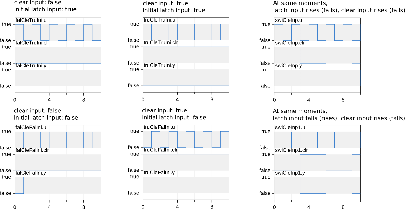
Maintains a true signal until change condition
Information
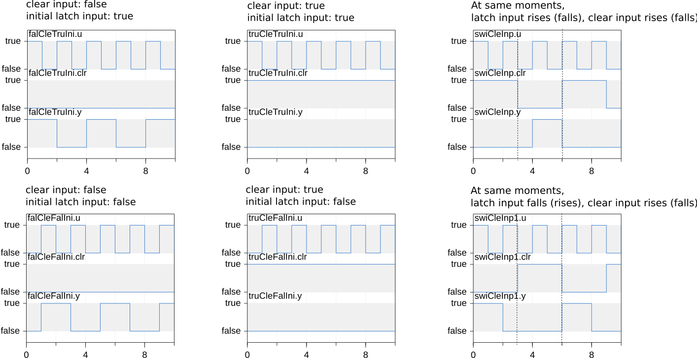
Block that generates a true output when the latch input u
rises from false to true, provided that the clear input
clr is false or also became at the same time false.
The output remains true until the clear input clr rises
from false to true.
If the clear input clr is true, the output y
switches to false (if it was true) and it remains false,
regardless of the value of the latch input u.
At initial time, if clr = false, then the output will be
y = u. Otherwise it will be y=false
(because the clear input clr is true).
Connectors
| Type | Name | Description |
|---|---|---|
| input BooleanInput | u | Latch input |
| input BooleanInput | clr | Clear input |
| output BooleanOutput | y | Output signal |
Modelica definition
 Buildings.Controls.OBC.CDL.Logical.MultiAnd
Logical MultiAnd, y = u[1] and u[2] and u[3] and ...

Information
Block that outputs y = true if and only if
all elements of the input vector u are true.
If no connection to the input connector u is present,
the output is y=false.
See Buildings.Controls.OBC.CDL.Logical.Validation.MultiAnd for an example.
Connectors
| Type | Name | Description |
|---|---|---|
| input BooleanInput | u[nin] | Connector of Boolean input signals |
| output BooleanOutput | y | Connector of Boolean output signal |
Modelica definition
Buildings.Controls.OBC.CDL.Logical.MultiOr
Logical MultiOr, y = u[1] or u[2] or u[3] or ...
Information
Block that outputs y = true if any element in the input
vector u is true.
If no connection to the input connector u is present,
the output is y=false.
See Buildings.Controls.OBC.CDL.Logical.Validation.MultiOr for an example.
Connectors
| Type | Name | Description |
|---|---|---|
| input BooleanInput | u[nin] | Connector of Boolean input signals |
| output BooleanOutput | y | Connector of Boolean output signal |
Modelica definition
Buildings.Controls.OBC.CDL.Logical.Nand
Logical 'nand': y = not (u1 and u2)
Information
Block that outputs true if at least
one input is false.
Otherwise the output is false.
Connectors
| Type | Name | Description |
|---|---|---|
| input BooleanInput | u1 | Connector of first Boolean input signal |
| input BooleanInput | u2 | Connector of second Boolean input signal |
| output BooleanOutput | y | Connector of Boolean output signal |
Modelica definition
Buildings.Controls.OBC.CDL.Logical.Nor
Logical 'nor': y = not (u1 or u2)
Information
Block that outputs true if none of the inputs is true.
Otherwise the output is false.
Connectors
| Type | Name | Description |
|---|---|---|
| input BooleanInput | u1 | Connector of first Boolean input signal |
| input BooleanInput | u2 | Connector of second Boolean input signal |
| output BooleanOutput | y | Connector of Boolean output signal |
Modelica definition
Buildings.Controls.OBC.CDL.Logical.Not
Logical not
Information
Block that outputs true if the input is false,
and false if the input is true.
Connectors
| Type | Name | Description |
|---|---|---|
| input BooleanInput | u | Connector of Boolean input signal |
| output BooleanOutput | y | Connector of Boolean output signal |
Modelica definition
 Buildings.Controls.OBC.CDL.Logical.OnOffController
On-off controller
Information
Block that represents and on/off controller.
The block outputs true when
the input signal u falls below
the reference signal minus half of the bandwidth.
It sets the output signal to false when the input
signal u exceeds the reference signal
plus half of the bandwidth.
The parameter pre_y_start is used to initialize the
previous value of the output pre(y).
Parameters
| Type | Name | Default | Description |
|---|---|---|---|
| Real | bandwidth | Bandwidth around reference signal | |
| Boolean | pre_y_start | false | Value of pre(y) at initial time |
Connectors
| Type | Name | Description |
|---|---|---|
| input RealInput | reference | Connector of Real input signal used as reference signal |
| input RealInput | u | Connector of Real input signal used as measurement signal |
| output BooleanOutput | y | Connector of Real output signal used as actuator signal |
Modelica definition
Buildings.Controls.OBC.CDL.Logical.Or
Logical 'or': y = u1 or u2
Information
Block that outputs true if at least one input
is true.
Otherwise the output is false.
Connectors
| Type | Name | Description |
|---|---|---|
| input BooleanInput | u1 | Connector of first Boolean input signal |
| input BooleanInput | u2 | Connector of second Boolean input signal |
| output BooleanOutput | y | Connector of Boolean output signal |
Modelica definition
 Buildings.Controls.OBC.CDL.Logical.Or3
Logical 'or': y = u1 or u2 or u3
Information
Block that outputs true if at least one input
is true.
Otherwise the output is false.
Connectors
| Type | Name | Description |
|---|---|---|
| input BooleanInput | u1 | Connector of first Boolean input signal |
| input BooleanInput | u2 | Connector of second Boolean input signal |
| input BooleanInput | u3 | Connector of third Boolean input signal |
| output BooleanOutput | y | Connector of Boolean output signal |
Modelica definition
 Buildings.Controls.OBC.CDL.Logical.Pre
Breaks algebraic loops by an infinitesimal small time delay (y = pre(u): event iteration continues until u = pre(u))
Information
This block delays the Boolean input by an infinitesimal small time delay and therefore breaks algebraic loops. In a network of logical blocks, in every closed connection loop, at least one logical block must have a delay, since algebraic systems of Boolean equations are not solvable.
This block returns the value of the input signal u from the
last event iteration. The event iteration stops once both
values are identical, i.e., if u = pre(u).
Parameters
| Type | Name | Default | Description |
|---|---|---|---|
| Boolean | pre_u_start | false | Start value of pre(u) at initial time |
Connectors
| Type | Name | Description |
|---|---|---|
| input BooleanInput | u | Connector of Boolean input signal |
| output BooleanOutput | y | Connector of Boolean output signal |
Modelica definition
 Buildings.Controls.OBC.CDL.Logical.Proof
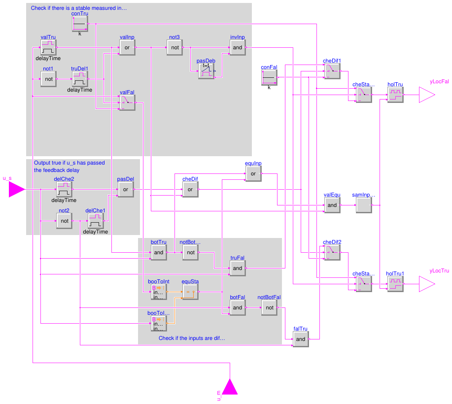
Verify two boolean inputs
Information
Block that compares a boolean set point u_s with
a measured signal u_m and produces two outputs
that may be used to raise alarms about malfunctioning equipment.
The block sets the output yLocFal = true if
the set point is u_s = true but the measured signal is locked
at false, i.e., u_m = false.
Similarly, the block sets the output yLocTru = true
if the set point is u_s = false but the measured signal is locked
at true, i.e., u_m = true.
Hence, any output being true indicates an operational
problem.
To use this block, proceed as follows:
Set the parameter feedbackDelay ≥ 0 to specify how long the
feedback of the controlled device is allowed to take to report
its measured operational signal u_s
after a set point change u_m.
Set the parameter debounce ≥ 0
to specify how long the measured
signal u_m need to remain constant for it to be considered
stable.
Connect the inputs for the set point u_s and
the measured signal u_m to the output signals that need to be checked.
If either output is true, raise an alarm, such as by
connecting instances of
Buildings.Controls.OBC.CDL.Utilities.Assert
to the outputs of this block.
Any output being true indicates a problem.
The block has two timers that each start whenever the corresponding input changes.
One timer, called feedbackDelay+debounce timer, starts
whenever the set point u_s change, and it runs for a time equal to
feedbackDelay+debounce.
The other timer, called debounce timer, starts whenever
the measured signal u_m changes, and it runs for a time equal to
debounce.
The block starts verifying the inputs whenever the feedbackDelay+debounce timer
lapsed, or the debounce timer lapsed,
(and hence the measurement is stable,) whichever is first.
Both outputs being true indicates that the measured signal u_m
is not stable within feedbackDelay+debounce time.
Exactly one output being true indicates
that the measured signal u_m is stable, but
u_s ≠ u_m. In this case,
the block sets yLocFal = true if u_s = true
(the measured signal is locked at false),
or it sets yLocTru = true if u_s = false
(the measured signal is locked at true).
Therefore, exactly one output being true can be interpreted as follows:
Suppose true means on and false means off.
Then, yLocTru = true indicates that an equipment is locked
in operation mode but is commanded off; and similarly,
yLocFal = true indicates that it is locked in off mode
when it is commanded on.
Detailed description
The block works as follows.
Any change in set point u_s starts the feedbackDelay+debounce timer, and
any change in measured signal u_m starts the debounce timer.
As soon as the feedbackDelay+debounce timer
or the debounce timer lapsed,
whichever happens first,
the controller continuously performs these checks:
-
Check for stable measured signal.
Ifu_mis stable, then
goto step 2.
Else:
SetyLocFal = yLocTru = true.
(Equipment is commanded on but we cannot conclude it is running;
set bothtrueto flag an unstable measurement signal.)
-
Check for commanded and measured input to be equal.
Ifu_s ≠ u_m, then
goto step 3.
Else,
setyLocFal = falseandyLocTru = false.
(Equipment is operating as commanded, verified using stable input.) -
Inputs differ.
Ifu_s = true, then
setyLocFal = trueandyLocTru = false.
(The equipment is commanded on, but it is off.)
Else,
setyLocFal = falseandyLocTru = true.
(The equipment is commanded off, but it is on.)
Parameters
| Type | Name | Default | Description |
|---|---|---|---|
| Real | debounce | Time during which input must remain unchanged for signal to considered valid and used in checks [s] | |
| Real | feedbackDelay | Delay after which the two inputs are checked for equality once they become valid [s] |
Connectors
| Type | Name | Description |
|---|---|---|
| input BooleanInput | u_s | Commanded status setpoint |
| input BooleanInput | u_m | Measured status |
| output BooleanOutput | yLocFal | True: measured input is locked to false even after the setpoint has changed to true |
| output BooleanOutput | yLocTru | True: measured input is locked to true even after the setpoint has changed to false |
Modelica definition
 Buildings.Controls.OBC.CDL.Logical.Switch
Switch between two boolean signals
Information
Block that outputs one of two boolean input signals based on a boolean input signal.
If the input signal u2 is true,
the block outputs y = u1.
Otherwise, it outputs y = u3.
Connectors
| Type | Name | Description |
|---|---|---|
| input BooleanInput | u1 | Boolean input signal |
| input BooleanInput | u2 | Boolean switch input signal, if true, y=u1, else y=u3 |
| input BooleanInput | u3 | Boolean input signal |
| output BooleanOutput | y | Booelan output signal |
Modelica definition
 Buildings.Controls.OBC.CDL.Logical.Timer
Timer measuring the time from the time instant where the Boolean input became true
Information
If the Boolean input u is true,
the output y is the time that has elapsed since u became true.
Otherwise, y is 0.
If the output y becomes greater than the threshold time t,
the output passed is true.
Otherwise it is false.
In the limiting case where the timer value reaches the threshold t
and the input u becomes false simultaneously,
the output passed remains false.
Parameters
| Type | Name | Default | Description |
|---|---|---|---|
| Real | t | 0 | Threshold time for comparison [s] |
Connectors
| Type | Name | Description |
|---|---|---|
| input BooleanInput | u | Input that switches timer on if true, and off if false |
| output RealOutput | y | Elapsed time [s] |
| output BooleanOutput | passed | True if the elapsed time is greater than threshold |
Modelica definition
 Buildings.Controls.OBC.CDL.Logical.TimerAccumulating
Accumulating timer that can be reset
Information
Timer that accumulates time until it is reset by an input signal.
If the Boolean input u is true,
the output y is the time that has elapsed while u has been true
since the last time reset became true.
If u is false, the output y holds its value.
If the output y becomes greater than the threshold time t,
the output passed is true.
Otherwise it is false.
When reset becomes true, the timer is reset to 0.
In the limiting case where the timer value reaches the threshold t
and the input u becomes false simultaneously,
the output passed remains false.
Parameters
| Type | Name | Default | Description |
|---|---|---|---|
| Real | t | 0 | Threshold time for comparison [s] |
Connectors
| Type | Name | Description |
|---|---|---|
| input BooleanInput | u | Input that switches timer on if true, and off if false |
| input BooleanInput | reset | Connector for signal that sets timer to zero if it switches to true |
| output RealOutput | y | Elapsed time [s] |
| output BooleanOutput | passed | True if the elapsed time is greater than threshold |
Modelica definition
 Buildings.Controls.OBC.CDL.Logical.Toggle
Toggles output value whenever its input turns true
Information
Block that generates a true output when toggle input u
rises from false to true, provided that the clear input
clr is false or also became at the same time
false. The output remains true until
-
the toggle input
urises fromfalsetotrueagain, or -
the clear input
clrrises fromfalsetotrue.
If the clear input clr is true, the output y
switches to false (if it was true) and it remains false,
regardless of the value of the toggle input u.
At initial time, if clr = false, then the output will be
y = u. Otherwise it will be y=false
(because the clear input clr is true).
Connectors
| Type | Name | Description |
|---|---|---|
| input BooleanInput | u | Toggle input |
| input BooleanInput | clr | Clear input |
| output BooleanOutput | y | Output signal |
Modelica definition
 Buildings.Controls.OBC.CDL.Logical.TriggeredTrapezoid
Triggered trapezoid generator

Information
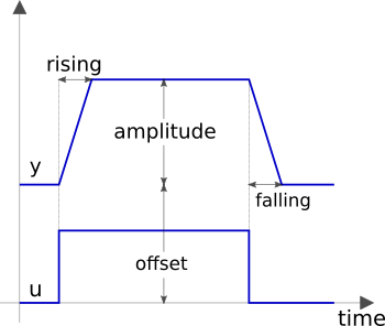
Block that represents a triggered trapezoid.
The block has a Boolean input and a Real
output signal and requires the parameters amplitude,
rising, falling and offset. The
output signal y represents a trapezoidal signal dependent on the
input signal u.
The behaviour is as follows: Assume the initial input to be
false. In this
case, the output will be offset. After a rising edge (i.e., the input
changes from false to true),
the output is rising during rising to the
sum of offset and amplitude. In contrast, after a falling
edge (i.e., the input changes from true to false), the output is falling
during falling to a value of offset.
Note, the case of edges before expiration of rising or falling is handled properly.
Parameters
| Type | Name | Default | Description |
|---|---|---|---|
| Real | amplitude | Amplitude of trapezoid | |
| Real | rising | 0 | Rising duration of trapezoid [s] |
| Real | falling | rising | Falling duration of trapezoid [s] |
| Real | offset | 0 | Offset of output signal |
Connectors
| Type | Name | Description |
|---|---|---|
| input BooleanInput | u | Connector of Boolean input signal |
| output RealOutput | y | Connector of Real output signal |
Modelica definition
 Buildings.Controls.OBC.CDL.Logical.TrueDelay
Delay a rising edge of the input, but do not delay a falling edge.
Information
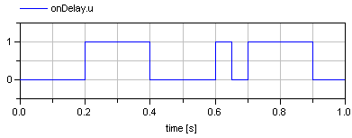
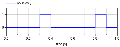
Block that delays a signal when it becomes true.
A rising edge of the Boolean input u gives a delayed output.
A falling edge of the input is immediately given to the output. If
delayOnInit = true, then a true input signal
at the start time is also delayed, otherwise the input signal is
produced immediately at the output.
Simulation results of a typical example with a delay time of 0.1 second is shown below.
Parameters
| Type | Name | Default | Description |
|---|---|---|---|
| Real | delayTime | Delay time [s] | |
| Boolean | delayOnInit | false | Set to true to delay initial true input |
Connectors
| Type | Name | Description |
|---|---|---|
| input BooleanInput | u | Connector of Boolean input signal |
| output BooleanOutput | y | Connector of Boolean output signal |
Modelica definition
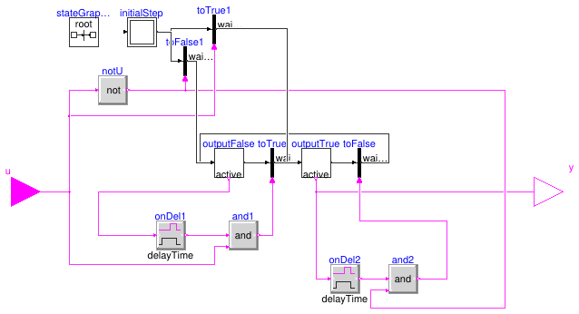
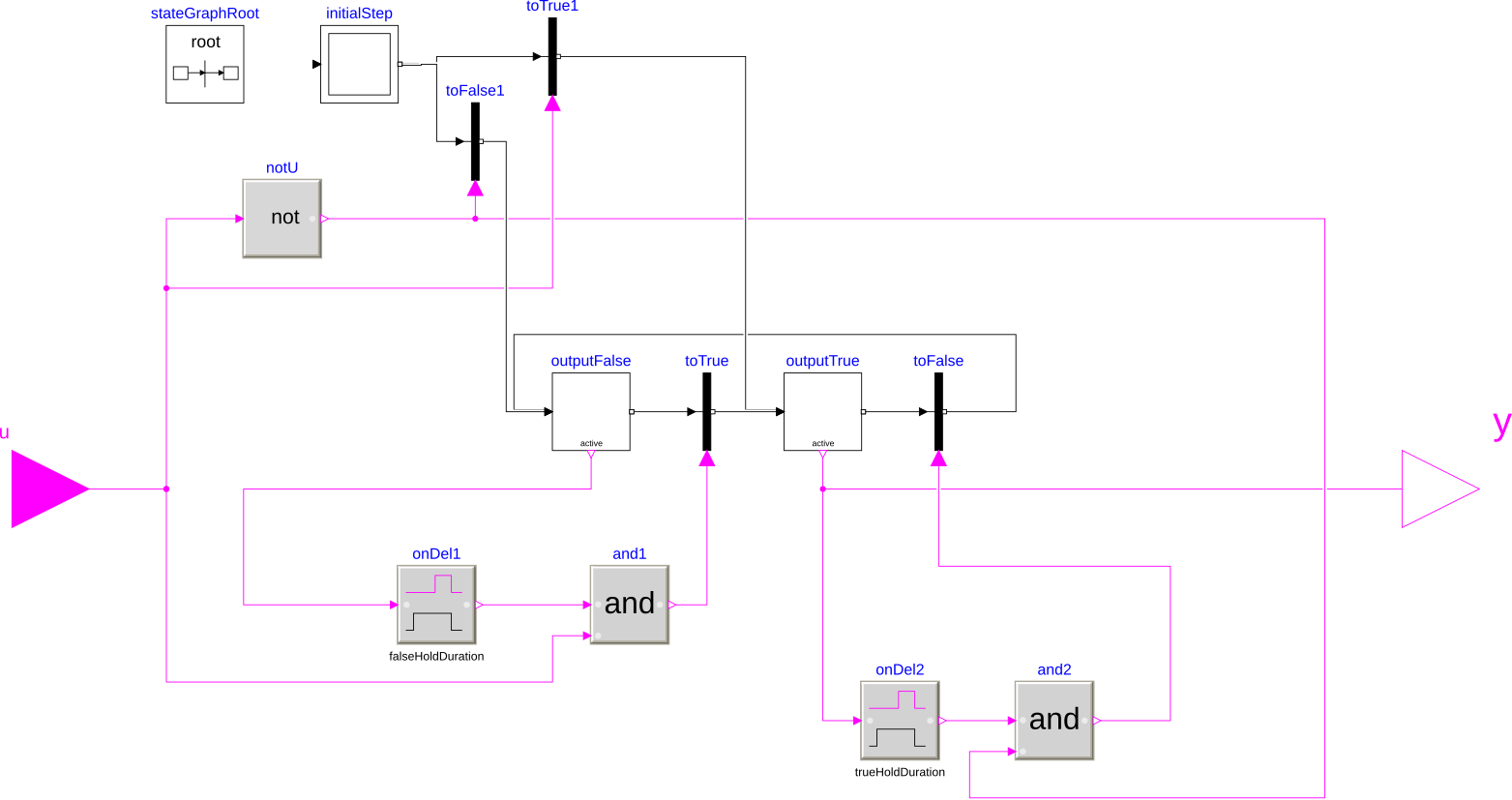
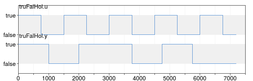
 Buildings.Controls.OBC.CDL.Logical.TrueFalseHold
Block that holds an output signal for at least a specified duration
Information
Block that holds a true or false signal for at least a defined time period.
Whenever the input u switches, the output y
switches and remains at that value for at least duration
seconds, where duration is a parameter.
After duration elapsed, the output will be
y = u.
If this change required changing the value of y,
then y will remain at that value for at least duration.
Otherwise, y will change immediately whenever u
changes.
This block could for example be used to disable an economizer, and not re-enable it for 10 minutes, and vice versa.
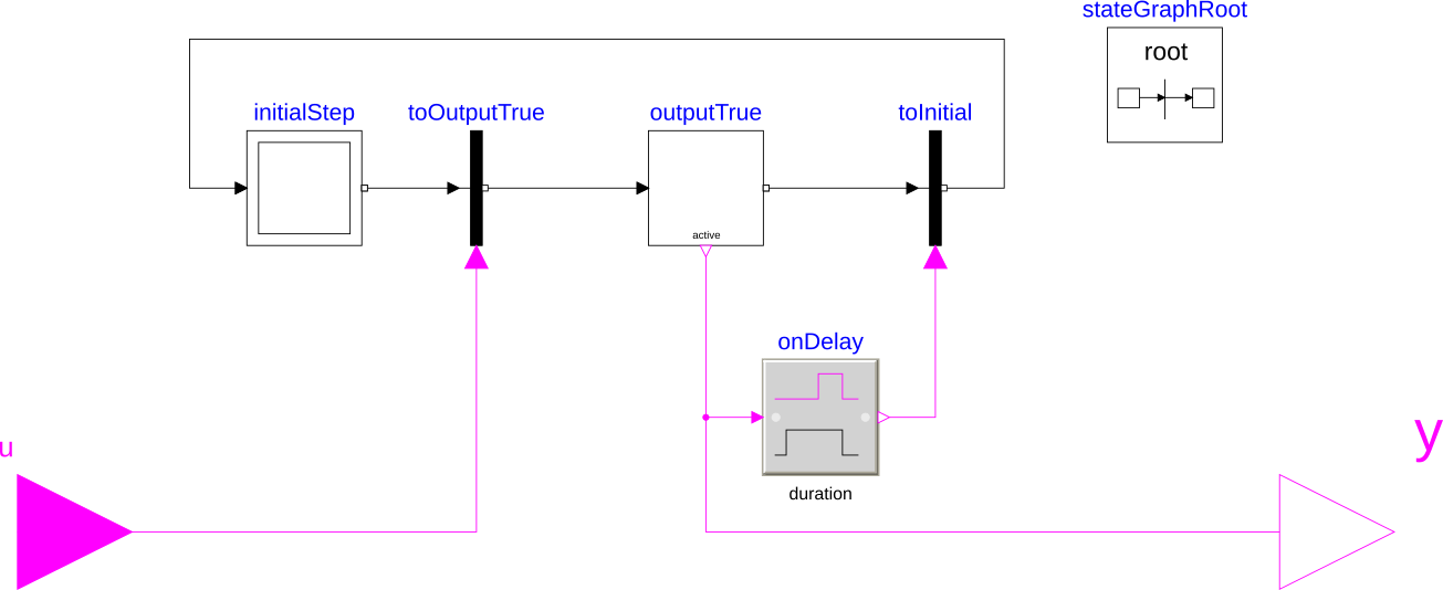
The image below shows the implementation with a state graph in which
each transition is only triggered when the input has the corresponding value,
and the current state has been active for at least duration seconds.
Simulation results of a typical example with duration = 1000 seconds.
Parameters
| Type | Name | Default | Description |
|---|---|---|---|
| Real | trueHoldDuration | true hold duration [s] | |
| Real | falseHoldDuration | trueHoldDuration | false hold duration [s] |
Connectors
| Type | Name | Description |
|---|---|---|
| input BooleanInput | u | Boolean input signal |
| output BooleanOutput | y | Boolean output signal |
Modelica definition
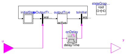
 Buildings.Controls.OBC.CDL.Logical.TrueHoldWithReset
Block that holds a true signal for at least a requested duration
Information
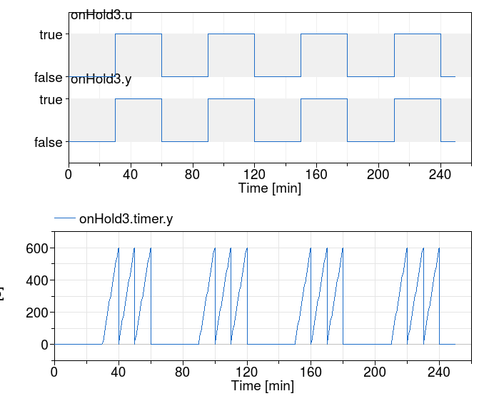
Block that holds a true input signal for at least a defined time period.
At initialization, the output y is equal to the input u.
If the input u becomes true, or is true
during intialization, a timer starts
and the Boolean output y stays true for the time
period provided by the parameter duration.
When this time is elapsed, the input is checked again. If
it is true, then the timer is restarted and the output remains
true for another duration seconds.
If the input u is false after
holdTime seconds, then the ouput is switched to false,
until the input becomes true again.
The figure below shows the state chart of the implementation. Note that the transition are done in zero time.
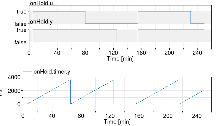
The figure below shows an example with a hold time of 3600 seconds and a pulse width period 9000 seconds that starts at t=200 seconds.
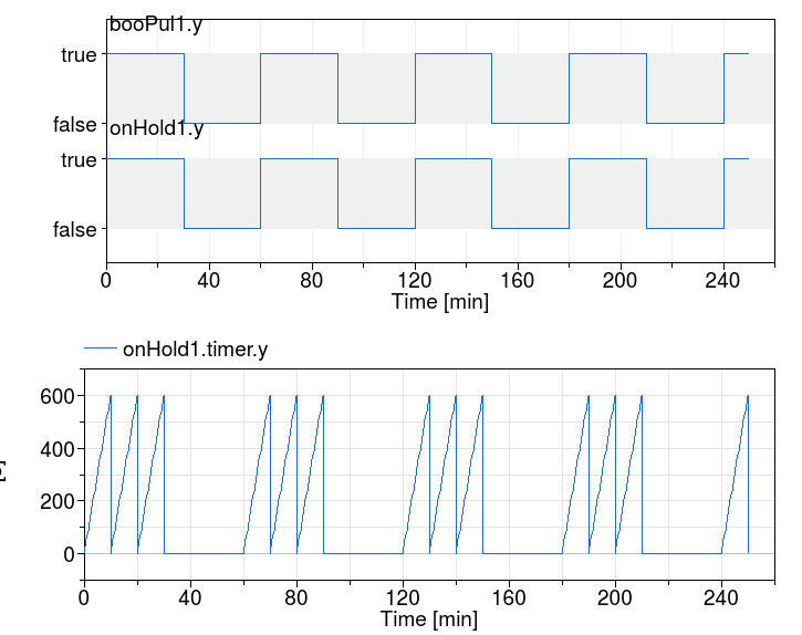
The figure below shows an example with a hold time of 60 seconds and a pulse width period 3600 seconds that starts at t=0 seconds.
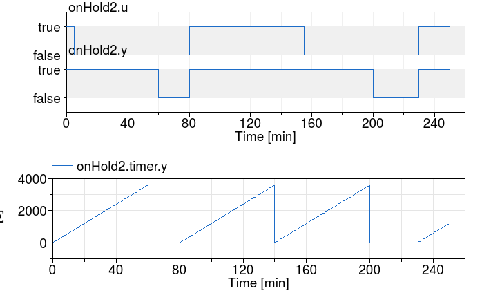
The next two figures show the same experiment, except that the input u
has been negated. The figure below has again a hold time of 3600 seconds
and a pulse width period 9000 seconds that starts at t=200 seconds.
The figure below has again a hold time of 60 seconds and a pulse width period 3600 seconds that starts at t=0 seconds.
Parameters
| Type | Name | Default | Description |
|---|---|---|---|
| Real | duration | Time duration of the true output signal hold [s] |
Connectors
| Type | Name | Description |
|---|---|---|
| input BooleanInput | u | Boolean input signal |
| output BooleanOutput | y | Boolean output signal |
Modelica definition
 Buildings.Controls.OBC.CDL.Logical.VariablePulse
Generate boolean pulse with the width specified by input
Information
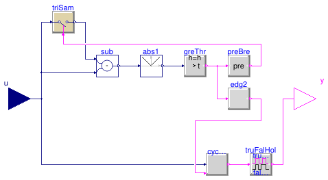
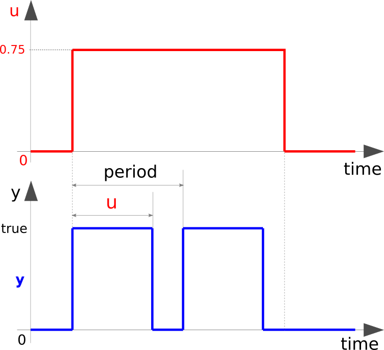
Block that outputs a boolean pulse.
The output of this block is a pulse with a constant period
and a width as obtained from the input 0 ≤ u ≤ 1,
which is the width relative to the period.
The block produces the following ouputs:
-
If
u = 0, the outputyremainsfalse. -
If
0 < u < 1, the outputywill be a boolean pulse with the period specified by the parameterperiodand the width set tou*period. -
If
u = 1, the outputyremainstrue.
When the input u changes by more than deltaU and the output
has been holding constant for more than minimum holding time
minTruFalHol, the output will change to a new pulse with
width equal to u*period.
Parameters
| Type | Name | Default | Description |
|---|---|---|---|
| Real | period | Time for one pulse period [s] | |
| Real | deltaU | 0.01 | Increment of u that triggers recomputation of output [1] |
| Real | minTruFalHol | 0.01*period | Minimum time to hold true or false [s] |
Connectors
| Type | Name | Description |
|---|---|---|
| input RealInput | u | Ratio of the period that the output should be true [1] |
| output BooleanOutput | y | Boolean pulse when the input is greater than zero |
Modelica definition
Buildings.Controls.OBC.CDL.Logical.Xor
Logical 'xor': y = u1 xor u2
Information
Block that outputs true if exactly one input is true.
Otherwise the output is false.
Connectors
| Type | Name | Description |
|---|---|---|
| input BooleanInput | u1 | Connector of first Boolean input signal |
| input BooleanInput | u2 | Connector of second Boolean input signal |
| output BooleanOutput | y | Connector of Boolean output signal |
Modelica definition
 Buildings.Controls.OBC.CDL.Logical.ZeroCrossing
Trigger zero crossing of input u
Information
Block that detects zero crossings.
The output y is true at the
time instant when the input u becomes
zero, provided the input enable is
true. At all other time instants,
the output y is false.
If the input u is zero at a time instant when
the enable
input changes its value, then the output y is false.
Note, that in the plot window of a Modelica simulator, the output of
this block is usually identically to false, because the output
may only be true at an event instant, but not during
continuous integration. In order to check that this component is
actually working as expected, one should connect its output to, e.g.,
component Buildings.Controls.OBC.CDL.Discrete.TriggeredSampler.
Connectors
| Type | Name | Description |
|---|---|---|
| input RealInput | u | Connector of Real input signal |
| output BooleanOutput | y | Connector of Boolean output signal |
| input BooleanInput | enable | Zero input crossing is triggered if the enable input signal is true |
Modelica definition
 Buildings.Controls.OBC.CDL.Logical.VariablePulse.Cycle
Generate boolean pulse with the width specified by the input
Parameters
| Type | Name | Default | Description |
|---|---|---|---|
| Real | period | Time for one pulse period [s] | |
| Real | minTruFalHol | Minimum time to hold true or false [s] |
Connectors
| Type | Name | Description |
|---|---|---|
| input BooleanInput | go | True: cycle the output |
| input RealInput | u | Ratio of the period that the output should be true |
| output BooleanOutput | y | Cycling boolean output |