Buildings.Experimental.DHC.Loads.BaseClasses.Validation.BaseClasses
Package with base classes
Information
This package contains base classes that are used to construct the classes in Buildings.Experimental.DHC.Loads.BaseClasses.Validation.
Extends from Modelica.Icons.BasesPackage (Icon for packages containing base classes).
Package Content
| Name | Description |
|---|---|
| Dummy building model for validation purposes | |
| Dummy building with ETS model for validation purposes | |
| Dummy ETS model for validation purposes | |
| Model of a sensible only two-pipe fan coil unit for cooling, computing a required chilled water mass flow rate | |
| Model of a two-pipe fan coil unit for heating, computing a required heating water mass flow rate | |
| Model of a two-pipe fan coil unit for heating, with a two-way control valve |
 Buildings.Experimental.DHC.Loads.BaseClasses.Validation.BaseClasses.Building
Dummy building model for validation purposes
Information
This is a minimum example of a class extending Buildings.Experimental.DHC.Loads.BaseClasses.PartialBuilding developed for testing purposes only.
Extends from Buildings.Experimental.DHC.Loads.BaseClasses.PartialBuilding (Partial class for building model).
Parameters
| Type | Name | Default | Description |
|---|---|---|---|
| replaceable package Medium | Water | Medium in the building distribution system | |
| MassFlowRate | m_flow_nominal | Nominal mass flow rate [kg/s] | |
| Configuration | |||
| Boolean | have_heaWat | false | Set to true if the building has heating water system |
| Boolean | have_chiWat | false | Set to true if the building has chilled water system |
| Boolean | have_eleHea | false | Set to true if the building has decentralized electric heating system |
| Boolean | have_eleCoo | false | Set to true if the building has decentralized electric cooling system |
| Boolean | have_fan | false | Set to true if fan power is computed |
| Boolean | have_pum | false | Set to true if pump power is computed |
| Boolean | have_weaBus | false | Set to true to use a weather bus |
| Scaling | |||
| Real | facMul | 1 | Multiplier factor |
| Nominal condition | |||
| HeatFlowRate | QChiWat_flow_nominal | Design heat flow rate for chilled water production (<0) [W] | |
| HeatFlowRate | QHeaWat_flow_nominal | Design heat flow rate for heating water production (>0) [W] | |
| Assumptions | |||
| Boolean | allowFlowReversal | false | = true to allow flow reversal, false restricts to design direction (port_a -> port_b) |
Connectors
| Type | Name | Description |
|---|---|---|
| Bus | weaBus | Weather data bus |
| FluidPorts_a | ports_aHeaWat[nPorts_aHeaWat] | Heating water inlet ports |
| FluidPorts_b | ports_bHeaWat[nPorts_bHeaWat] | Heating water outlet ports |
| FluidPorts_a | ports_aChiWat[nPorts_aChiWat] | Chilled water inlet ports |
| FluidPorts_b | ports_bChiWat[nPorts_bChiWat] | Chilled water outlet ports |
| output RealOutput | QHea_flow | Total heating heat flow rate transferred to the loads (>=0) [W] |
| output RealOutput | QCoo_flow | Total cooling heat flow rate transferred to the loads (<=0) [W] |
| output RealOutput | PHea | Power drawn by decentralized heating system [W] |
| output RealOutput | PCoo | Power drawn by decentralized cooling system [W] |
| output RealOutput | PFan | Power drawn by fan motors [W] |
| output RealOutput | PPum | Power drawn by pump motors [W] |
Modelica definition
 Buildings.Experimental.DHC.Loads.BaseClasses.Validation.BaseClasses.BuildingWithETS
Dummy building with ETS model for validation purposes
Information
This is a minimum example of a class extending Buildings.Experimental.DHC.Loads.BaseClasses.PartialBuildingWithPartialETS developed for testing purposes only.
Extends from Buildings.Experimental.DHC.Loads.BaseClasses.PartialBuildingWithPartialETS (Partial model of a building with an energy transfer station).
Parameters
| Type | Name | Default | Description |
|---|---|---|---|
| replaceable package MediumSer | Water | Service side medium | |
| replaceable package MediumSerHea_a | Water | Service side medium at heating inlet | |
| replaceable package MediumBui | Water | Building side medium | |
| Configuration | |||
| Integer | nPorts_heaWat | 0 | Number of heating water fluid ports |
| Integer | nPorts_chiWat | 0 | Number of chilled water fluid ports |
| Scaling | |||
| Real | facMul | 1 | Multiplier factor |
| Assumptions | |||
| Boolean | allowFlowReversalSer | false | Set to true to allow flow reversal on service side |
| Boolean | allowFlowReversalBui | false | Set to true to allow flow reversal on building side |
Connectors
| Type | Name | Description |
|---|---|---|
| FluidPort_a | port_aSerAmb | Fluid connector for ambient water service supply line |
| FluidPort_b | port_bSerAmb | Fluid connector for ambient water service return line |
| FluidPort_a | port_aSerHea | Fluid connector for heating service supply line |
| FluidPort_b | port_bSerHea | Fluid connector for heating service return line |
| FluidPort_a | port_aSerCoo | Fluid connector for cooling service supply line |
| FluidPort_b | port_bSerCoo | Fluid connector for cooling service return line |
| Bus | weaBus | Weather data bus |
| output RealOutput | QHea_flow | Total heating heat flow rate transferred to the loads (>=0) [W] |
| output RealOutput | QCoo_flow | Total cooling heat flow rate transferred to the loads (<=0) [W] |
| output RealOutput | PHea | Power drawn by heating system [W] |
| output RealOutput | PCoo | Power drawn by cooling system [W] |
| output RealOutput | PFan | Power drawn by fan motors [W] |
| output RealOutput | PPum | Power drawn by pump motors [W] |
| output RealOutput | QFue_flow[nFue] | Fuel energy input rate [W] |
Modelica definition
 Buildings.Experimental.DHC.Loads.BaseClasses.Validation.BaseClasses.ETS
Dummy ETS model for validation purposes
Information
This is a minimum example of a class extending Buildings.Experimental.DHC.EnergyTransferStations.BaseClasses.PartialETS developed for testing purposes only.
Extends from Buildings.Experimental.DHC.EnergyTransferStations.BaseClasses.PartialETS (Partial class for modeling an energy transfer station).
Parameters
| Type | Name | Default | Description |
|---|---|---|---|
| replaceable package MediumSer | Water | Service side medium | |
| replaceable package MediumSerHea_a | Water | Service side medium at heating inlet | |
| replaceable package MediumBui | Water | Building side medium | |
| Generic | fue[nFue] | Fuel type | |
| MassFlowRate | m_flow_nominal | Nominal mass flow rate [kg/s] | |
| Configuration | |||
| DistrictSystemType | typ | TypDisSys.CombinedGeneration... | Type of district system |
| Boolean | have_heaWat | false | Set to true if the ETS supplies heating water |
| Boolean | have_hotWat | false | Set to true if the ETS supplies hot water |
| Boolean | have_chiWat | false | Set to true if the ETS supplies chilled water |
| Boolean | have_fan | false | Set to true if fan power is computed |
| Boolean | have_pum | false | Set to true if pump power is computed |
| Boolean | have_eleHea | false | Set to true if the ETS has electric heating system |
| Integer | nFue | 0 | Number of fuel types (0 means no combustion system) |
| Boolean | have_eleCoo | false | Set to true if the ETS has electric cooling system |
| Boolean | have_weaBus | false | Set to true to use a weather bus |
| Nominal condition | |||
| HeatFlowRate | QHeaWat_flow_nominal | 0 | Nominal capacity of heating system (>=0) [W] |
| HeatFlowRate | QHotWat_flow_nominal | 0 | Nominal capacity of hot water production system (>=0) [W] |
| HeatFlowRate | QChiWat_flow_nominal | 0 | Nominal capacity of cooling system (<=0) [W] |
| Assumptions | |||
| Boolean | allowFlowReversalSer | false | Set to true to allow flow reversal on service side |
| Boolean | allowFlowReversalBui | false | Set to true to allow flow reversal on building side |
Connectors
| Type | Name | Description |
|---|---|---|
| FluidPorts_a | ports_aHeaWat[nPorts_aHeaWat] | Fluid connectors for heating water return (from building) |
| FluidPorts_b | ports_bHeaWat[nPorts_bHeaWat] | Fluid connectors for heating water supply (to building) |
| FluidPorts_a | ports_aChiWat[nPorts_aChiWat] | Fluid connectors for chilled water return (from building) |
| FluidPorts_b | ports_bChiWat[nPorts_bChiWat] | Fluid connectors for chilled water supply (to building) |
| FluidPort_a | port_aSerAmb | Fluid connector for ambient water service supply line |
| FluidPort_b | port_bSerAmb | Fluid connector for ambient water service return line |
| FluidPort_a | port_aSerHea | Fluid connector for heating service supply line |
| FluidPort_b | port_bSerHea | Fluid connector for heating service return line |
| FluidPort_a | port_aSerCoo | Fluid connector for cooling service supply line |
| FluidPort_b | port_bSerCoo | Fluid connector for cooling service return line |
| output RealOutput | PHea | Power drawn by heating system [W] |
| output RealOutput | PCoo | Power drawn by cooling system [W] |
| output RealOutput | PFan | Power drawn by fan motors [W] |
| output RealOutput | PPum | Power drawn by pump motors [W] |
| output RealOutput | QFue_flow[nFue] | Fuel energy input rate [W] |
| Bus | weaBus | Weather data bus |
Modelica definition
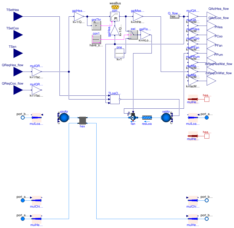
 Buildings.Experimental.DHC.Loads.BaseClasses.Validation.BaseClasses.FanCoil2PipeCooling
Model of a sensible only two-pipe fan coil unit for cooling,
computing a required chilled water mass flow rate
Information
This is a simplified model of a two-pipe fan coil unit for cooling. It is intended to be used
- in a case where the room thermal loads are provided as time series: it therefore takes the load as an input, and
- in conjunction with Buildings.Experimental.DHC.Loads.BaseClasses.FlowDistribution: it therefore computes the water mass flow rate required to meet the load.
For the sake of computational performance, a PI controller is used instead of an inverse model of the heat exchanger to assess the required water mass flow rate. The controller output signal is mapped linearly to both,
- the water mass flow rate, from zero to its nominal value, and
- the air mass flow rate, from zero to its nominal value.
The controller tracks the load while the impact of an unmet load on the room air temperature is assessed with Buildings.Experimental.DHC.Loads.BaseClasses.SimpleRoomODE.
Extends from Buildings.Experimental.DHC.Loads.BaseClasses.PartialTerminalUnit (Partial model for HVAC terminal unit).
Parameters
| Type | Name | Default | Description |
|---|---|---|---|
| replaceable package Medium1 | Water | Medium in the building distribution system | |
| replaceable package Medium2 | Air | Load side medium | |
| Real | k | 1 | Gain of controller |
| Time | Ti | 10 | Time constant of integrator block [s] |
| Scaling | |||
| Real | facMul | 1 | Multiplier factor |
| Real | facMulZon | 1 | Zone multiplier factor |
| Configuration | |||
| Boolean | have_heaWat | false | Set to true if the system uses heating water |
| Boolean | have_chiWat | true | Set to true if the system uses chilled water |
| Boolean | have_chaOve | false | Set to true if the chilled water based heat exchanger operates in change-over |
| Boolean | have_eleHea | false | Set to true if the system has electric heating system |
| Boolean | have_eleCoo | false | Set to true if the system has electric cooling system |
| Boolean | have_heaPor | false | Set to true for heat ports on the load side |
| Boolean | have_fluPor | false | Set to true for fluid ports on the load side |
| Boolean | have_TSen | false | Set to true for measured temperature as an input |
| Boolean | have_QReq_flow | true | Set to true for required heat flow rate as an input |
| Boolean | have_weaBus | false | Set to true to use a weather bus |
| Boolean | have_fan | true | Set to true if fan power is computed |
| Boolean | have_pum | false | Set to true if pump power is computed |
| Boolean | have_speVar | true | Set to true for a variable speed fan (otherwise fan is always on) |
| Nominal condition | |||
| HeatFlowRate | QHea_flow_nominal | 0 | Nominal heating capacity (>=0) [W] |
| HeatFlowRate | QCoo_flow_nominal | 0 | Nominal cooling capacity (<=0) [W] |
| MassFlowRate | mHeaWat_flow_nominal | 0 | Heating water mass flow rate at nominal conditions [kg/s] |
| MassFlowRate | mChiWat_flow_nominal | abs(QCoo_flow_nominal/cpChiW... | Chilled water mass flow rate at nominal conditions [kg/s] |
| MassFlowRate | mLoaHea_flow_nominal | 0 | Load side mass flow rate at nominal conditions in heating mode [kg/s] |
| MassFlowRate | mLoaCoo_flow_nominal | 0 | Load side mass flow rate at nominal conditions in cooling mode [kg/s] |
| Temperature | T_aHeaWat_nominal | 273.15 + 60 | Heating water inlet temperature at nominal conditions [K] |
| Temperature | T_bHeaWat_nominal | T_aHeaWat_nominal - 22.2 | Heating water outlet temperature at nominal conditions [K] |
| Temperature | T_aChiWat_nominal | 273.15 + 7.2 | Chilled water inlet temperature at nominal conditions [K] |
| Temperature | T_bChiWat_nominal | T_aChiWat_nominal + 5.6 | Chilled water outlet temperature at nominal conditions [K] |
| Temperature | T_aLoaHea_nominal | 273.15 + 21.1 | Load side inlet temperature at nominal conditions in heating mode [K] |
| Temperature | T_aLoaCoo_nominal | 273.15 + 26.7 | Load side inlet temperature at nominal conditions in cooling mode [K] |
| MassFraction | w_aLoaCoo_nominal | 0.011 | Load side inlet humidity ratio at nominal conditions in cooling mode [1] |
| PressureDifference | dpLoa_nominal | 250 | Load side pressure drop [Pa] |
| HeatFlowRate | QEnv_flow_nominal | Nominal envelope heat loss (for room air temperature prediction) [W] | |
| TemperatureDifference | dTEnv_nominal | 15 | Design temperature difference at which envelope heat loss is QEnv_flow_nominal [K] |
| Assumptions | |||
| Boolean | allowFlowReversal | false | Set to true to allow flow reversal in building distribution system |
| Boolean | allowFlowReversalLoa | false | Set to true to allow flow reversal on the load side |
Connectors
| Type | Name | Description |
|---|---|---|
| replaceable package Medium1 | Medium in the building distribution system | |
| replaceable package Medium2 | Load side medium | |
| input RealInput | TSen | Temperature (measured) [K] |
| input RealInput | TSetHea | Heating set point [K] |
| input RealInput | TSetCoo | Cooling set point [K] |
| input RealInput | QReqHea_flow | Required heat flow rate to meet heating set point (>=0) [W] |
| input RealInput | QReqCoo_flow | Required heat flow rate to meet cooling set point (<=0) [W] |
| output RealOutput | QActHea_flow | Heating heat flow rate transferred to the load (>=0) [W] |
| output RealOutput | QActCoo_flow | Cooling heat flow rate transferred to the load (<=0) [W] |
| output RealOutput | PHea | Power drawn by heating system [W] |
| output RealOutput | PCoo | Power drawn by cooling system [W] |
| output RealOutput | PFan | Power drawn by fans motors [W] |
| output RealOutput | PPum | Power drawn by pumps motors [W] |
| output RealOutput | mReqHeaWat_flow | Required heating water flow rate to meet heating set point [kg/s] |
| output RealOutput | mReqChiWat_flow | Required chilled water flow rate to meet cooling set point [kg/s] |
| FluidPort_a | port_aLoa | Fluid stream inlet port on the load side |
| FluidPort_b | port_bLoa | Fluid stream outlet port on the load side |
| HeatPort_b | heaPorCon | Heat port transferring convective heat to the load |
| HeatPort_b | heaPorRad | Heat port transferring radiative heat to the load |
| Bus | weaBus | Weather data bus |
| FluidPort_a | port_aHeaWat | Heating water inlet port |
| FluidPort_a | port_aChiWat | Chilled water inlet port |
| FluidPort_b | port_bHeaWat | Heating water outlet port |
| FluidPort_b | port_bChiWat | Chilled water outlet port |
Modelica definition
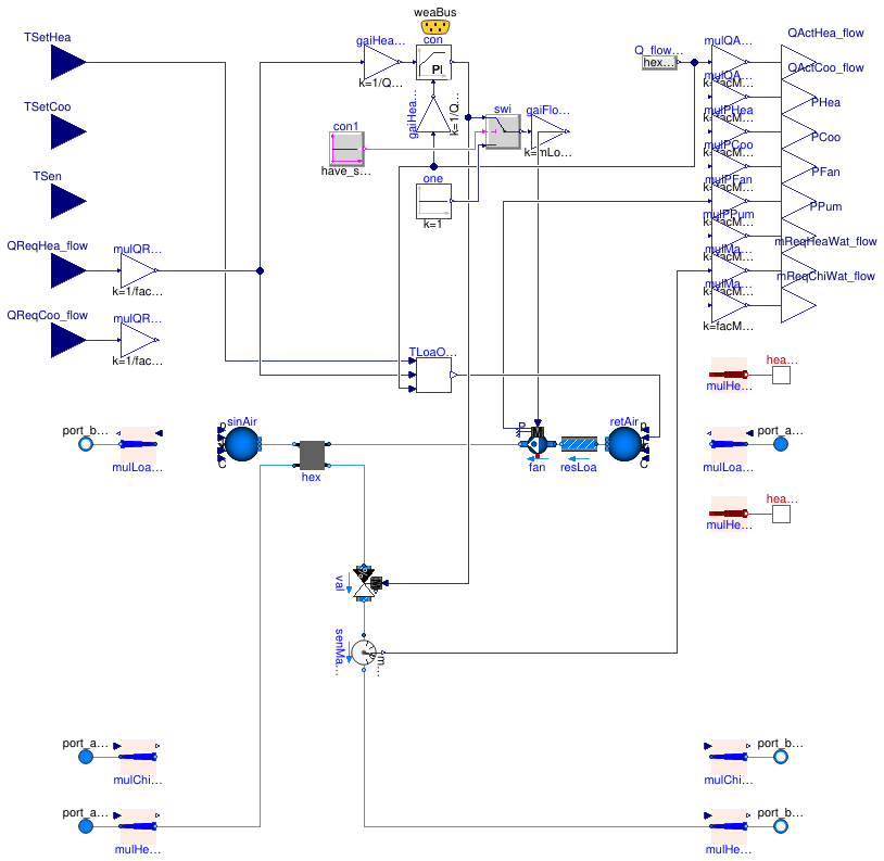
 Buildings.Experimental.DHC.Loads.BaseClasses.Validation.BaseClasses.FanCoil2PipeHeating
Model of a two-pipe fan coil unit for heating,
computing a required heating water mass flow rate
Information
This is a simplified model of a two-pipe fan coil unit for heating. It is intended to be used
- in a case where the room thermal loads are provided as time series: it therefore takes the load as an input, and
- in conjunction with Buildings.Experimental.DHC.Loads.BaseClasses.FlowDistribution: it therefore computes the water mass flow rate required to meet the load.
For the sake of computational performance, a PI controller is used instead of an inverse model of the heat exchanger to assess the required water mass flow rate. The controller output signal is mapped linearly to both,
- the water mass flow rate, from zero to its nominal value, and
- the air mass flow rate, from zero to its nominal value.
The controller tracks the load while the impact of an unmet load on the room air temperature is assessed with Buildings.Experimental.DHC.Loads.BaseClasses.SimpleRoomODE.
Extends from Buildings.Experimental.DHC.Loads.BaseClasses.PartialTerminalUnit (Partial model for HVAC terminal unit).
Parameters
| Type | Name | Default | Description |
|---|---|---|---|
| replaceable package Medium1 | Water | Medium in the building distribution system | |
| replaceable package Medium2 | Air | Load side medium | |
| Real | k | 1 | Gain of controller |
| Time | Ti | 10 | Time constant of integrator block [s] |
| Scaling | |||
| Real | facMul | 1 | Multiplier factor |
| Real | facMulZon | 1 | Zone multiplier factor |
| Configuration | |||
| Boolean | have_heaWat | true | Set to true if the system uses heating water |
| Boolean | have_chiWat | false | Set to true if the system uses chilled water |
| Boolean | have_chaOve | false | Set to true if the chilled water based heat exchanger operates in change-over |
| Boolean | have_eleHea | false | Set to true if the system has electric heating system |
| Boolean | have_eleCoo | false | Set to true if the system has electric cooling system |
| Boolean | have_heaPor | false | Set to true for heat ports on the load side |
| Boolean | have_fluPor | false | Set to true for fluid ports on the load side |
| Boolean | have_TSen | false | Set to true for measured temperature as an input |
| Boolean | have_QReq_flow | true | Set to true for required heat flow rate as an input |
| Boolean | have_weaBus | false | Set to true to use a weather bus |
| Boolean | have_fan | true | Set to true if fan power is computed |
| Boolean | have_pum | false | Set to true if pump power is computed |
| Boolean | have_speVar | true | Set to true for a variable speed fan (otherwise fan is always on) |
| Nominal condition | |||
| HeatFlowRate | QHea_flow_nominal | 0 | Nominal heating capacity (>=0) [W] |
| HeatFlowRate | QCoo_flow_nominal | 0 | Nominal cooling capacity (<=0) [W] |
| MassFlowRate | mHeaWat_flow_nominal | abs(QHea_flow_nominal/cpHeaW... | Heating water mass flow rate at nominal conditions [kg/s] |
| MassFlowRate | mChiWat_flow_nominal | 0 | Chilled water mass flow rate at nominal conditions [kg/s] |
| MassFlowRate | mLoaHea_flow_nominal | 0 | Load side mass flow rate at nominal conditions in heating mode [kg/s] |
| MassFlowRate | mLoaCoo_flow_nominal | 0 | Load side mass flow rate at nominal conditions in cooling mode [kg/s] |
| Temperature | T_aHeaWat_nominal | 273.15 + 60 | Heating water inlet temperature at nominal conditions [K] |
| Temperature | T_bHeaWat_nominal | T_aHeaWat_nominal - 22.2 | Heating water outlet temperature at nominal conditions [K] |
| Temperature | T_aChiWat_nominal | 273.15 + 7.2 | Chilled water inlet temperature at nominal conditions [K] |
| Temperature | T_bChiWat_nominal | T_aChiWat_nominal + 5.6 | Chilled water outlet temperature at nominal conditions [K] |
| Temperature | T_aLoaHea_nominal | 273.15 + 21.1 | Load side inlet temperature at nominal conditions in heating mode [K] |
| Temperature | T_aLoaCoo_nominal | 273.15 + 26.7 | Load side inlet temperature at nominal conditions in cooling mode [K] |
| MassFraction | w_aLoaCoo_nominal | 0.011 | Load side inlet humidity ratio at nominal conditions in cooling mode [1] |
| PressureDifference | dpLoa_nominal | 250 | Load side pressure drop [Pa] |
| Assumptions | |||
| Boolean | allowFlowReversal | false | Set to true to allow flow reversal in building distribution system |
| Boolean | allowFlowReversalLoa | false | Set to true to allow flow reversal on the load side |
Connectors
| Type | Name | Description |
|---|---|---|
| replaceable package Medium1 | Medium in the building distribution system | |
| replaceable package Medium2 | Load side medium | |
| input RealInput | TSen | Temperature (measured) [K] |
| input RealInput | TSetHea | Heating set point [K] |
| input RealInput | TSetCoo | Cooling set point [K] |
| input RealInput | QReqHea_flow | Required heat flow rate to meet heating set point (>=0) [W] |
| input RealInput | QReqCoo_flow | Required heat flow rate to meet cooling set point (<=0) [W] |
| output RealOutput | QActHea_flow | Heating heat flow rate transferred to the load (>=0) [W] |
| output RealOutput | QActCoo_flow | Cooling heat flow rate transferred to the load (<=0) [W] |
| output RealOutput | PHea | Power drawn by heating system [W] |
| output RealOutput | PCoo | Power drawn by cooling system [W] |
| output RealOutput | PFan | Power drawn by fans motors [W] |
| output RealOutput | PPum | Power drawn by pumps motors [W] |
| output RealOutput | mReqHeaWat_flow | Required heating water flow rate to meet heating set point [kg/s] |
| output RealOutput | mReqChiWat_flow | Required chilled water flow rate to meet cooling set point [kg/s] |
| FluidPort_a | port_aLoa | Fluid stream inlet port on the load side |
| FluidPort_b | port_bLoa | Fluid stream outlet port on the load side |
| HeatPort_b | heaPorCon | Heat port transferring convective heat to the load |
| HeatPort_b | heaPorRad | Heat port transferring radiative heat to the load |
| Bus | weaBus | Weather data bus |
| FluidPort_a | port_aHeaWat | Heating water inlet port |
| FluidPort_a | port_aChiWat | Chilled water inlet port |
| FluidPort_b | port_bHeaWat | Heating water outlet port |
| FluidPort_b | port_bChiWat | Chilled water outlet port |
Modelica definition
 Buildings.Experimental.DHC.Loads.BaseClasses.Validation.BaseClasses.FanCoil2PipeHeatingValve
Model of a two-pipe fan coil unit for heating, with a two-way control valve
Information
This is a simplified model of a two-pipe fan coil unit for heating. It is intended to be used in a case where the room thermal loads are provided as time series, and hence it takes the load as an input.
A PI controller tracks the load. The controller output signal is mapped linearly to both,
- the opening of a two-way control valve, and
- the air mass flow rate, from zero to its nominal value.
The impact of an unmet load on the room air temperature is assessed with Buildings.Experimental.DHC.Loads.BaseClasses.SimpleRoomODE.
Extends from Buildings.Experimental.DHC.Loads.BaseClasses.PartialTerminalUnit (Partial model for HVAC terminal unit).
Parameters
| Type | Name | Default | Description |
|---|---|---|---|
| replaceable package Medium1 | Water | Medium in the building distribution system | |
| replaceable package Medium2 | Air | Load side medium | |
| Boolean | have_speVar | true | Set to true for a variable speed fan (otherwise fan is always on) |
| PressureDifference | dpSou_nominal | 30000 | Nominal pressure drop on source side [Pa] |
| Scaling | |||
| Real | facMul | 1 | Multiplier factor |
| Real | facMulZon | 1 | Zone multiplier factor |
| Configuration | |||
| Boolean | have_heaWat | true | Set to true if the system uses heating water |
| Boolean | have_chiWat | false | Set to true if the system uses chilled water |
| Boolean | have_chaOve | false | Set to true if the chilled water based heat exchanger operates in change-over |
| Boolean | have_eleHea | false | Set to true if the system has electric heating system |
| Boolean | have_eleCoo | false | Set to true if the system has electric cooling system |
| Boolean | have_heaPor | false | Set to true for heat ports on the load side |
| Boolean | have_fluPor | false | Set to true for fluid ports on the load side |
| Boolean | have_TSen | false | Set to true for measured temperature as an input |
| Boolean | have_QReq_flow | true | Set to true for required heat flow rate as an input |
| Boolean | have_weaBus | false | Set to true to use a weather bus |
| Boolean | have_fan | true | Set to true if fan power is computed |
| Boolean | have_pum | false | Set to true if pump power is computed |
| Nominal condition | |||
| HeatFlowRate | QHea_flow_nominal | 0 | Nominal heating capacity (>=0) [W] |
| HeatFlowRate | QCoo_flow_nominal | 0 | Nominal cooling capacity (<=0) [W] |
| MassFlowRate | mHeaWat_flow_nominal | abs(QHea_flow_nominal/cpHeaW... | Heating water mass flow rate at nominal conditions [kg/s] |
| MassFlowRate | mChiWat_flow_nominal | 0 | Chilled water mass flow rate at nominal conditions [kg/s] |
| MassFlowRate | mLoaHea_flow_nominal | 0 | Load side mass flow rate at nominal conditions in heating mode [kg/s] |
| MassFlowRate | mLoaCoo_flow_nominal | 0 | Load side mass flow rate at nominal conditions in cooling mode [kg/s] |
| Temperature | T_aHeaWat_nominal | 273.15 + 60 | Heating water inlet temperature at nominal conditions [K] |
| Temperature | T_bHeaWat_nominal | T_aHeaWat_nominal - 22.2 | Heating water outlet temperature at nominal conditions [K] |
| Temperature | T_aChiWat_nominal | 273.15 + 7.2 | Chilled water inlet temperature at nominal conditions [K] |
| Temperature | T_bChiWat_nominal | T_aChiWat_nominal + 5.6 | Chilled water outlet temperature at nominal conditions [K] |
| Temperature | T_aLoaHea_nominal | 273.15 + 21.1 | Load side inlet temperature at nominal conditions in heating mode [K] |
| Temperature | T_aLoaCoo_nominal | 273.15 + 26.7 | Load side inlet temperature at nominal conditions in cooling mode [K] |
| MassFraction | w_aLoaCoo_nominal | 0.011 | Load side inlet humidity ratio at nominal conditions in cooling mode [1] |
| PressureDifference | dpLoa_nominal | 250 | Load side pressure drop [Pa] |
| Assumptions | |||
| Boolean | allowFlowReversal | false | Set to true to allow flow reversal in building distribution system |
| Boolean | allowFlowReversalLoa | false | Set to true to allow flow reversal on the load side |
Connectors
| Type | Name | Description |
|---|---|---|
| replaceable package Medium1 | Medium in the building distribution system | |
| replaceable package Medium2 | Load side medium | |
| input RealInput | TSen | Temperature (measured) [K] |
| input RealInput | TSetHea | Heating set point [K] |
| input RealInput | TSetCoo | Cooling set point [K] |
| input RealInput | QReqHea_flow | Required heat flow rate to meet heating set point (>=0) [W] |
| input RealInput | QReqCoo_flow | Required heat flow rate to meet cooling set point (<=0) [W] |
| output RealOutput | QActHea_flow | Heating heat flow rate transferred to the load (>=0) [W] |
| output RealOutput | QActCoo_flow | Cooling heat flow rate transferred to the load (<=0) [W] |
| output RealOutput | PHea | Power drawn by heating system [W] |
| output RealOutput | PCoo | Power drawn by cooling system [W] |
| output RealOutput | PFan | Power drawn by fans motors [W] |
| output RealOutput | PPum | Power drawn by pumps motors [W] |
| output RealOutput | mReqHeaWat_flow | Required heating water flow rate to meet heating set point [kg/s] |
| output RealOutput | mReqChiWat_flow | Required chilled water flow rate to meet cooling set point [kg/s] |
| FluidPort_a | port_aLoa | Fluid stream inlet port on the load side |
| FluidPort_b | port_bLoa | Fluid stream outlet port on the load side |
| HeatPort_b | heaPorCon | Heat port transferring convective heat to the load |
| HeatPort_b | heaPorRad | Heat port transferring radiative heat to the load |
| Bus | weaBus | Weather data bus |
| FluidPort_a | port_aHeaWat | Heating water inlet port |
| FluidPort_a | port_aChiWat | Chilled water inlet port |
| FluidPort_b | port_bHeaWat | Heating water outlet port |
| FluidPort_b | port_bChiWat | Chilled water outlet port |