Buildings.Experimental.DHC.EnergyTransferStations.Combined.Controls
Package of control blocks for fifth generation DHC ETS
Information
This package contains control blocks for energy transfer stations in fifth generation district heating and cooling systems.
Extends from Modelica.Icons.VariantsPackage (Icon for package containing variants).
Package Content
| Name | Description |
|---|---|
| Borefield controller | |
| Chiller controller | |
| District heat exchanger controller | |
| PID controller with enable signal | |
| Block that predicts heat exchanger leaving water temperature | |
| Ideal control of condenser or evaporator variable flow rate | |
| Supervisory supply temperature reset | |
| Control block for cold side | |
| Control block for hot side | |
| Supervisory controller | |
| Controller for flow switch box | |
| Waterside economizer controller | |
| Package with base classes |
 Buildings.Experimental.DHC.EnergyTransferStations.Combined.Controls.Borefield
Borefield controller
Information
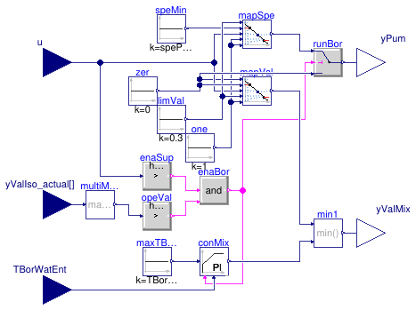
This block implements the control logic for the borefield system.
The main control signal u is yielded by the hot side
or cold side controller, see for instance
Buildings.Experimental.DHC.EnergyTransferStations.Combined.Controls.SideHot.
The system is enabled when
- the main control signal is greater than zero,
- the return position of at least one isolation valve is greater than 90%.
When the system is enabled,
- the input signal is mapped to modulate in sequence the mixing valve (from full bypass to closed bypass for a control signal varying between 0% and 30%) and the pump speed (from the minimum to the maximum value for a control signal varying between 30% and 100%),
- a PI loop tracks the maximum inlet temperature, the minimum between this loop output and the previously mapped signal being used to modulate the valve.
Note that the first control signal for the valve is needed to stabilize the control of the system when the mass flow rate required to meet the heat or cold rejection demand is below the flow rate corresponding to the minimum pump speed.
Extends from Modelica.Blocks.Icons.Block (Basic graphical layout of input/output block).
Parameters
| Type | Name | Default | Description |
|---|---|---|---|
| Temperature | TBorWatEntMax | Maximum value of borefield water entering temperature [K] | |
| Real | spePumBorMin | 0.1 | Borefield pump minimum speed [1] |
Connectors
| Type | Name | Description |
|---|---|---|
| input RealInput | yValIso_actual[2] | Isolation valves return position (fractional) |
| input RealInput | u | Control signal from supervisory |
| output RealOutput | yPum | Control signal for borefield pump [kg/s] |
| output RealOutput | yValMix | Control signal for borefield mixing valve [1] |
| input RealInput | TBorWatEnt | Borefield water entering temperature [K] |
Modelica definition
 Buildings.Experimental.DHC.EnergyTransferStations.Combined.Controls.Chiller
Chiller controller
Information
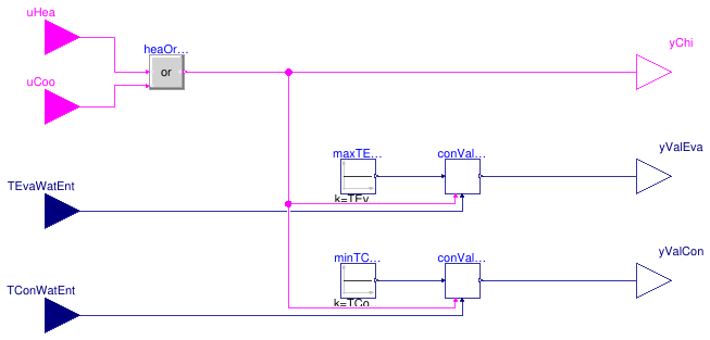
This is a controller for the chiller system, which includes the dedicated condenser and evaporator pumps.
The system is enabled if any of the input control signals uHea
or uCoo is true.
When enabled,
- the condenser and evaporator pumps are operated at constant speed,
- the condenser (resp. evaporator) mixing valve is modulated with a PI loop controlling the minimum (resp. maximum) inlet temperature.
Extends from Modelica.Blocks.Icons.Block (Basic graphical layout of input/output block).
Parameters
| Type | Name | Default | Description |
|---|---|---|---|
| Temperature | TConWatEntMin | Minimum value of condenser water entering temperature [K] | |
| Temperature | TEvaWatEntMax | Maximum value of evaporator water entering temperature [K] |
Connectors
| Type | Name | Description |
|---|---|---|
| input BooleanInput | uCoo | Cooling enable signal |
| input BooleanInput | uHea | Heating enable signal |
| input RealInput | TConWatEnt | Condenser water entering temperature [K] |
| input RealInput | TEvaWatEnt | Evaporator water entering temperature [K] |
| output RealOutput | yValCon | Condenser mixing valve control signal |
| output RealOutput | yValEva | Evaporator mixing valve control signal |
| output BooleanOutput | yChi | Chiller enable signal |
Modelica definition
 Buildings.Experimental.DHC.EnergyTransferStations.Combined.Controls.HeatExchanger
District heat exchanger controller
Information
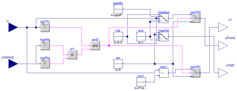
This block implements the control logic for the district heat exchanger, which realizes the interface between the building system and the district system.
The input signal u is yielded by the supervisory controller, see
Buildings.Experimental.DHC.EnergyTransferStations.Combined.Controls.Supervisory.
The primary and secondary circuits are enabled to operate if this input signal
is greater than zero and the return position of at least one isolation valve
is greater than 90%.
When enabled,
-
the secondary circuit is controlled based on the input signal
u, which is mapped to modulate in sequence the mixing valve (from full bypass to closed bypass for a control signal varying between 0% and 30%) and the pump speed (from the minimum to the maximum value for a control signal varying between 30% and 100%), -
the primary pump speed (or valve opening) is directly modulated with
the input signal
u.
Note that the valve on the secondary side is needed to stabilize the control of the system when the secondary mass flow rate required to meet the heat or cold rejection demand is below the flow rate corresponding to the minimum pump speed.
Extends from Modelica.Blocks.Icons.Block (Basic graphical layout of input/output block).
Parameters
| Type | Name | Default | Description |
|---|---|---|---|
| ConnectionConfiguration | conCon | District connection configuration | |
| Real | spePum1Min | 0.1 | Heat exchanger primary pump minimum speed (fractional) [1] |
| Real | spePum2Min | 0.1 | Heat exchanger secondary pump minimum speed (fractional) [1] |
Connectors
| Type | Name | Description |
|---|---|---|
| input RealInput | yValIso[2] | Isolation valves return position (index 1 for condenser) |
| output RealOutput | y1 | District heat exchanger primary control signal [1] |
| output RealOutput | yPum2 | District heat exchanger secondary pump control signal [1] |
| output RealOutput | yVal2 | District heat exchanger secondary valve control signal [1] |
| input RealInput | u | Control signal for secondary side (from supervisory) |
Modelica definition
 Buildings.Experimental.DHC.EnergyTransferStations.Combined.Controls.PIDWithEnable
PID controller with enable signal
Information
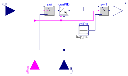
This is an update of Buildings.Controls.OBC.CDL.Reals.PIDWithReset with an additional Boolean input representing an enable signal.
-
When enabled, the controller output is identical to
Buildings.Controls.OBC.CDL.Reals.PIDWithReset
(and the controller integral term is reset to
yMinat enabling time). - When disabled, the controller output is zero (and the set point is replaced by the measurement signal to avoid any time integration of the control error).
Extends from Modelica.Blocks.Icons.Block (Basic graphical layout of input/output block).
Parameters
| Type | Name | Default | Description |
|---|---|---|---|
| SimpleController | controllerType | Buildings.Controls.OBC.CDL.T... | Type of controller |
| Real | k | 1 | Gain of controller |
| Time | Ti | 0.5 | Time constant of integrator block [s] |
| Time | Td | 0.1 | Time constant of derivative block [s] |
| Real | r | 1 | Typical range of control error, used for scaling the control error |
| Real | yMin | 0 | Lower limit of output |
| Real | yMax | 1 | Upper limit of output |
| Boolean | reverseActing | true | Set to true for reverse acting, or false for direct acting control action |
| Real | y_reset | yMin | Value to which the controller output is reset if the boolean trigger has a rising edge |
| Real | y_neutral | y_reset | Value to which the controller output is reset when the controller is disabled |
Connectors
| Type | Name | Description |
|---|---|---|
| input RealInput | u_s | Connector of setpoint input signal |
| input RealInput | u_m | Connector of measurement input signal |
| output RealOutput | y | Connector of actuator output signal |
| input BooleanInput | uEna | Enable signal |
Modelica definition
 Buildings.Experimental.DHC.EnergyTransferStations.Combined.Controls.PredictLeavingTemperature
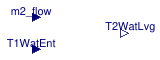
Block that predicts heat exchanger leaving water temperature
Information
This block computes the predicted heat exchanger leaving water temperature as used in Buildings.Experimental.DHC.EnergyTransferStations.Combined.Controls.WatersideEconomizer.
The predicted heat exchanger approach is computed as
dTApp = dTApp_nominal * m2_flow / m2_flow_nominal.
Which gives the predicted heat exchanger leaving water temperature as
T2WatLvg = T1WatEnt + dTApp.
Extends from Modelica.Blocks.Icons.Block (Basic graphical layout of input/output block).
Parameters
| Type | Name | Default | Description |
|---|---|---|---|
| Nominal condition | |||
| TemperatureDifference | dTApp_nominal | Heat exchanger approach [K] | |
| MassFlowRate | m2_flow_nominal | Heat exchanger secondary mass flow rate [kg/s] | |
Connectors
| Type | Name | Description |
|---|---|---|
| input RealInput | T1WatEnt | Heat exchanger primary water entering temperature [K] |
| output RealOutput | T2WatLvg | Heat exchanger secondary water leaving temperature [K] |
| input RealInput | m2_flow | Heat exchanger secondary mass flow rate [kg/s] |
Modelica definition
 Buildings.Experimental.DHC.EnergyTransferStations.Combined.Controls.PrimaryVariableFlow
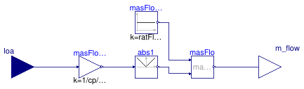
Ideal control of condenser or evaporator variable flow rate
Information
This block implements an ideal control of the evaporator (or condenser) water
mass flow rate.
The control intent aims to maintain a constant water temperature difference
dT_nominal across the heat exchanger, within the limit of a
minimum mass flow rate ratio ratFloMin.
For computational performance and to avoid the use of a PI controller,
the required mass flow rate is computed based on a signal representative of
the load.
Extends from Modelica.Blocks.Icons.Block (Basic graphical layout of input/output block).
Parameters
| Type | Name | Default | Description |
|---|---|---|---|
| HeatFlowRate | Q_flow_nominal | Heat flow rate at nominal conditions (>0 for condenser) [W] | |
| TemperatureDifference | dT_nominal | DeltaT at nominal conditions (>0 for condenser) [K] | |
| Real | ratFloMin | 0.3 | Minimum mass flow rate (ratio to nominal) [1] |
Connectors
| Type | Name | Description |
|---|---|---|
| input RealInput | loa | Signal approximating the load on condenser or evaporator [W] |
| output RealOutput | m_flow | Mass flow rate [kg/s] |
Modelica definition
 Buildings.Experimental.DHC.EnergyTransferStations.Combined.Controls.Reset
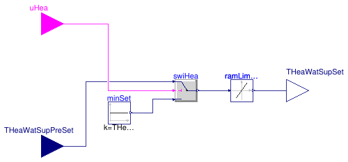
Supervisory supply temperature reset
Information
This block implements the supervisory reset of the heating water
supply temperature.
The heating water supply temperature is reset down whenever the
heating demand signal yielded by the building automation system
is false.
This enables operating the chiller at a reduced lift whenever
there is no requirement on the water temperature supplied to the
building system.
Note that the chilled water supply temperature is not reset for the sake of simplicity. It would indeed require a more involved algorithm preventing the reset in case it limits the cold rejection capacity considering the actual district water temperature.
Extends from Modelica.Blocks.Icons.Block (Basic graphical layout of input/output block).
Parameters
| Type | Name | Default | Description |
|---|---|---|---|
| Temperature | THeaWatSupSetMin | Minimum value of heating water supply temperature set point [K] |
Connectors
| Type | Name | Description |
|---|---|---|
| input BooleanInput | uHea | Heating enable signal |
| input RealInput | THeaWatSupPreSet | Heating water supply temperature set point [K] |
| output RealOutput | THeaWatSupSet | Heating water supply temperature set point after reset [K] |
Modelica definition
 Buildings.Experimental.DHC.EnergyTransferStations.Combined.Controls.SideCold
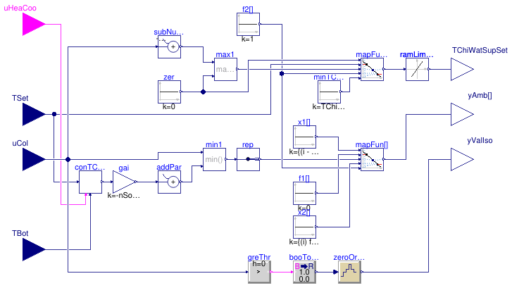
Control block for cold side
Information
This block serves as the controller for the cold side of the ETS in Buildings.Experimental.DHC.EnergyTransferStations.Combined.Controls.Supervisory. It computes the following control signals.
-
Control signals for ambient sources
yAmb(array)
The cold rejection control signal yielded by the hot side controller is processed as follows.-
A controller is used to track the chilled water
supply temperature (CHWST) set point.
This controller is enabled when cooling is enabled.
It yields a control signal value between
0andnSouAmb. -
The systems serving as ambient sources are then controlled in sequence
by mapping the minimum between the CHWST control loop output and the
part of the cold rejection signal between
0andnSouAmbto anSouAmb-array of signals between0and1.
-
A controller is used to track the chilled water
supply temperature (CHWST) set point.
This controller is enabled when cooling is enabled.
It yields a control signal value between
-
Chilled water supply temperature set point
TChiWatSupSet
The remaining part of the cold rejection signal betweennSouAmbandnSouAmb+1is used to reset the CHWST set point between a maximum value provided as an input variable, and a minimum value provided as a parameter. -
Control signal for the evaporator loop isolation valve
yIsoAmb
The valve is commanded to be fully open whenever the cold rejection control signal is greater than zero. The command signal is held for 60s to avoid short cycling.
Extends from Modelica.Blocks.Icons.Block (Basic graphical layout of input/output block).
Parameters
| Type | Name | Default | Description |
|---|---|---|---|
| Integer | nSouAmb | 1 | Number of ambient sources to control |
| Temperature | TChiWatSupSetMin | Minimum value of chilled water supply temperature set point [K] | |
| SimpleController | controllerType | Buildings.Controls.OBC.CDL.T... | Type of controller |
| Real | k | 0.1 | Gain of controller |
| Time | Ti | 120 | Time constant of integrator block [s] |
Connectors
| Type | Name | Description |
|---|---|---|
| input RealInput | uCol | Cold rejection control signal |
| output RealOutput | TChiWatSupSet | Chilled water supply temperature set point [K] |
| input BooleanInput | uHeaCoo | Enable signal for heating or cooling |
| input RealInput | TSet | Supply temperature set point (heating or chilled water) [K] |
| input RealInput | TBot | Temperature at bottom of tank [K] |
| output RealOutput | yAmb[nSouAmb] | Control signal for ambient sources [1] |
| output RealOutput | yValIso | Ambient loop isolation valve control signal [1] |
Modelica definition
 Buildings.Experimental.DHC.EnergyTransferStations.Combined.Controls.SideHot
Control block for hot side
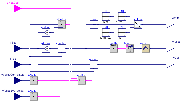
Information
This block serves as the controller for the hot side of the ETS in Buildings.Experimental.DHC.EnergyTransferStations.Combined.Controls.Supervisory. It computes the following control signals.
-
Control signals for ambient sources
yAmb(array)
The controller for heat rejection is enabled when the return position of the evaporator loop isolation valve is close to zero. When enabled, it maintains the temperature at the top of the heating water tank at the heating water supply temperature set point plus a dead banddTDea. The controller yields a control signal value between0andnSouAmb. The systems serving as ambient sources are then controlled in sequence by mapping the controller output to anSouAmb-array of signals between0and1. -
Control signal for cold rejection
yCol
The controller for cold rejection is enabled if- the return position of the condenser loop isolation valve is close to zero, and
- heating is enabled, and
-
the temperature at the top of the heating water tank is below a safety
limit equal to the heating water supply temperature set point plus the
parameter
dTLoc. This last condition limits the temperature overshoot after the warmup periods, without having to finely tune the heat and cold rejection controller parameters to guard against the disturbing effect of a varying district water temperature.
0andnSouAmb+1which is connected to Buildings.Experimental.DHC.EnergyTransferStations.Combined.Controls.SideCold where it is used to control in sequence the systems serving as ambient sources and ultimately to reset down the chilled water supply temperature. -
Control signal for the condenser loop isolation valve
yIsoAmb
The valve is commanded to be fully open whenever the controller for heat rejection yields an output signal greater than zero. The command signal is held for 60s to avoid short cycling.
Extends from Modelica.Blocks.Icons.Block (Basic graphical layout of input/output block).
Parameters
| Type | Name | Default | Description |
|---|---|---|---|
| Integer | nSouAmb | 1 | Number of ambient sources to control |
| TemperatureDifference | dTDea | 1 | Temperature difference band between set point tracking and heat rejection (absolute value) [K] |
| TemperatureDifference | dTLoc | dTDea + 2 | Temperature difference between set point tracking and cold rejection lockout (absolute value) [K] |
| SimpleController | controllerType | Buildings.Controls.OBC.CDL.T... | Type of controller |
| Real | k | 0.1 | Gain of controller |
| Time | Ti | 120 | Time constant of integrator block [s] |
Connectors
| Type | Name | Description |
|---|---|---|
| output RealOutput | yCol | Control signal for cold side [1] |
| input BooleanInput | uHeaCoo | Enable signal for heating or cooling |
| input RealInput | TSet | Supply temperature set point (heating or chilled water) [K] |
| input RealInput | TTop | Temperature at top of tank [K] |
| output RealOutput | yAmb[nSouAmb] | Control signal for ambient sources [1] |
| output RealOutput | yValIso | Ambient loop isolation valve control signal [1] |
| input RealInput | yValIsoCon_actual | Return position of condenser to ambient loop isolation valve [1] |
| input RealInput | yValIsoEva_actual | Return position of evaporator to ambient loop isolation valve [1] |
Modelica definition
 Buildings.Experimental.DHC.EnergyTransferStations.Combined.Controls.Supervisory
Supervisory controller
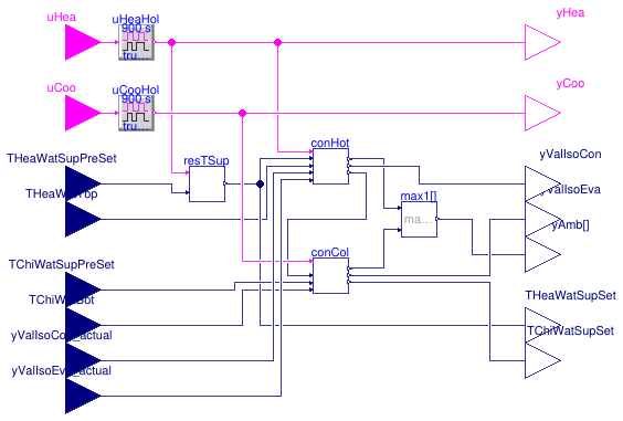
Information
This block implements the supervisory control functions of the ETS model Buildings.Experimental.DHC.EnergyTransferStations.Combined.ChillerBorefield.
-
Heating (resp. cooling) is enabled based on the input signal
uHea(resp.uCoo) which is held for 15', meaning that, when enabled, the mode remains active for at least 15 minutes and, when disabled, the mode cannot be enabled again for at least 15 minutes. The heating and cooling enable signals should be computed externally based on a schedule (to lock out the system during off-hours), ideally in conjunction with the number of requests yielded by the terminal unit controllers, or any other signal representative of the load. Indeed, the heating water supply set point is allowed to be reset down only when heating is disabled, in which case the system performance is improved due to a lower chiller lift. - The controller resets the heating water supply temperature based on the logic described in Buildings.Experimental.DHC.EnergyTransferStations.Combined.Controls.Reset. Note that this resetting logic is meant to operate the chiller at low lift. The chilled water supply temperature may be also reset down by Buildings.Experimental.DHC.EnergyTransferStations.Combined.Controls.SideCold to maintain the heating water supply temperature set point. This second resetting logic is required for the heating function of the unit, but it has a negative impact on the lift.
-
Eventually the systems serving as ambient sources are controlled based on the
maximum of the control signals
yAmbyielded by Buildings.Experimental.DHC.EnergyTransferStations.Combined.Controls.SideHot and Buildings.Experimental.DHC.EnergyTransferStations.Combined.Controls.SideCold.
Extends from Buildings.Experimental.DHC.EnergyTransferStations.Combined.Controls.BaseClasses.PartialSupervisory (Partial model for supervisory controller).
Parameters
| Type | Name | Default | Description |
|---|---|---|---|
| Integer | nSouAmb | Number of ambient sources to control | |
| SimpleController | controllerType | Buildings.Controls.OBC.CDL.T... | Type of controller |
| Real | kHot | 0.05 | Gain of controller on hot side |
| Real | kCol | 0.1 | Gain of controller on cold side |
| Time | TiHot | 300 | Time constant of integrator block on hot side [s] |
| Time | TiCol | 120 | Time constant of integrator block on cold side [s] |
| Temperature | THeaWatSupSetMin | Minimum value of heating water supply temperature set point [K] | |
| Temperature | TChiWatSupSetMin | Minimum value of chilled water supply temperature set point [K] |
Connectors
| Type | Name | Description |
|---|---|---|
| input BooleanInput | uHea | Heating enable signal |
| input BooleanInput | uCoo | Cooling enable signal |
| input RealInput | TChiWatSupPreSet | Chilled water supply temperature set point [K] |
| input RealInput | TChiWatBot | Chilled water temperature at tank bottom [K] |
| input RealInput | THeaWatTop | Heating water temperature at tank top [K] |
| input RealInput | THeaWatSupPreSet | Heating water supply temperature set point [K] |
| output RealOutput | THeaWatSupSet | Heating water supply temperature set point after reset [K] |
| output RealOutput | TChiWatSupSet | Chilled water supply temperature set point after reset [K] |
| output RealOutput | yValIsoEva | Evaporator to ambient loop isolation valve control signal [1] |
| output RealOutput | yValIsoCon | Condenser to ambient loop isolation valve control signal [1] |
| output RealOutput | yAmb[nSouAmb] | Control output for ambient sources [1] |
| output BooleanOutput | yHea | Tank in heating demand |
| output BooleanOutput | yCoo | Tank in cooling demand |
| input RealInput | yValIsoCon_actual | Return position of condenser to ambient loop isolation valve [1] |
| input RealInput | yValIsoEva_actual | Return position of evaporator to ambient loop isolation valve [1] |
Modelica definition
 Buildings.Experimental.DHC.EnergyTransferStations.Combined.Controls.SwitchBox
Controller for flow switch box
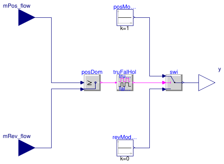
Information
This block implements a control logic preventing flow reversal in the
service line, for instance with the hydronic configuration of
Buildings.Experimental.DHC.EnergyTransferStations.Combined.HeatPumpHeatExchanger.
The block requires two input signals representing the mass flow rate contributing
to a positive flow direction mPos_flow and the mass flow contributing
to a reverse flow direction mRev_flow.
The output signal y switches to maintain mPos_flow ≥ mRev_flow
with a temporization avoiding short cycling.
Due to the temporization, the mass flow rate may transiently change direction as
illustrated in
Buildings.Experimental.DHC.EnergyTransferStations.Combined.Subsystems.Validation.SwitchBox.
Extends from Modelica.Blocks.Icons.Block (Basic graphical layout of input/output block).
Parameters
| Type | Name | Default | Description |
|---|---|---|---|
| Real | trueHoldDuration | true hold duration [s] | |
| Real | falseHoldDuration | trueHoldDuration | false hold duration [s] |
Connectors
| Type | Name | Description |
|---|---|---|
| input RealInput | mPos_flow | Service water mass flow rate in positive direction [kg/s] |
| input RealInput | mRev_flow | Service water mass flow rate in reverse direction [kg/s] |
| output RealOutput | y | Control output signal [1] |
Modelica definition
 Buildings.Experimental.DHC.EnergyTransferStations.Combined.Controls.WatersideEconomizer
Waterside economizer controller
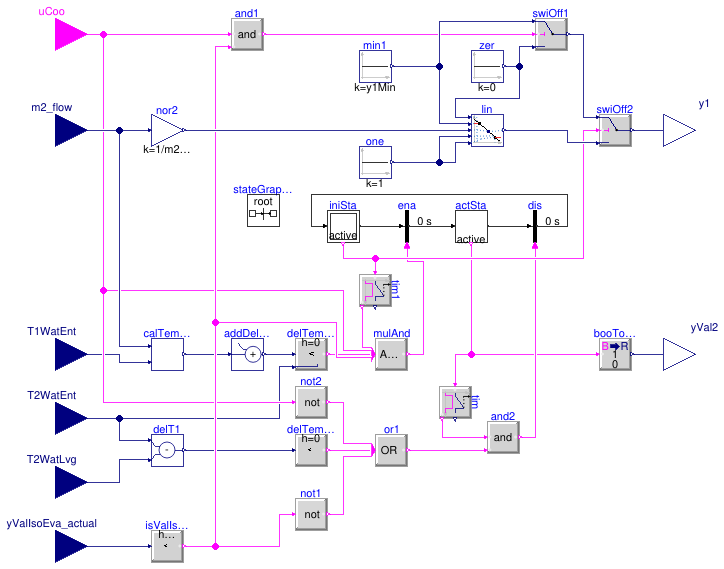
Information
This block implements the control logic for the waterside economizer.
The system is enabled if
- it has been disabled for more than 20 minutes, and
-
the "cooling enabled" input signal is
true, and - the evaporator isolation valve is closed (i.e., the system is not in cold rejection mode), and
-
the predicted leaving water temperature is lower than the entering water
temperature minus
dTEna.
The system is disabled if
- it has been enabled for more than 20 minutes, and
-
the "cooling enabled" input signal is
false, or - the evaporator isolation valve is open, or
-
the leaving water temperature is higher than the entering water
temperature minus
dTDis.
When the system is enabled
- the primary side is controlled so that the primary flow rate varies linearly with the secondary flow rate,
- the bypass valve on the secondary side is fully closed.
When the system is disabled
-
if the "cooling enabled" input signal is
trueand the evaporator isolation valve is closed, the primary pump (resp. valve) is operated at its minimum speed (resp. opening), otherwise it is switched off (resp. fully closed): this is needed to yield a representative measurement of the service water entering temperature, - the bypass valve on the secondary side is fully open.
Extends from Modelica.Blocks.Icons.Block (Basic graphical layout of input/output block).
Parameters
| Type | Name | Default | Description |
|---|---|---|---|
| Nominal condition | |||
| MassFlowRate | m2_flow_nominal | Heat exchanger secondary mass flow rate [kg/s] | |
| Temperature | T_a1_nominal | Nominal water inlet temperature on district side [K] | |
| Temperature | T_b2_nominal | Nominal water outlet temperature on building side [K] | |
| Controls | |||
| Real | y1Min | 0.05 | Minimum pump flow rate or valve opening for temperature measurement (fractional) [1] |
| TemperatureDifference | dTEna | 1 | Minimum delta-T above predicted heat exchanger leaving water temperature to enable WSE [K] |
| TemperatureDifference | dTDis | 0.5 | Minimum delta-T across heat exchanger before disabling WSE [K] |
Connectors
| Type | Name | Description |
|---|---|---|
| input RealInput | T1WatEnt | Heat exchanger primary water entering temperature [K] |
| input RealInput | m2_flow | Heat exchanger secondary mass flow rate [kg/s] |
| input RealInput | T2WatLvg | Heat exchanger secondary water leaving temperature [K] |
| input RealInput | T2WatEnt | Heat exchanger secondary water entering temperature [K] |
| output RealOutput | y1 | Primary control signal (pump or valve) [1] |
| output RealOutput | yVal2 | Secondary valve control signal [1] |
| input BooleanInput | uCoo | Cooling enable signal |
| input RealInput | yValIsoEva_actual | Return position of evaporator to ambient loop isolation valve [1] |